- Apparatus of installations with fluidized layer of pulverized catalyst

Содержание
- 2. Plan Introduction; Main features of the process; Conclusion;
- 3. Catalytic cracking units with a fluidized bed of a pulverized or microspherical catalyst operate on a
- 4. The advantages of this type of cracking compared to cracking, which uses a ball catalyst, are:
- 5. The disadvantage of cracking in a fluidized bed is that due to the intensive mixing of
- 6. There are four main schemes of the reactor unit: The scheme with a double rise of
- 7. Scheme with the location of the reactor and regenerator on the same level. The catalyst is
- 8. Reactors of modern cracking plants with a fluidized bed of the catalyst are vertical cylindrical apparatus
- 9. 1-raw material and catalyst distribution zone; 2-reaction zone; 3-settling zone; 4-cyclones; 5-Stripping zone; I-raw material and
- 11. Скачать презентацию
Plan
Introduction;
Main features of the process;
Conclusion;
Plan
Introduction;
Main features of the process;
Conclusion;
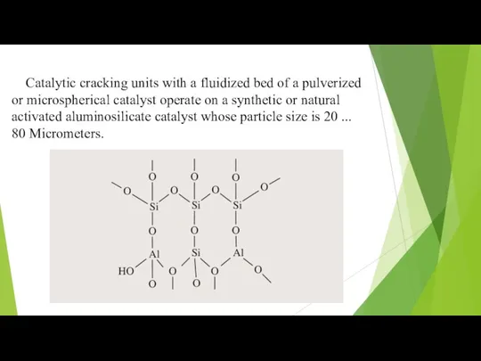
Catalytic cracking units with a fluidized bed of a pulverized or
Catalytic cracking units with a fluidized bed of a pulverized or
The advantages of this type of cracking compared to cracking, which
The advantages of this type of cracking compared to cracking, which
The disadvantage of cracking in a fluidized bed is that due
The disadvantage of cracking in a fluidized bed is that due
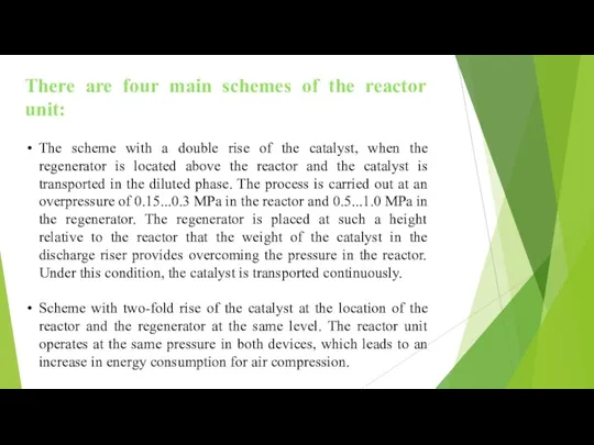
There are four main schemes of the reactor unit:
The scheme with
There are four main schemes of the reactor unit:
The scheme with
Scheme with the location of the reactor and regenerator on the
Scheme with the location of the reactor and regenerator on the
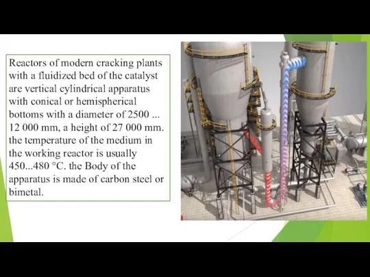
Reactors of modern cracking plants with a fluidized bed of the
Reactors of modern cracking plants with a fluidized bed of the
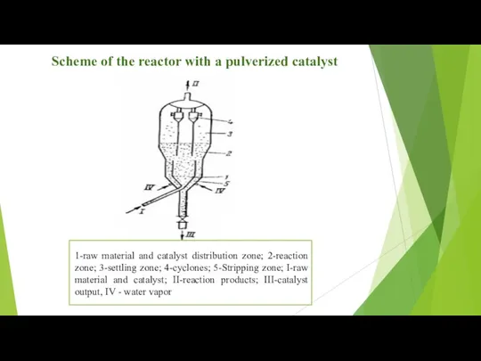
1-raw material and catalyst distribution zone; 2-reaction zone; 3-settling zone; 4-cyclones;
1-raw material and catalyst distribution zone; 2-reaction zone; 3-settling zone; 4-cyclones;
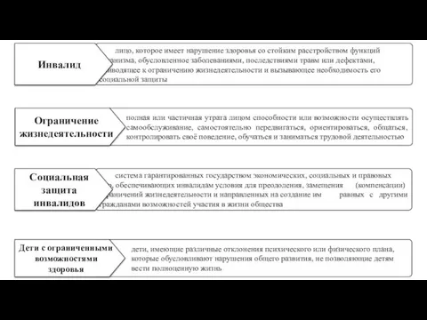 Социальная работа с детьми, имеющими ограниченные возможности здоровья
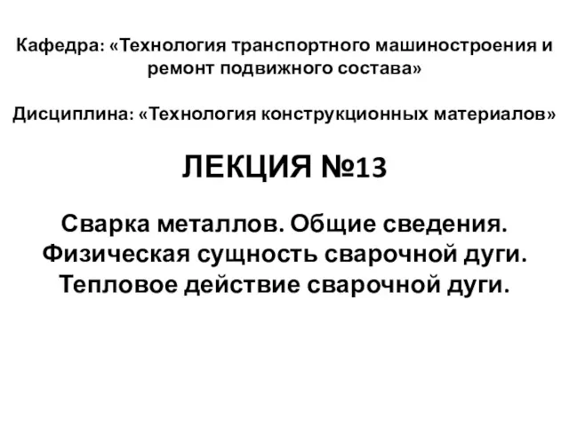 Сварка металлов. Общие сведения. Физическая сущность сварочной дуги. Тепловое действие сварочной дуги
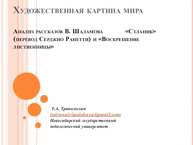 Художественная картина мира. Анализ рассказов В. Шаламова Стланик и Воскрешение лиственницы
 Les Types de Phrases
 Презенация Социально-личностное развитие дошкольника с учётом гендерных особенностей
 Обеспечение химической защиты
 Внеклассное мероприятие Знайте правила движения как таблицу умножения!
 Отрезок. Длина отрезка. Прямая. Луч. 5 класс
 Землеройно-транспортные машины. Классификация, устройство, назначение
 Споживання кормів та його регуляція. Лекція 7
 о-е после шип в наречиях
 Оператор комп’ютерного набору
 Классный час Берегите глаза
 Результаты метапредметной диагностической работы
 Особенности педагогической деятельности с обучающимися с интеллектуальными нарушениями
 Тағамды сақтау жолы консервілеу
 ДопускКпеддеят.ОткрУрок03.12.2020
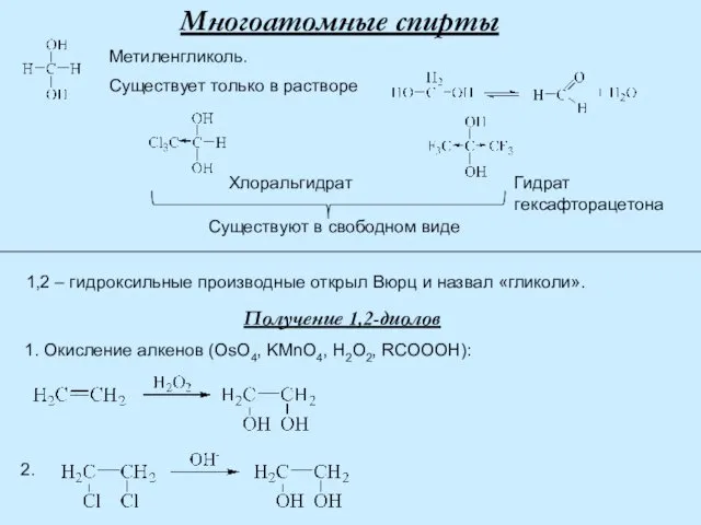 Многоатомные спирты
 GP2 BCM SVC bulletin Document 4.01.00
 Coffee Zavod. Доходная кофейня самообслуживания
 Путешествие в Иерусалим
 Автоматизация звука Ш в словах
 Акты действия (бездействия) ОГВ и ОМС, направленные на ограничение конкуренции
 Склад та властивості нафти
 Презентация к празднику Победой кончилась война. Диск
 phppb0sz2_Madame-Tussauds
 Окислительно-восстановительные реакции
 Биоритмология