- Ball Charge Design and Management

Содержание
- 2. Grinding is a transfer of energy… 30mm ? 3mm 2 kWh/t 3mm ? 300µm 6 kWh/t
- 3. … from a mill to particles… (mill motors = 85% of the power absorbed in the
- 4. Assumptions: lever b is proportional to Di lever b is independent from mill speed c =
- 5. … with a poor efficiency (95% lost in heat) 50mm ? ~ 0,5mm Crushing is more
- 6. Matching Ball Sizes…
- 7. … without forgetting the effect of the liners
- 8. Porosity Average ball weight total charge weight / total number of balls kg/ball Specific surface area
- 9. Ball movement according filling degree / critical speed Ball charge - % of mill volume Area
- 10. Ball volume loading Minimum Grinding Energy (kWh/t) VL = approx. 25%
- 11. A = Free surface S = Surface area of charge The required surface area [S] can
- 12. Calculation of filling degree
- 13. 27 - 35% 65 - 73% Length to diameter ratio (for OPC): 1st. Chamber 30 –
- 14. Ball Charge Fundamentals In a ball mill, the balls grind the material Match the charge to
- 15. How to design a ball charge and manage it? Calculation of a theoretical ball charge (always
- 16. Theoretical ball charge Parameters Product: type, composition, fineness, throughput… the ball charge design must produce the
- 17. Design methodology Numerous attempts to make the process more scientific and rigorous Slegten, Polysius Models Lafarge
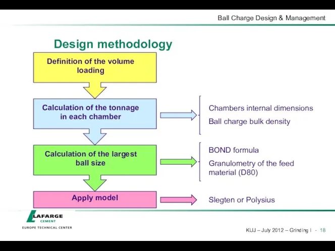
- 18. Design methodology
- 19. Ball volume loading The recommended volume loading for minimum kWh/t is based on an acceptable compromise
- 20. Biggest ball where, Ømax = biggest ball diameter, mm D20 = sieve dimension where 20% is
- 21. Ball charge design - C1 Emphasis on crushing and less on grinding Typical top size 80
- 22. Ball charge design - C2 Emphasis on attrition grinding Cement grinding wants maximum fines generation (Blaine)
- 23. Effective length curves Convert the % weight to equivalent % length Plot effective mill length vs.
- 24. Why use a curve? Only so much grinding can be done over a given length of
- 25. Polysius design Use exponential curve Start with 90mm top size Result depends on compartment length @
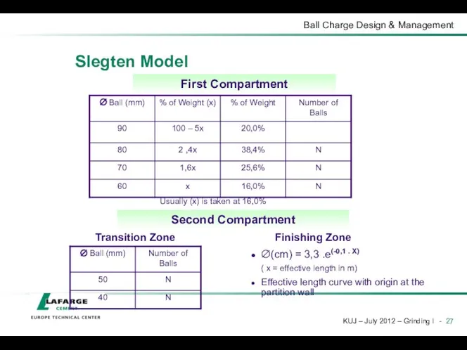
- 26. Slegten Model Divides the mill into 3 parts Preparation in the 1st Compartment Same quantity of
- 27. Slegten Model First Compartment Usually (x) is taken at 16,0% Second Compartment Transition Zone Finishing Zone
- 28. Slegten model example calculation Material characteristics Clinker D80 = 15 mm Wi = 13,49 kWh/t ρ
- 29. Slegten model example calculation Closed circuit cement mill L/D = 3 Du = 3,65 m Lu
- 30. Excercise Calculate biggest ball Remember Propose a ball charge (Slegten)
- 31. Ball charge optimization (existing mill) Calculate theoretical ball charge as a reference Perform a mill audit
- 32. Ball charge management Having a well-designed ball charge is one thing… … but you need to
- 33. Top-ups Follow-up at least every month Check mill power consumption (same product every time) Free height
- 34. Ball charge sorting Objective Eliminate scrap, broken and undersize balls scrap = foreign metallic elements polluting
- 35. Sorting method Purge mill, take everything out of the compartment Sort, weigh and record By size
- 37. Скачать презентацию
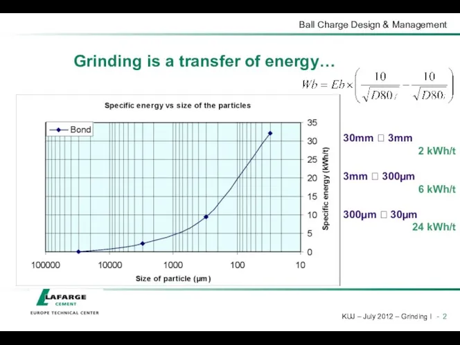
Grinding is a transfer of energy…
30mm ? 3mm
2 kWh/t
3mm ? 300µm
6
Grinding is a transfer of energy…
30mm ? 3mm
2 kWh/t
3mm ? 300µm
6
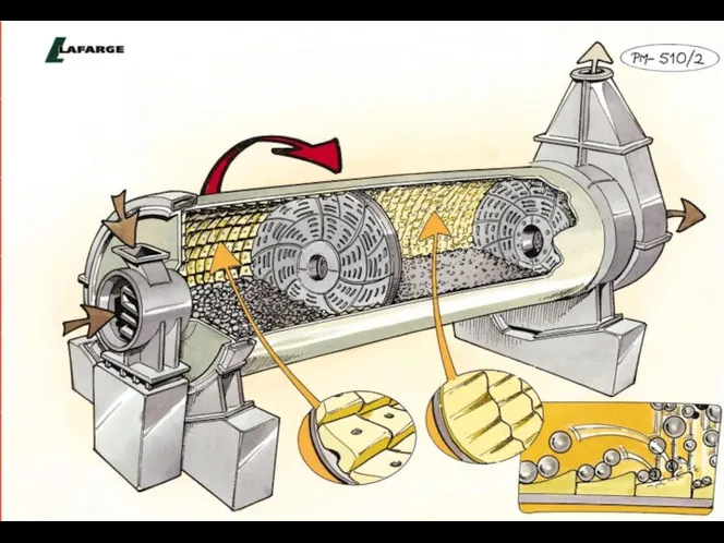
… from a mill to particles…
(mill motors = 85% of the
… from a mill to particles… (mill motors = 85% of the
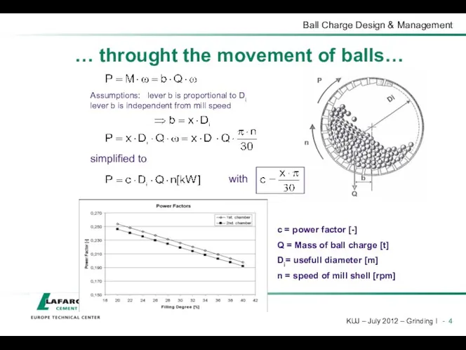
Assumptions: lever b is proportional to Di lever b is independent
Assumptions: lever b is proportional to Di lever b is independent

… with a poor efficiency (95% lost in heat)
50mm ? ~
… with a poor efficiency (95% lost in heat)
50mm ? ~
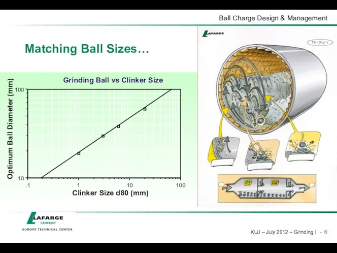
Matching Ball Sizes…
Matching Ball Sizes…
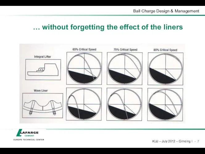
… without forgetting the effect of the liners
… without forgetting the effect of the liners

Porosity
Average ball weight
total charge weight / total number of balls
kg/ball
Specific surface
Porosity
Average ball weight
total charge weight / total number of balls
kg/ball
Specific surface
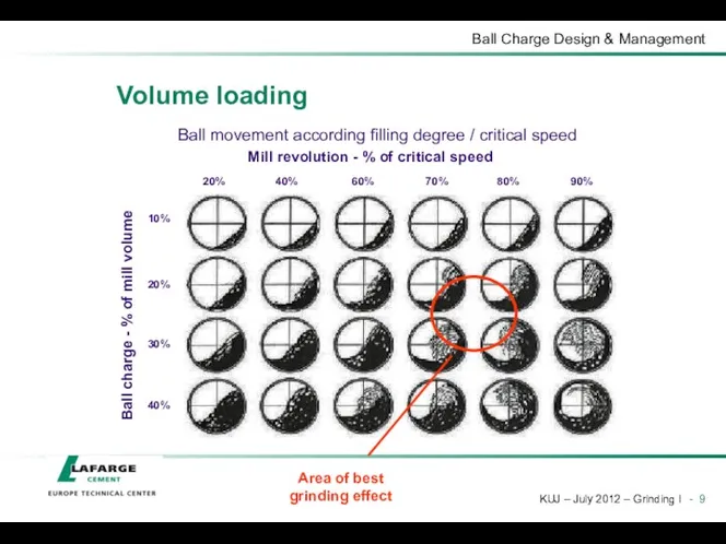
Ball movement according filling degree / critical speed
Ball charge - %
Ball movement according filling degree / critical speed
Ball charge - %
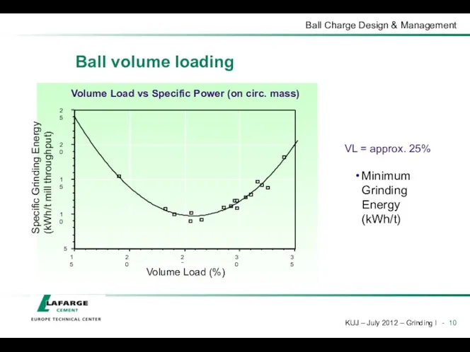
Ball volume loading
Minimum Grinding Energy (kWh/t)
VL = approx. 25%
Ball volume loading
Minimum Grinding Energy (kWh/t)
VL = approx. 25%

A = Free surface
S = Surface area of charge
The required surface
A = Free surface
S = Surface area of charge
The required surface
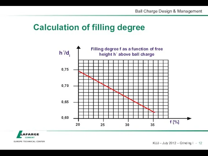
Calculation of filling degree
Calculation of filling degree
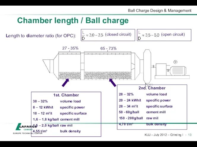
27 - 35%
65 - 73%
Length to diameter ratio (for OPC):
1st. Chamber
30
27 - 35%
65 - 73%
Length to diameter ratio (for OPC):
1st. Chamber
30
Ball Charge Fundamentals
In a ball mill, the balls grind the material
Match
Ball Charge Fundamentals
In a ball mill, the balls grind the material
Match

How to design a ball charge and manage it?
Calculation of a
How to design a ball charge and manage it?
Calculation of a

Theoretical ball charge
Parameters
Product: type, composition, fineness, throughput…
the ball charge design must
Theoretical ball charge
Parameters
Product: type, composition, fineness, throughput…
the ball charge design must
Design methodology
Numerous attempts to make the process more scientific and rigorous
Slegten,
Design methodology
Numerous attempts to make the process more scientific and rigorous
Slegten,
Design methodology
Design methodology
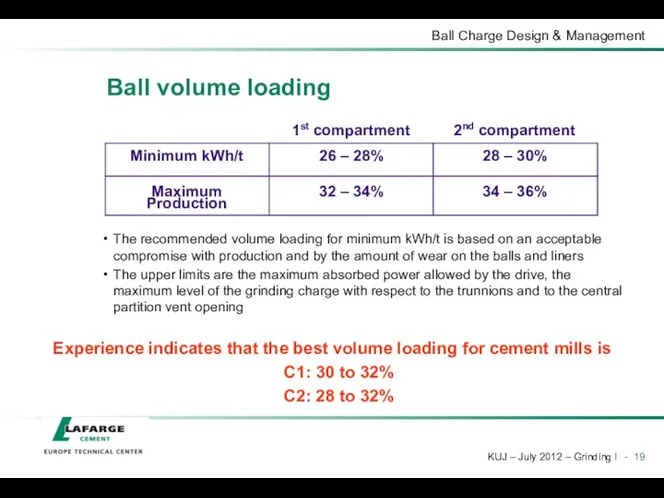
Ball volume loading
The recommended volume loading for minimum kWh/t is based
Ball volume loading
The recommended volume loading for minimum kWh/t is based
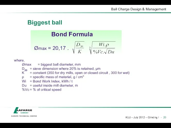
Biggest ball
where,
Ømax = biggest ball diameter, mm
D20 = sieve dimension where 20% is
Biggest ball
where,
Ømax = biggest ball diameter, mm
D20 = sieve dimension where 20% is
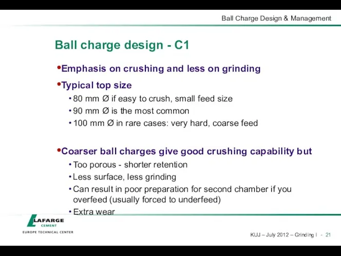
Ball charge design - C1
Emphasis on crushing and less on grinding
Typical
Ball charge design - C1
Emphasis on crushing and less on grinding
Typical
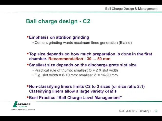
Ball charge design - C2
Emphasis on attrition grinding
Cement grinding wants maximum
Ball charge design - C2
Emphasis on attrition grinding
Cement grinding wants maximum
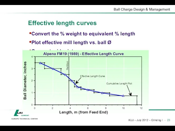
Effective length curves
Convert the % weight to equivalent % length
Plot effective
Effective length curves
Convert the % weight to equivalent % length
Plot effective
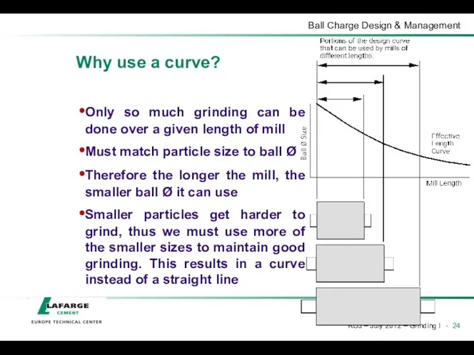
Why use a curve?
Only so much grinding can be done over
Why use a curve?
Only so much grinding can be done over
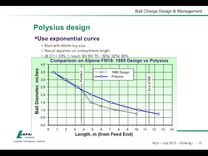
Polysius design
Use exponential curve
Start with 90mm top size
Result depends on compartment
Polysius design
Use exponential curve
Start with 90mm top size
Result depends on compartment
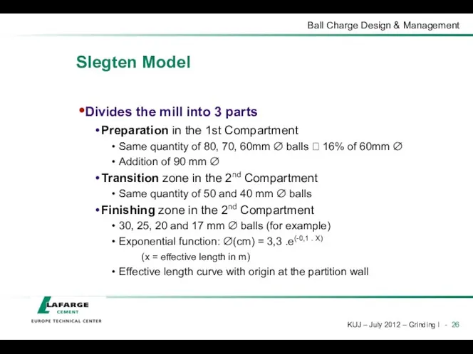
Slegten Model
Divides the mill into 3 parts
Preparation in the 1st Compartment
Slegten Model
Divides the mill into 3 parts
Preparation in the 1st Compartment
Slegten Model
First Compartment
Usually (x) is taken at 16,0%
Second Compartment
Transition Zone
Finishing Zone
∅(cm)
Slegten Model
First Compartment
Usually (x) is taken at 16,0%
Second Compartment
Transition Zone
Finishing Zone
∅(cm)
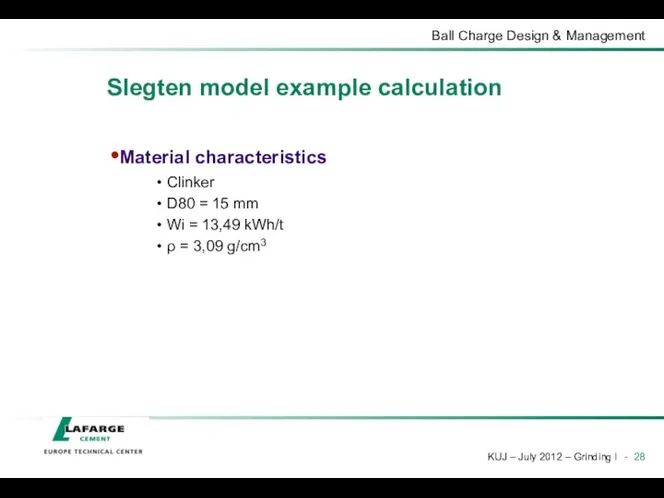
Slegten model example calculation
Material characteristics
Clinker
D80 = 15 mm
Wi = 13,49 kWh/t
ρ
Slegten model example calculation
Material characteristics
Clinker
D80 = 15 mm
Wi = 13,49 kWh/t
ρ
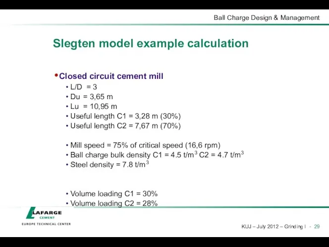
Slegten model example calculation
Closed circuit cement mill
L/D = 3
Du = 3,65 m
Lu
Slegten model example calculation
Closed circuit cement mill
L/D = 3
Du = 3,65 m
Lu
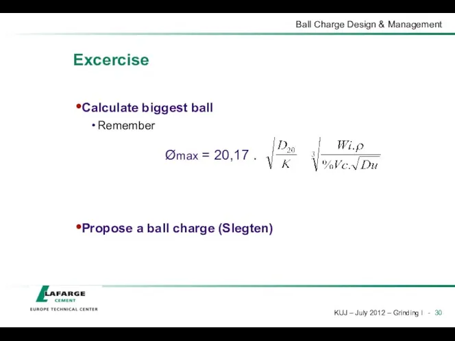
Excercise
Calculate biggest ball
Remember
Propose a ball charge (Slegten)
Excercise
Calculate biggest ball
Remember
Propose a ball charge (Slegten)

Ball charge optimization (existing mill)
Calculate theoretical ball charge as a reference
Perform
Ball charge optimization (existing mill)
Calculate theoretical ball charge as a reference
Perform
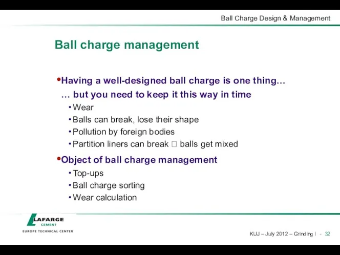
Ball charge management
Having a well-designed ball charge is one thing…
… but
Ball charge management
Having a well-designed ball charge is one thing…
… but

Top-ups
Follow-up at least every month
Check mill power consumption (same product every
Top-ups
Follow-up at least every month
Check mill power consumption (same product every
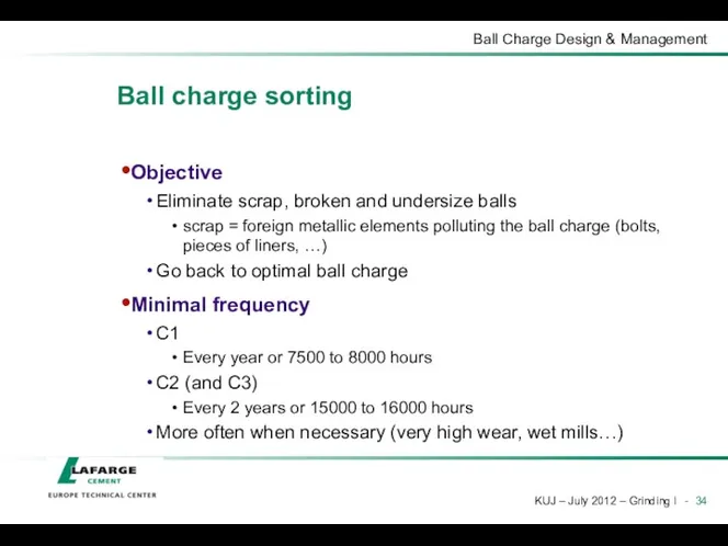
Ball charge sorting
Objective
Eliminate scrap, broken and undersize balls
scrap = foreign metallic
Ball charge sorting
Objective
Eliminate scrap, broken and undersize balls
scrap = foreign metallic
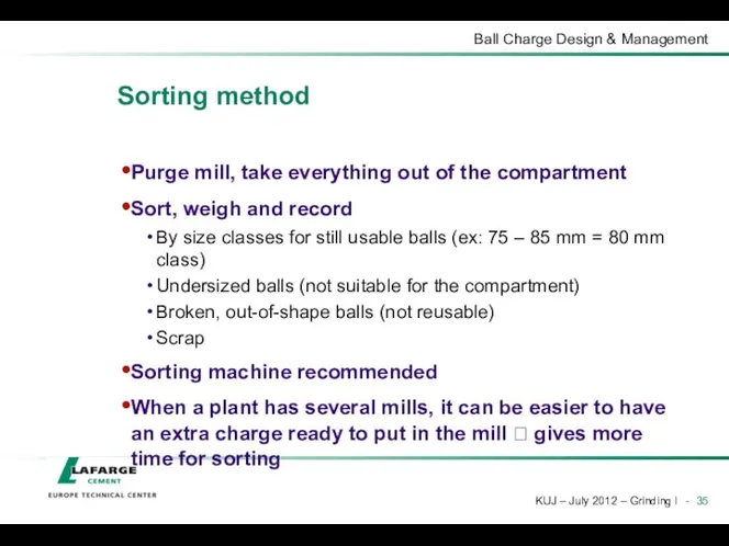
Sorting method
Purge mill, take everything out of the compartment
Sort, weigh and
Sorting method
Purge mill, take everything out of the compartment
Sort, weigh and
 Адаптированная программа дошкольного образования для детей с задержкой психического развития
 Материалы к Празднику знаний -1сентября Диск
 Внеклассное мероприятие Вежливые слова
 Своя игра (игра-соревнование)
 Мировая экономика
 Азбука безопасности. Словарик
 هوش مصنوعی
 20231026_osobennosti_organizatsii_olimpiad_po_informatike
 Презентация к практическому занятию по химии в 5 классе.
 D элементтеріне жалпы сипаттама
 Разработка системы автоматического регулирования питания барабанного котельного агрегата водой (на материалах АО ССГПО)
 Русь в правление Ивана Грозного (1533 - 1584)
 Медико-демографические проблемы населения России
 Мультибрендовая платформа FROZA. Автозапчасти и аксессуары для авто, мото, грузовой и спецтехники
 Modern construction technologies
 Новая система обращения с твердыми коммунальными отходами
 Социальная сеть Facebook
 Интеллектуальная игра Пентагон
 Загадки про грибы
 Понятие и сущность международного права. (Лекция 1)
 Подготовка деталей перед сборкой и сваркой. Сборка и сварка
 Великобритания во второй половине XX века
 презентация №Фенол
 Индекс экономической безопасности
 Балалардағы экг ерекшеліктері.Жүрек тондарының пайда болу механизмдері
 Определение надежности, безотказности, работоспособности, долговечности, ремонтопригодности
 Семья.Семейные ценности.
 Возбудитель коклюша Bordetella pertussis