- BL BOSCH 5.3 ABS. System Description of BL ABS

Содержание
- 2. ▶ System - BOSCH ABS 5.3 - 4Sensor 4Channel - BRAKE Line : X Split -
- 3. EV AV MOTOR PUMP BL ABS Specification
- 4. ▶ABS5.3 model HECU
- 5. HECU Location
- 6. ▶ABS 5.3 ▶Top view ▶Bottom view ECU connector Accumulator Damping Chamber Motor Power line HECU Appearance
- 7. ▶ Never Disassemble HECU ▶ valve seat coil assembly ABSCM Housing
- 8. ABSCM Input & Output
- 9. VALVE, MOTOR RELAY FUSE Valve/Pump motor relay fuse
- 10. Acceleration Sensor
- 11. Return Pump Hydraulic Unit FL RR FR RL Diagonal Circuit of BL ABS5.3
- 12. ▣ Normal Condition Hydraulic Unit (Modulator)
- 13. Brake pressure from the M/C directly delivers to wheel cylinders ABSCM does not operate Normal braking
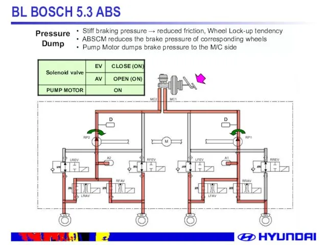
- 14. Stiff braking pressure → reduced friction, Wheel Lock-up tendency ABSCM reduces the brake pressure of corresponding
- 15. To make a proper decision of wheel rotation while pressure dump or pressure increase mode To
- 16. If a frictional force between tire and road surface increases, ABSCM increases brake pressure again Pressure
- 17. 1. EBD Modulation 2. Advantage of EBD 3. EBD Failure Matrix(Rev. 4) EBD(Electronic Brake-force Distribution)
- 18. EBD Modulation * EBD control example
- 19. EBD Curve
- 20. (load sensitive) proportioning valve may be omitted increase of rear axle contribution to brake-force Approach to
- 21. Failure Matrix of EBD Rev.4
- 22. EBD & Parking brake lamp • ECU Failure • Solenoid Valve Failure • Paring Brake •
- 23. 1. ABS & EBD Warning Lamp(Passive Type) 2. ABS External Wiring Diagram 3. ABSCM Connector 4.
- 24. ABS & EBD Warning Lamp(Passive Type)
- 25. ABS External Wiring Diagram
- 26. Wiring Diagram
- 27. ABSCM Connector
- 28. Pin Assignment
- 29. 1. DTC list 2. System failure diagnosis 3. Air Bleeding 4. Hi-Scan Pro Troubleshooting
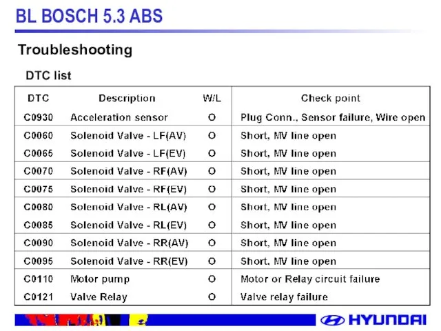
- 30. Troubleshooting DTC list
- 31. Troubleshooting DTC list
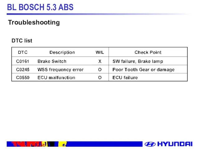
- 32. Troubleshooting DTC list
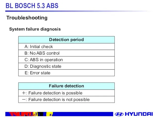
- 33. Detection period A: Initial check B: No ABS control C: ABS in operation D: Diagnostic state
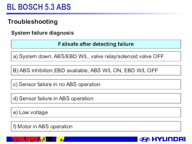
- 34. Failsafe after detecting failure a) System down, ABS/EBD W/L, valve relay/solenoid valve OFF B) ABS inhibition,EBD
- 35. ☞ 나머지 조건들은 “Failure List of Self Diagnose” 참조 Troubleshooting System failure diagnosis
- 36. 1. Same procedure as CBS air-bleeding 2. When air remains inside brake pipe - Normal air
- 38. Скачать презентацию
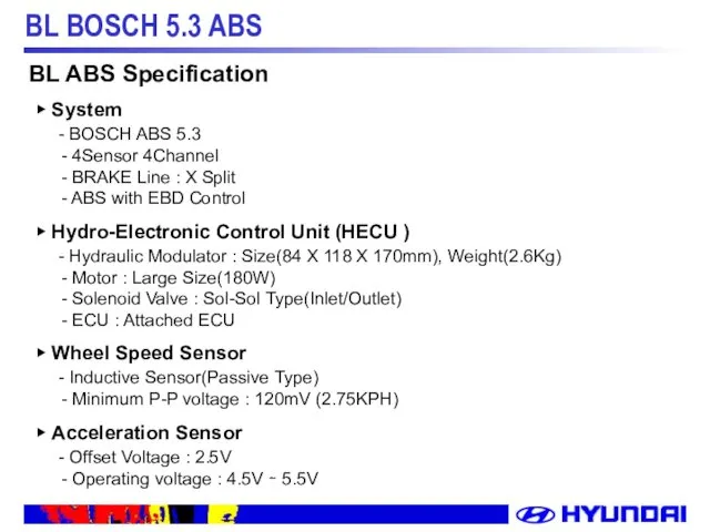
▶ System
- BOSCH ABS 5.3
- 4Sensor 4Channel
-
▶ System
- BOSCH ABS 5.3
- 4Sensor 4Channel
-
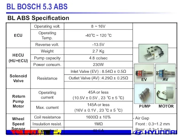
EV
AV
MOTOR
PUMP
BL ABS Specification
EV
AV
MOTOR
PUMP
BL ABS Specification
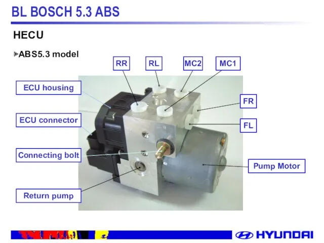
▶ABS5.3 model
HECU
▶ABS5.3 model
HECU
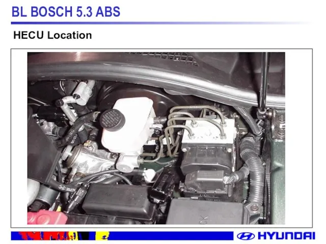
HECU Location
HECU Location
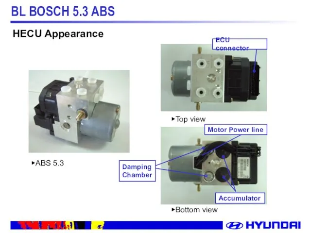
▶ABS 5.3
▶Top view
▶Bottom view
ECU connector
Accumulator
Damping
Chamber
Motor Power line
HECU Appearance
▶ABS 5.3
▶Top view
▶Bottom view
ECU connector
Accumulator
Damping
Chamber
Motor Power line
HECU Appearance
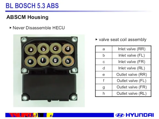
▶ Never Disassemble HECU
▶ valve seat coil assembly
ABSCM Housing
▶ Never Disassemble HECU
▶ valve seat coil assembly
ABSCM Housing
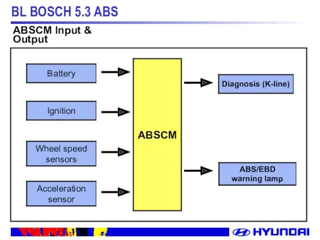
ABSCM Input & Output
ABSCM Input & Output
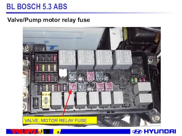
VALVE, MOTOR RELAY FUSE
Valve/Pump motor relay fuse
VALVE, MOTOR RELAY FUSE
Valve/Pump motor relay fuse
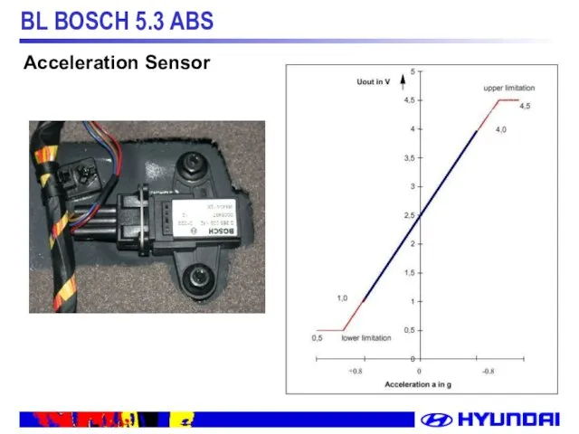
Acceleration Sensor
Acceleration Sensor
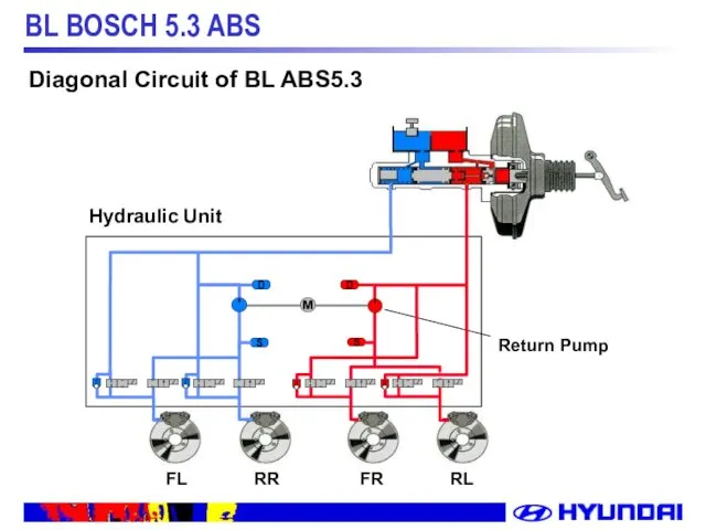
Return Pump
Hydraulic Unit
FL
RR
FR
RL
Diagonal Circuit of BL ABS5.3
Return Pump
Hydraulic Unit
FL
RR
FR
RL
Diagonal Circuit of BL ABS5.3
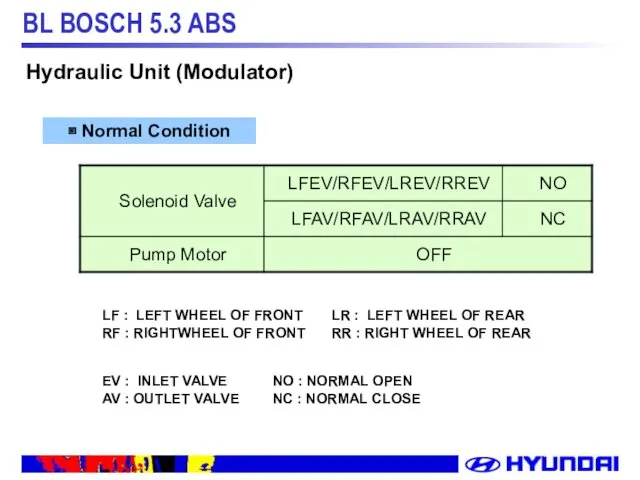
▣ Normal Condition
Hydraulic Unit (Modulator)
▣ Normal Condition
Hydraulic Unit (Modulator)
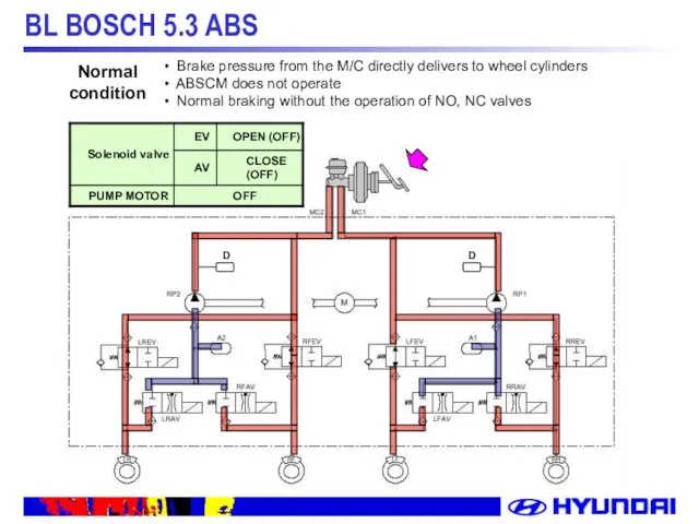
Brake pressure from the M/C directly delivers to wheel cylinders
Brake pressure from the M/C directly delivers to wheel cylinders
Stiff braking pressure → reduced friction, Wheel Lock-up tendency
ABSCM
Stiff braking pressure → reduced friction, Wheel Lock-up tendency
ABSCM
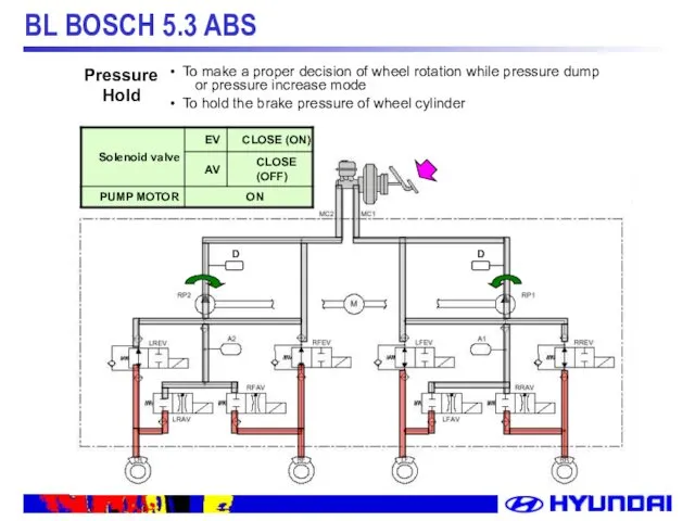
To make a proper decision of wheel rotation while pressure
To make a proper decision of wheel rotation while pressure

If a frictional force between tire and road surface increases,
If a frictional force between tire and road surface increases,
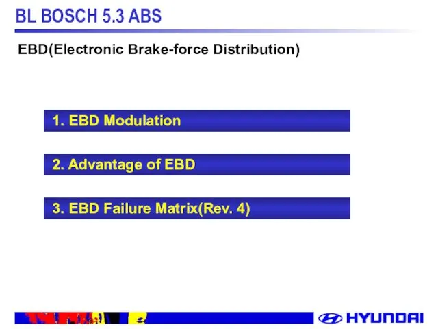
1. EBD Modulation
2. Advantage of EBD
3. EBD
1. EBD Modulation
2. Advantage of EBD
3. EBD
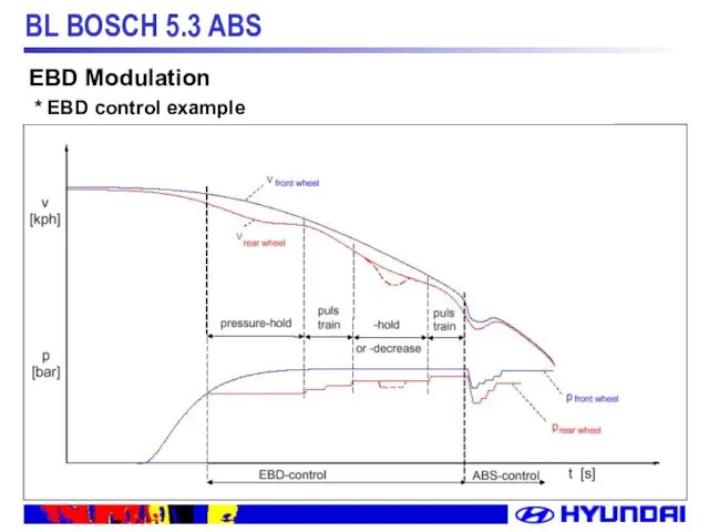
EBD Modulation
* EBD control example
EBD Modulation
* EBD control example
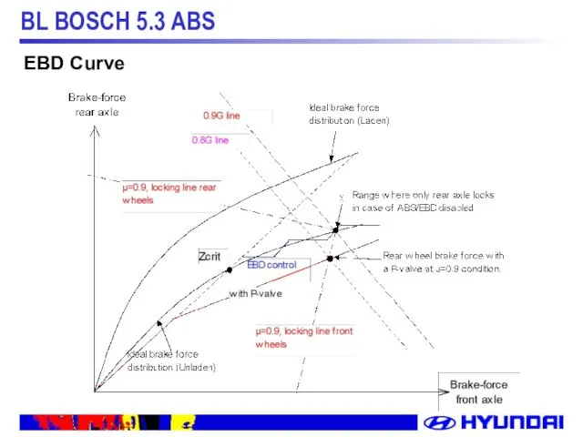
EBD Curve
EBD Curve
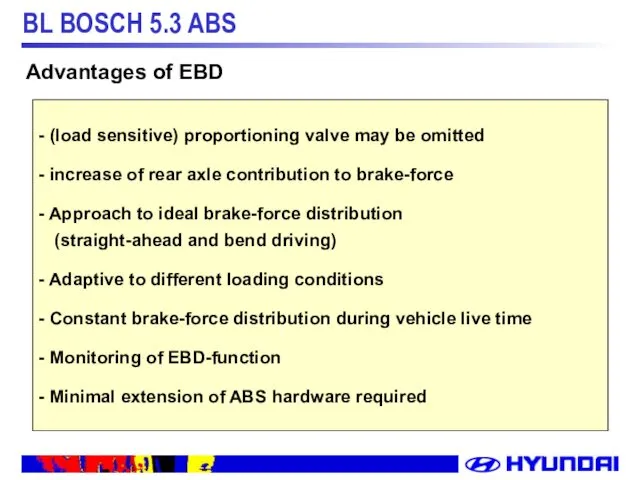
(load sensitive) proportioning valve may be omitted
increase of rear
(load sensitive) proportioning valve may be omitted
increase of rear
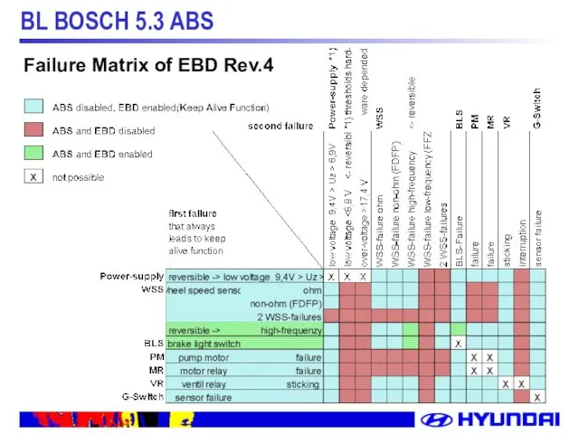
Failure Matrix of EBD Rev.4
Failure Matrix of EBD Rev.4
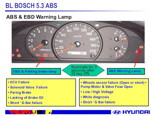
EBD & Parking brake lamp
• ECU Failure
• Solenoid Valve Failure
• Paring
EBD & Parking brake lamp
• ECU Failure
• Solenoid Valve Failure
• Paring
1. ABS & EBD Warning Lamp(Passive Type)
2. ABS
1. ABS & EBD Warning Lamp(Passive Type)
2. ABS
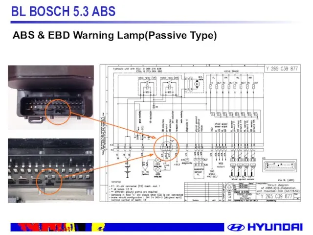
ABS & EBD Warning Lamp(Passive Type)
ABS & EBD Warning Lamp(Passive Type)
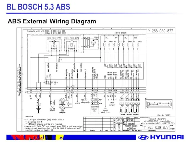
ABS External Wiring Diagram
ABS External Wiring Diagram
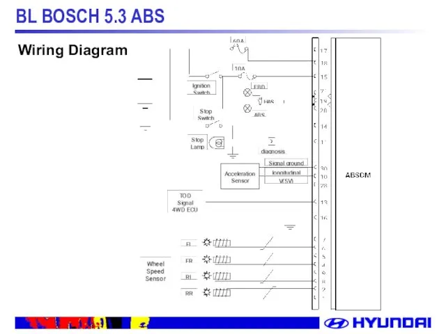
Wiring Diagram
Wiring Diagram
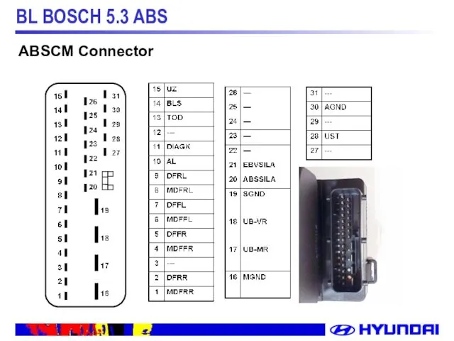
ABSCM Connector
ABSCM Connector
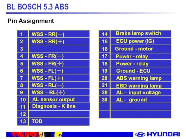
Pin Assignment
Pin Assignment
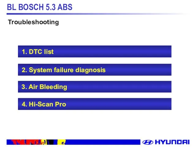
1. DTC list
2. System failure diagnosis
3. Air Bleeding
1. DTC list
2. System failure diagnosis
3. Air Bleeding
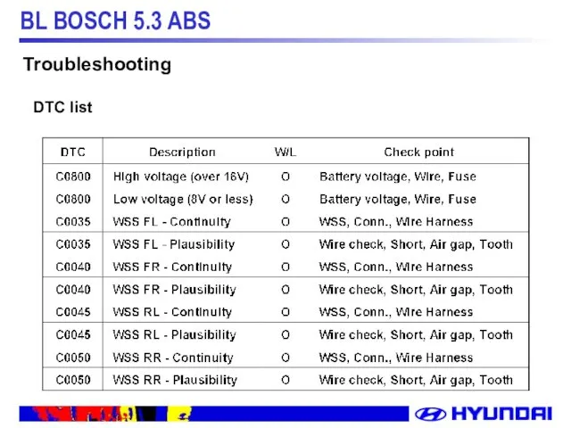
Troubleshooting
DTC list
Troubleshooting
DTC list
Troubleshooting
DTC list
Troubleshooting
DTC list
Troubleshooting
DTC list
Troubleshooting
DTC list
Detection period
A: Initial check
B: No ABS control
C: ABS in operation
D: Diagnostic
Detection period
A: Initial check
B: No ABS control
C: ABS in operation
D: Diagnostic
Failsafe after detecting failure
a) System down, ABS/EBD W/L, valve relay/solenoid valve
Failsafe after detecting failure
a) System down, ABS/EBD W/L, valve relay/solenoid valve
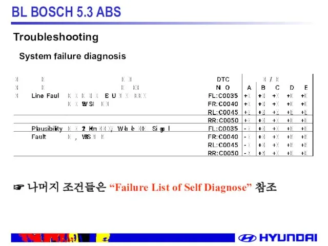
☞ 나머지 조건들은 “Failure List of Self Diagnose” 참조
Troubleshooting
System failure diagnosis
☞ 나머지 조건들은 “Failure List of Self Diagnose” 참조
Troubleshooting
System failure diagnosis
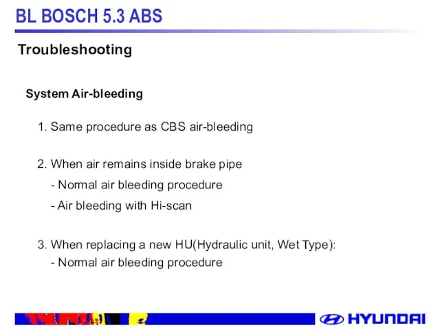
1. Same procedure as CBS air-bleeding
2. When air remains inside brake
1. Same procedure as CBS air-bleeding
2. When air remains inside brake
 Развитие энергетики республики Башкортостан
 Презентация по технологии Кафе 3 класс
 Гемопоэтические факторы роста
 Чудо - тесто
 физ.минутки на уроках
 Презентация 900 дней и ночей
 Применение свойств квадратного корня
 Моделирование систем. 2 лекция ББИ
 Презентация Белгородчина культурная
 Моя семья. Фотоальбом
 Родительское собрание Первые школьные отметки
 Данные аэродрома Астана. Классификация аэропорта. Технические данные аэропорта
 Создаём текст сочинения
 Мастер-класс по изготовлению корзинки из мыла и атласных лент
 Органикалық қосылыстардың жіктелуі
 Обучение сотрудников. Металлопрокат
 Понятие личность
 Презентация Шашечный турнир
 Интерактивная игра. Экологический калейдоскоп
 Машины постоянного тока
 Исторический роман
 Современная эпидемиологическая характеристика Дизентерии Зонне на территории Астраханской области
 Птицы. Певчие птицы. Пословицы и поговорки, мифы и легенды, загадки о птицах
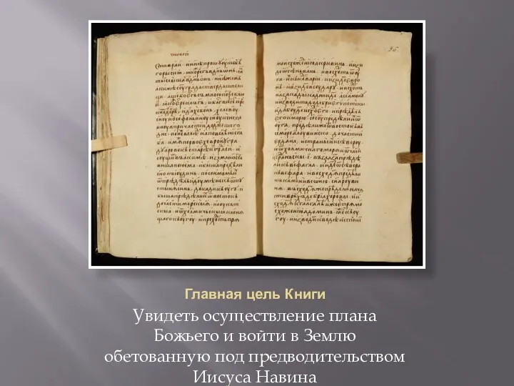 Книга Иисуса Навина
 Классный час Безопасный интернет
 Клуб Двойная навигация. Контроль давления. УЗИ. Нейростимулция
 Систематизация и обработка промыслового материала
 Северо-Западный ФО