- Dongguan Piny Automatic Technology Co. Ltd. The Robot selection

Содержание
- 2. The Robot selection The fixture Structure The Air cylinder The machine information 01 02 03 04
- 3. 1.The Robot Selection 1.The oblique arm type robot can just clamp the runner; it is much
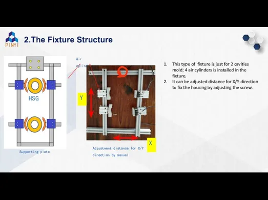
- 4. 2.The Fixture Structure HSG Air cylinder Supporting plate This type of fixture is just for 2
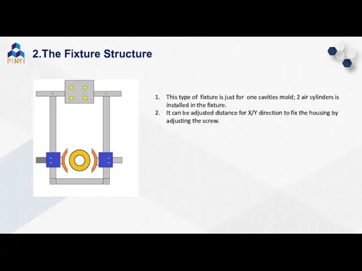
- 5. 2.The Fixture Structure This type of fixture is just for one cavities mold; 2 air cylinders
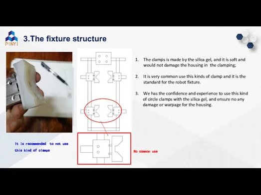
- 6. 3.The fixture structure The clamps is made by the silica gel, and it is soft and
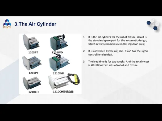
- 7. 3.The Air Cylinder It is the air cylinder for the robot fixture; also it is the
- 8. 4.The investment and plan
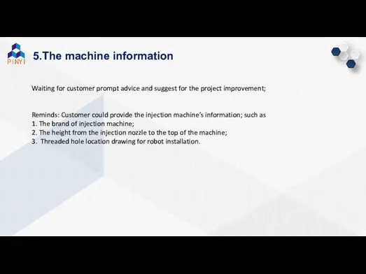
- 9. 5.The machine information Waiting for customer prompt advice and suggest for the project improvement; Reminds: Customer
- 10. 5.The machine information Safety door Injection barrel B A The plate C for installation of the
- 11. 5.The machine information Workshop’s travelling Crane The height of the travelling crane is 5m +in the
- 12. 6.The Gauge Information Please help to double confirm the Dim of the gage ring provided by
- 13. 6.The Gauge Information As the outside of ring is 0.30 smaller than before, so the inner
- 14. 7.The Robot signal connecting with machine +24V +24V 0V 0V Power 220V Use the multimeter to
- 15. 9.The information/decision provided by customer
- 16. 8.The mold improvement schedule
- 18. Скачать презентацию
The Robot selection
The fixture Structure
The Air cylinder
The machine information
01
02
03
04
05
Contents
CONTENTS
The investment
The Robot selection
The fixture Structure
The Air cylinder
The machine information
01
02
03
04
05
Contents
CONTENTS
The investment
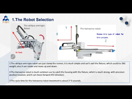
1.The Robot Selection
1.The oblique arm type robot can just clamp the
1.The Robot Selection
1.The oblique arm type robot can just clamp the
2.The Fixture Structure
HSG
Air cylinder
Supporting plate
This type of fixture is just for
2.The Fixture Structure
HSG
Air cylinder
Supporting plate
This type of fixture is just for
2.The Fixture Structure
This type of fixture is just for one cavities
2.The Fixture Structure
This type of fixture is just for one cavities
3.The fixture structure
The clamps is made by the silica gel, and
3.The fixture structure
The clamps is made by the silica gel, and
3.The Air Cylinder
It is the air cylinder for the robot
3.The Air Cylinder
It is the air cylinder for the robot
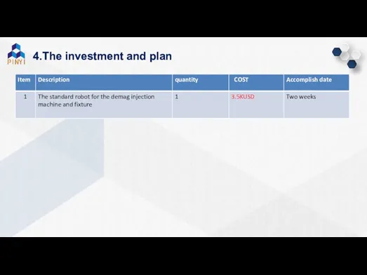
4.The investment and plan
4.The investment and plan
5.The machine information
Waiting for customer prompt advice and suggest for the
5.The machine information
Waiting for customer prompt advice and suggest for the
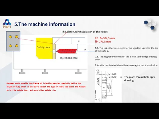
5.The machine information
Safety door
Injection barrel
B
A
The plate C for installation
5.The machine information
Safety door
Injection barrel
B
A
The plate C for installation
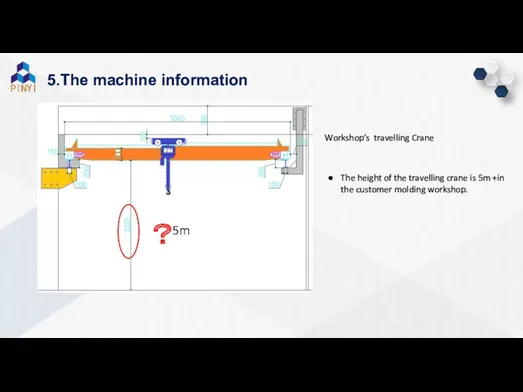
5.The machine information
Workshop’s travelling Crane
The height of the travelling crane is
5.The machine information
Workshop’s travelling Crane
The height of the travelling crane is
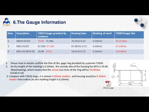
6.The Gauge Information
Please help to double confirm the Dim of the
6.The Gauge Information
Please help to double confirm the Dim of the
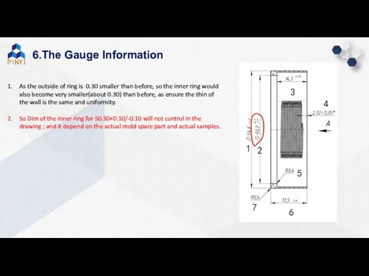
6.The Gauge Information
As the outside of ring is 0.30 smaller than
6.The Gauge Information
As the outside of ring is 0.30 smaller than
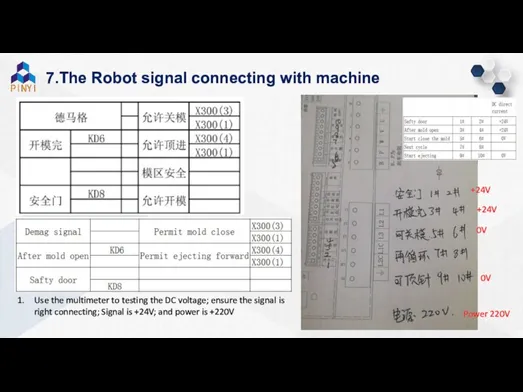
7.The Robot signal connecting with machine
+24V
+24V
0V
0V
Power 220V
Use the
7.The Robot signal connecting with machine
+24V
+24V
0V
0V
Power 220V
Use the
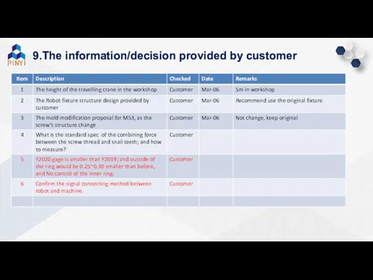
9.The information/decision provided by customer
9.The information/decision provided by customer
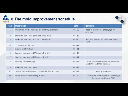
8.The mold improvement schedule
8.The mold improvement schedule
 Поздравляю с Новым годом
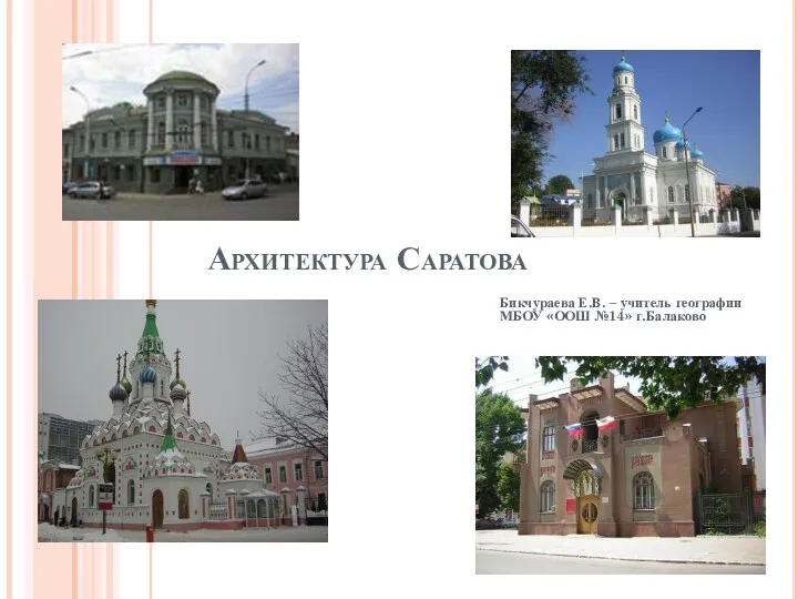 Архитектура Саратова
 Поле, його властивості
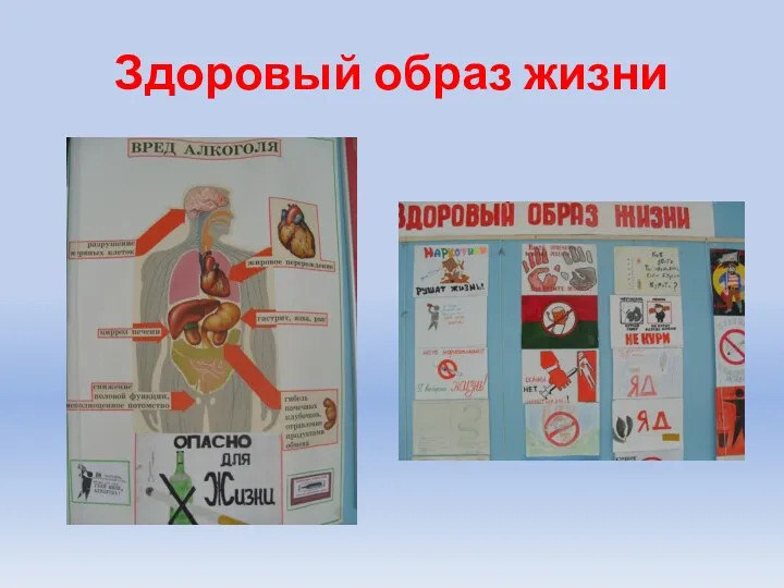 Здоровый образ жизни, мы против расизма
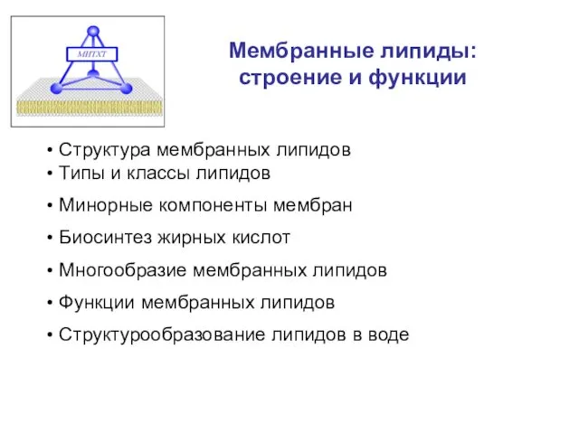 Мембранные липиды: строение и функции
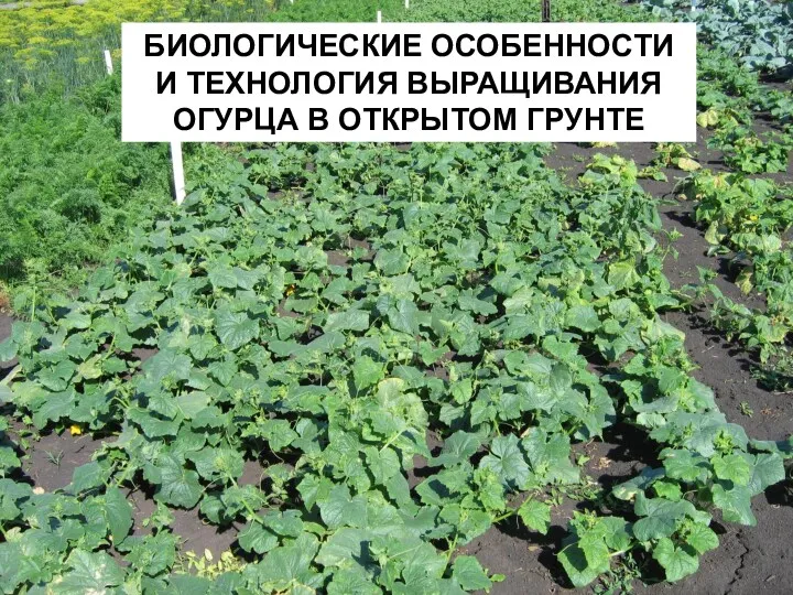 Биологические особенности и технология выращивания огурца в открытом грунте
 Презентация к уроку
 Приёмники оптического излучения
 Презентация к уроку Поэты Ставрополья о родном крае и о природе родного края
 Презентация С.Т.Аксаков - певец родной природы
 Ответственность в хозяйственном праве
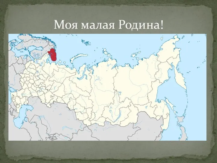 Классный час Моя малая Родина
 Радуга творчества
 Погода и климат
 Деталь беттерін металдармен қорытпалармен жабу
 Анализ портфеля акций
 Духовно-нравственное воспитание учащихся
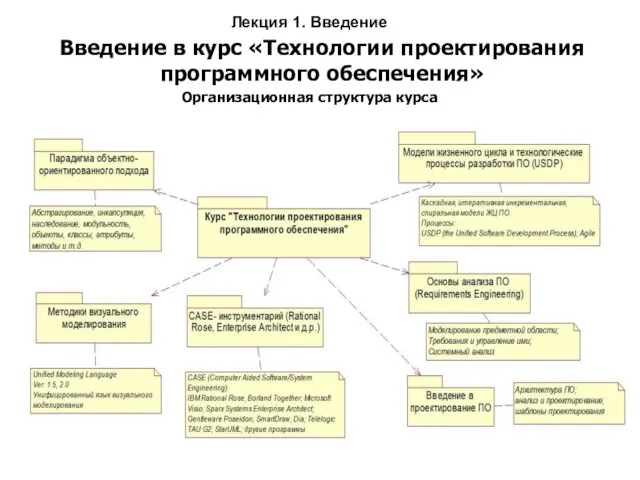 Основные элементы базовой нотации языка UML
 Церковь Одигитрии Смоленской (XVII в) - символ Вязьмы
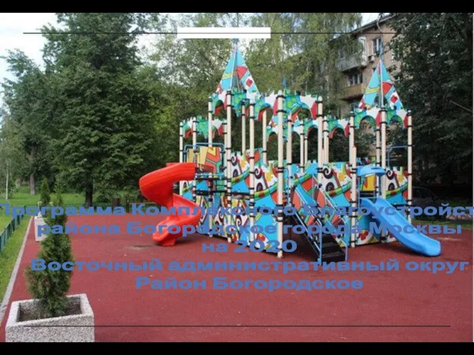 Благоустройство территории района Богородское города Москвы в 2020 г
 Наряд для семейного обеда (урок технологии в 6 классе)
 Санитарное просвещение и гигиеническое воспитание населения
 Презентация Заповеди Блаженствпо предмету ОПК
 Воронецкая (2)
 Помощь подростку в выборе профессии
 ПРЕЗЕНТАЦИЯ о животных
 Всероссийский образовательный командный турнир Знайки (2-4 классы)
 Промывочные агрегаты