- Kia Motors. EN Body Electrical

Содержание
- 2. CAN connection
- 3. All Door Override Unlocking
- 4. Inside Handle Safety Knob deleted CTR Facial : LOCK / UNLOCK located on center facial panel
- 5. Outside Handle for opening tail gate Tail gate outside handle : electric type Tail Gate Outside
- 6. Rear Seat Belt Remind Warning Passenger’s Seat Belt Reminder Mat Driver’s Seat Belt Cluster Seat Belt
- 7. Front Seat Belt Remind Control Driver’s SEAT BELT SW Passenger BELT SW Passenger’s Seat Belt Reminder
- 8. Seat Belt Remind Waning Control Driver Seat Belt Remind Warning Engine ON –> Unfasten seat belt
- 9. Heater & A/C Air Mode The 3 mode actuators (Vent, floor, defrost) allow an occupant to
- 10. Air Mode Select Button on FATCM Panel
- 11. Ambient Sensor
- 12. Logic cancel and selection (Manual A/C) A. Select DEF. mode B. Push Intake button 5 times
- 13. Temperature unit change User may choose the temperature indication between °C and °F. Press the auto
- 14. Diagnosis (using controller button) The FATC module self diagnosis test feature will detect electrical malfunction and
- 15. DTC list & failsafe
- 16. Auto Light Control Tail & Head Lamp Control Photo Sensor Light Switch BCM
- 17. Back Warning System Back warning buzzer Back warning control module Ultrasonic sensor
- 18. BWS, sensing range and warning method The warning is generated when the object is closed to
- 19. BWS Warning when ultra-sonic sensor is malfunction After electric power is supplied, if the gear shift
- 20. Safety Power Window P/WDW MOTOR P/WDW SW : It is SAFETY specification at 'AUTO' character application
- 21. 15) SUNROOF SYSTEM
- 22. Trip Computer Monitor Display Item ● Trip Information - DTE (Distance to Empty) - Elapsed time
- 23. Trip Computer Input/Output Signal Battery Back up Ignition Illumination Ambient Temp Sensor Injection Signal Fuel Sender
- 24. Trip Computer LCD Monitor Trip information Calendar & Clock Audio information Ambient temperature Freezing warning information
- 25. Trip Information of Distance to Empty ◑ Connection Input Source Vehicle Speed Sensor Tachometer Injector Pulse(80mCC/1
- 26. Distance to Empty Block Diagram Speed Signal M/Time : 25ms. Injection Signal 80㎕ X n_Pulse Speed
- 27. Distance to Empty Logic Flow Chart (Data Regeneration) 500 m In case Normal
- 28. Distance to Empty Logic Flow Chart (Data Regeneration)
- 29. Distance to Empty Data Regeneration after Fuel Charge § Fuel charged with key Off : Fuel
- 30. Distance to Empty Data Regeneration after Fuel Charge § Fuel charged with key ON : Fuel
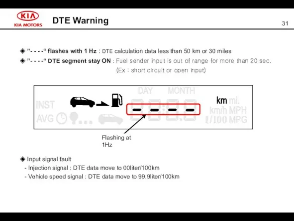
- 31. DTE Warning ◆ ”- - - -“ flashes with 1 Hz : DTE calculation data less
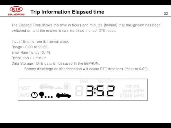
- 32. Trip Information Elapsed time The Elapsed Time shows the time in hours and minutes (hh:mm) that
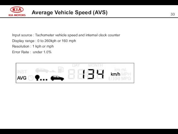
- 33. Average Vehicle Speed (AVS) Input source : Tachometer vehicle speed and internal clock counter Display range
- 34. Average Fuel Consumption (AFC) ● Input source : Injection signal & Vehicle speed signal ● Data
- 35. Average Fuel Consumption (AFC) Distance 200km Normal VSS problem Inj. problem Sender problem F E
- 36. Instantaneous Fuel Consumption (IFC) The microprocessor calculates the instantaneous fuel consumption from the instantaneous fuel used
- 37. Unit Conversion on the display screen
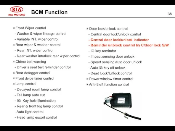
- 38. BCM Function ▣ Front Wiper control - Washer & wiper lineage control - Variable INT. wiper
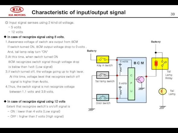
- 39. Characteristic of input/output signal ◎ Input signal senses using 2 kind of voltage. - 5 volts
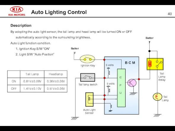
- 40. Auto Lighting Control Description By adopting the auto light sensor, the tail lamp and head lamp
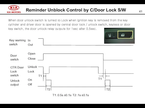
- 41. Reminder Unblock Control by C/Door Lock S/W When door unlock switch is turned to Lock when
- 43. Скачать презентацию
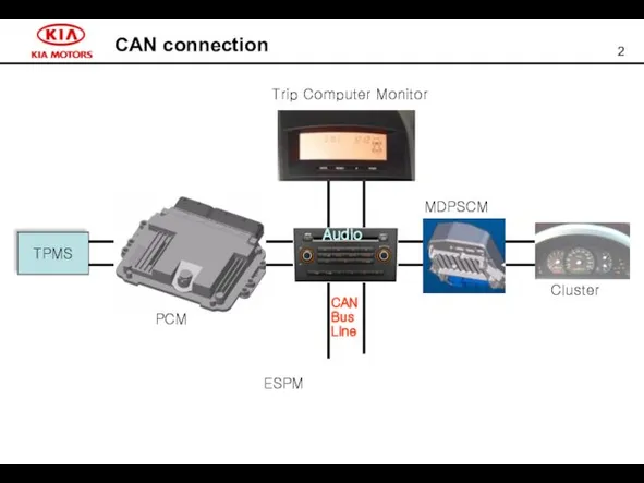
CAN connection
CAN connection
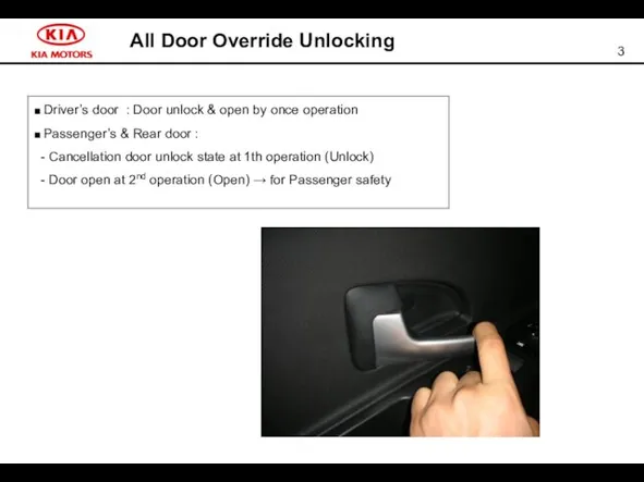
All Door Override Unlocking
All Door Override Unlocking
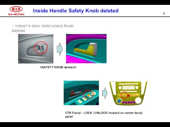
Inside Handle Safety Knob deleted
CTR Facial : LOCK
Inside Handle Safety Knob deleted
CTR Facial : LOCK
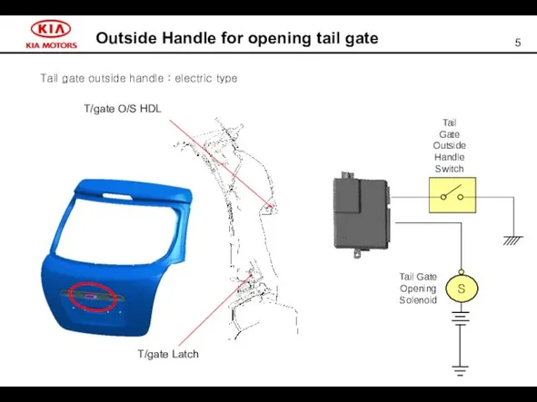
Outside Handle for opening tail gate
Tail gate outside handle : electric
Outside Handle for opening tail gate
Tail gate outside handle : electric
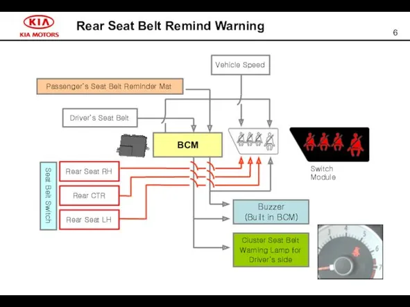
Rear Seat Belt Remind Warning
Passenger’s Seat Belt Reminder Mat
Driver’s Seat Belt
Cluster
Rear Seat Belt Remind Warning
Passenger’s Seat Belt Reminder Mat
Driver’s Seat Belt
Cluster
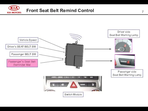
Front Seat Belt Remind Control
Driver’s SEAT BELT SW
Passenger BELT SW
Passenger’s Seat
Front Seat Belt Remind Control
Driver’s SEAT BELT SW
Passenger BELT SW
Passenger’s Seat
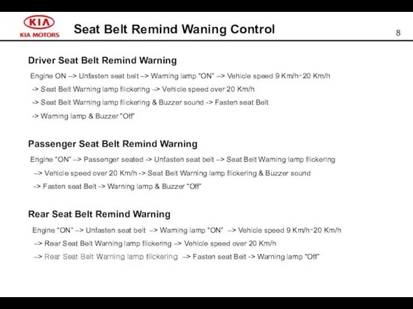
Seat Belt Remind Waning Control
Driver Seat Belt Remind Warning
Engine ON
Seat Belt Remind Waning Control
Driver Seat Belt Remind Warning
Engine ON
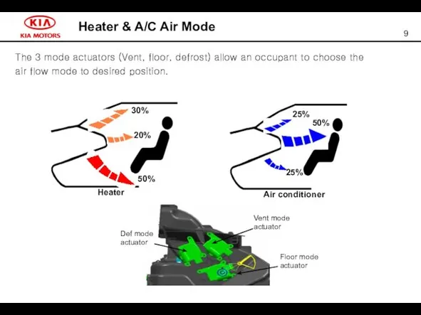
Heater & A/C Air Mode
The 3 mode actuators (Vent, floor, defrost)
Heater & A/C Air Mode
The 3 mode actuators (Vent, floor, defrost)
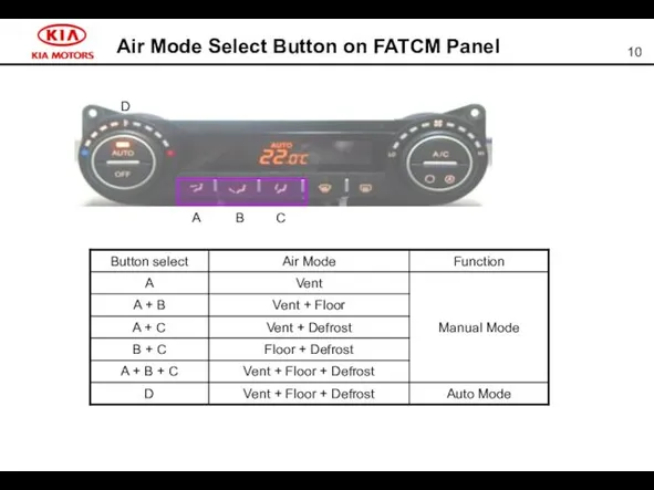
Air Mode Select Button on FATCM Panel
Air Mode Select Button on FATCM Panel
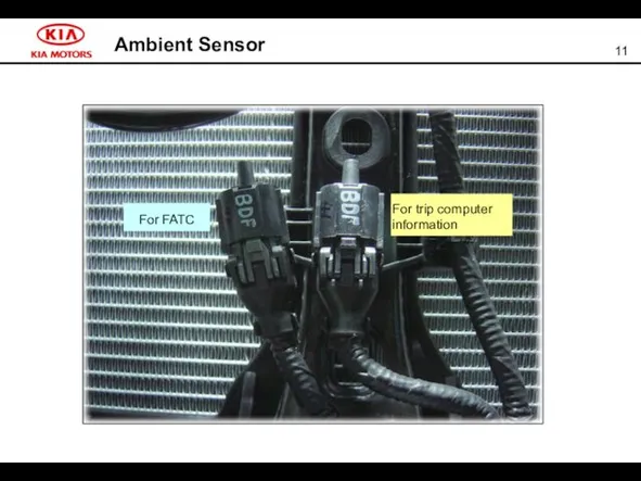
Ambient Sensor
Ambient Sensor
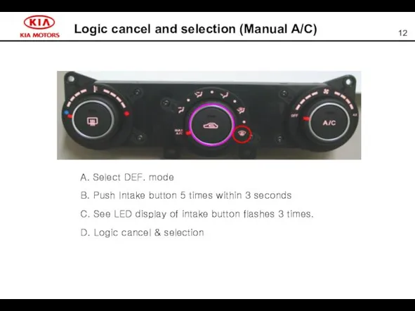
Logic cancel and selection (Manual A/C)
A. Select DEF. mode
B. Push
Logic cancel and selection (Manual A/C)
A. Select DEF. mode
B. Push
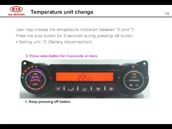
Temperature unit change
User may choose the temperature indication between °C and
Temperature unit change
User may choose the temperature indication between °C and
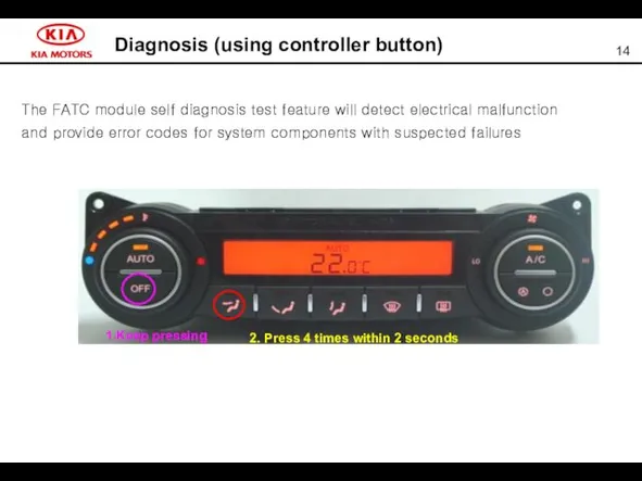
Diagnosis (using controller button)
The FATC module self diagnosis test feature will
Diagnosis (using controller button)
The FATC module self diagnosis test feature will
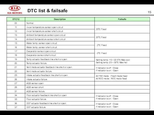
DTC list & failsafe
DTC list & failsafe
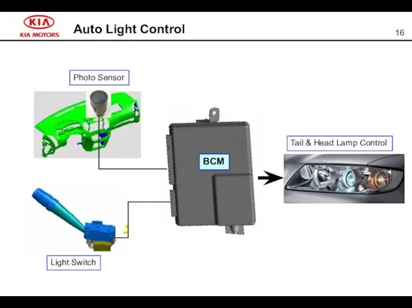
Auto Light Control
Tail & Head Lamp Control
Photo Sensor
Light Switch
BCM
Auto Light Control
Tail & Head Lamp Control
Photo Sensor
Light Switch
BCM
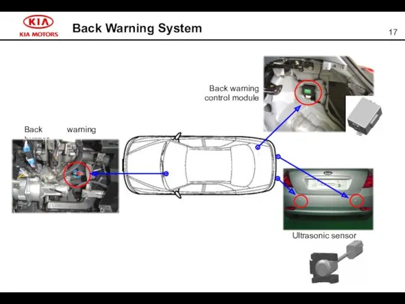
Back Warning System
Back warning buzzer
Back warning
control module
Ultrasonic sensor
Back Warning System
Back warning buzzer
Back warning
control module
Ultrasonic sensor
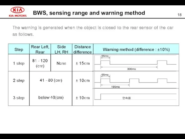
BWS, sensing range and warning method
The warning is generated when the
BWS, sensing range and warning method
The warning is generated when the
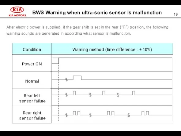
BWS Warning when ultra-sonic sensor is malfunction
After electric power is supplied,
BWS Warning when ultra-sonic sensor is malfunction
After electric power is supplied,
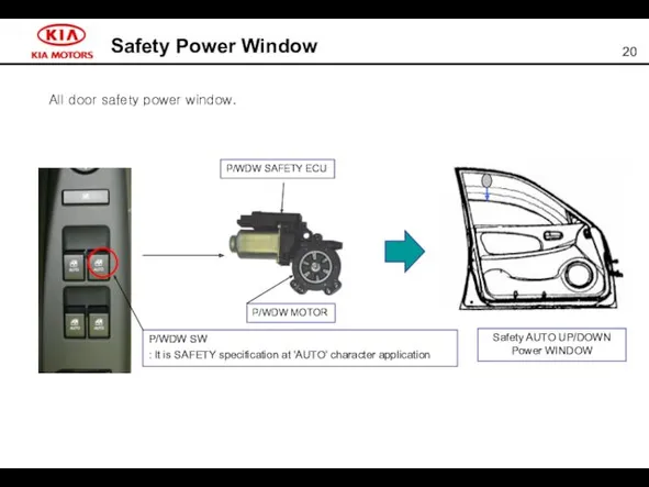
Safety Power Window
P/WDW MOTOR
P/WDW SW
: It is SAFETY specification at 'AUTO'
Safety Power Window
P/WDW MOTOR
P/WDW SW
: It is SAFETY specification at 'AUTO'
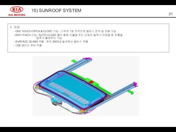
15) SUNROOF SYSTEM
15) SUNROOF SYSTEM
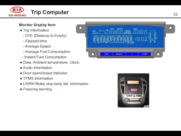
Trip Computer
Monitor Display Item
● Trip Information
- DTE (Distance
Trip Computer
Monitor Display Item
● Trip Information
- DTE (Distance
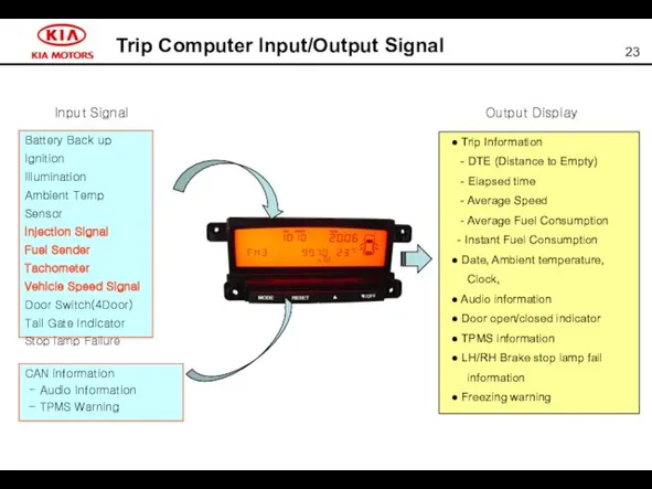
Trip Computer Input/Output Signal
Battery Back up
Ignition
Illumination
Ambient Temp Sensor
Injection Signal
Fuel Sender
Tachometer
Vehicle Speed
Trip Computer Input/Output Signal
Battery Back up
Ignition
Illumination
Ambient Temp Sensor
Injection Signal
Fuel Sender
Tachometer
Vehicle Speed
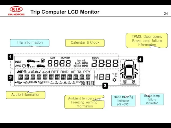
Trip Computer LCD Monitor
Trip information
Calendar & Clock
Audio information
Ambient temperature Freezing warning
Trip Computer LCD Monitor
Trip information
Calendar & Clock
Audio information
Ambient temperature Freezing warning
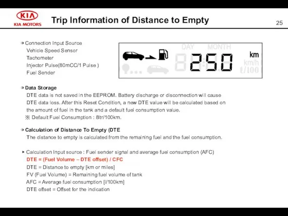
Trip Information of Distance to Empty
◑ Connection Input Source
Vehicle Speed
Trip Information of Distance to Empty
◑ Connection Input Source
Vehicle Speed
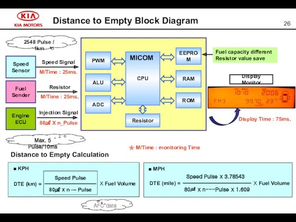
Distance to Empty Block Diagram
Speed Signal
M/Time : 25ms.
Injection Signal
80㎕ X n_Pulse
Speed
Sensor
Engine
ECU
CPU
Resistor
RAM
ROM
EEPROM
ADC
ALU
PWM
MICOM
Resistor
M/Time
Distance to Empty Block Diagram
Speed Signal
M/Time : 25ms.
Injection Signal
80㎕ X n_Pulse
Speed
Sensor
Engine
ECU
CPU
Resistor
RAM
ROM
EEPROM
ADC
ALU
PWM
MICOM
Resistor
M/Time
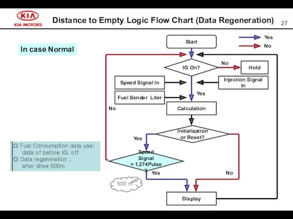
Distance to Empty Logic Flow Chart (Data Regeneration)
500 m
In case Normal
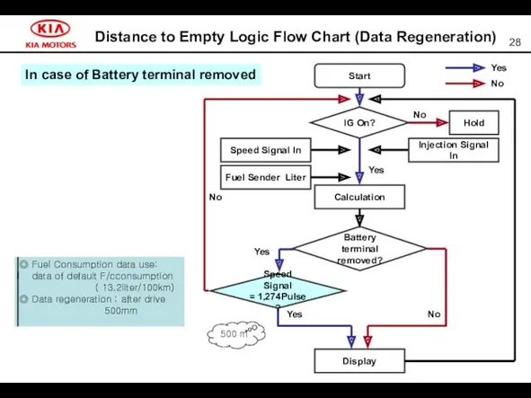
Distance to Empty Logic Flow Chart (Data Regeneration)
500 m
In case Normal
Distance to Empty Logic Flow Chart (Data Regeneration)
Distance to Empty Logic Flow Chart (Data Regeneration)
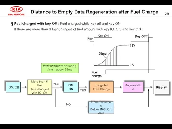
Distance to Empty Data Regeneration after Fuel Charge
§ Fuel charged with
Distance to Empty Data Regeneration after Fuel Charge
§ Fuel charged with
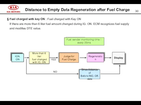
Distance to Empty Data Regeneration after Fuel Charge
§ Fuel charged with
Distance to Empty Data Regeneration after Fuel Charge
§ Fuel charged with
DTE Warning
◆ ”- - - -“ flashes with 1 Hz :
DTE Warning
◆ ”- - - -“ flashes with 1 Hz :
Trip Information Elapsed time
The Elapsed Time shows the time in hours
Trip Information Elapsed time
The Elapsed Time shows the time in hours
Average Vehicle Speed (AVS)
Input source : Tachometer vehicle speed and
Average Vehicle Speed (AVS)
Input source : Tachometer vehicle speed and
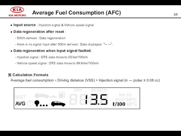
Average Fuel Consumption (AFC)
● Input source : Injection signal & Vehicle
Average Fuel Consumption (AFC)
● Input source : Injection signal & Vehicle
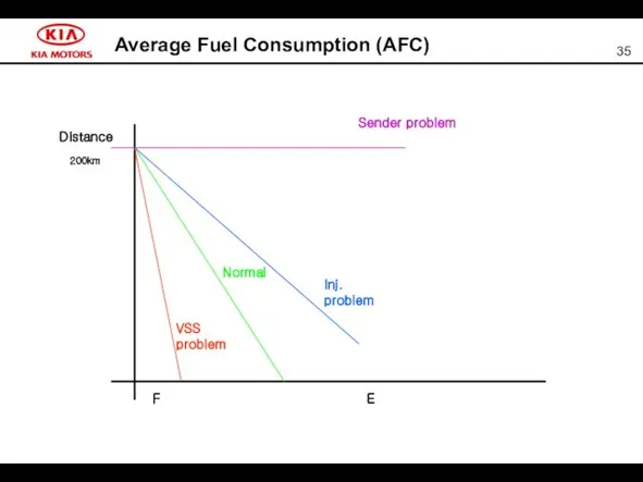
Average Fuel Consumption (AFC)
Distance
200km
Normal
VSS
problem
Inj.
problem
Sender problem
F E
Average Fuel Consumption (AFC)
Distance
200km
Normal
VSS
problem
Inj.
problem
Sender problem
F E
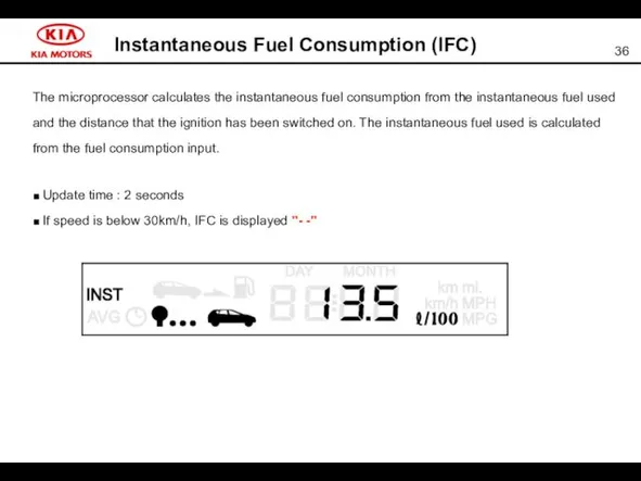
Instantaneous Fuel Consumption (IFC)
The microprocessor calculates the instantaneous fuel consumption
Instantaneous Fuel Consumption (IFC)
The microprocessor calculates the instantaneous fuel consumption
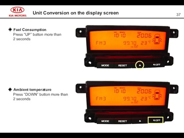
Unit Conversion on the display screen
Unit Conversion on the display screen
BCM Function
▣ Front Wiper control
- Washer & wiper lineage
BCM Function
▣ Front Wiper control
- Washer & wiper lineage
Characteristic of input/output signal
◎ Input signal senses using 2 kind of
Characteristic of input/output signal
◎ Input signal senses using 2 kind of
Auto Lighting Control
Description
By adopting the auto light sensor, the tail lamp
Auto Lighting Control
Description
By adopting the auto light sensor, the tail lamp
Reminder Unblock Control by C/Door Lock S/W
When door unlock switch is
Reminder Unblock Control by C/Door Lock S/W
When door unlock switch is
 Презентация к Дню матери
 Национальное богатство: концепция, определение, классификация
 Работа с программой Octopus и сайтом статистики
 Бытовые электроприборы на кухне
 Глобальный диктант. Траектории Аналитика, наука и инновации Международные связи
 литературное караоке
 Здоровые дети в здоровой семье
 Россия - родина моя.
 Планирование воспитательного процесса: сущность, содержание и технология
 Элементная база современных электронных устройств
 Конспект и презентация к занятию внеурочной деятельности Что означают наши имена
 Презентация. Гендерный подход в воспитании дошкольников.
 Неревматические кардиты и вегетососудистая дистония у детей
 Составление схем автоматического управления электроприводами, работающими в заданной последовательности
 Презентация по теме :КОМПЕТЕНТНОСТНО-ОРИЕНТИРОВАННЫЕ ЗАДАНИЯ НА УРОКАХ МАТЕМАТИКИ В НАЧАЛЬНОЙ ШКОЛЕ КАК СРЕДСТВО ФОРМИРОВАНИЯ КОНТРОЛЬНО – ОЦЕНОЧНЫХ ДЕЙСТВИЙ.
 Внутренний водный транспорт
 Корень. Внешнее и внутреннее строение корня
 Решение одной из глобальных проблем человечества - экологическая проблема
 Ко Дню защиты детей. Мастер-класс по изготовлению открытки
 ПрезентацияНестандартные формы уроков
 Дворцовые перевороты
 Класс Пресмыкающиеся
 Factori care influenţează calitatea educaţiei
 Презентация Герои Отечества.
 Институт контрассигнатуры в зарубежных странах
 Россыпные месторождения
 Плетение из бумаги. Коврик
 ҚарМУ-нің Автономды жылыту жүйесі