- Laser technologies of Triniti JSC

Содержание
- 2. Mobile laser technological complex (MLTC) Solutions for elimination of emergency oil and oil-product spills in various
- 3. 1. Mobile laser technological complex
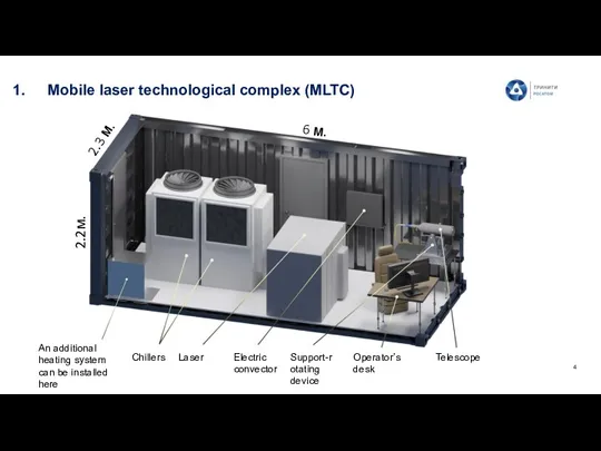
- 4. Mobile laser technological complex (MLTC) 2.2м. 2.3 м. 6 м. An additional heating system can be
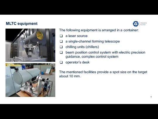
- 5. MLTC equipment The following equipment is arranged in a container: a laser source a single-channel forming
- 6. MLTC performance capabilities Remote laser cutting using transport optical fiber (up to 100 m): fragmentation of
- 7. MLTC technical characteristics Up to 50 kW Laser output power Up to 150 kW Power supply
- 8. Possible scenarios for the MLTC use: fragmentation of elements of the NPP reactor vessel The technology
- 9. Feasibility demonstration Test concrete block 780*660*510 mm Cutting of thick-walled metal imitating the body of a
- 10. Examples of laser cutting of structures destroyed in a gas well accident MLTK-20 complex, created in
- 11. Main application areas Fragmentation of the NPP equipment Fragmentation of large-sized thick-walled metal and concrete building
- 12. 2. Solutions for elimination of emergency oil and oil-product spills in various conditions, including the Arctic
- 13. Federal law “On Amendments to Article 46 of the Federal Law "On Environmental Protection“” and certain
- 14. Application option Operational installation of booms of the oil spill guard Laser ignition from the MLTC
- 15. Equipment outline Laser – 850*800*1100 – 140 kg. Chiller – 400*480*550 – 46 kg. Battery –
- 16. Approximate cost of developing the complex and providing services Terms: Development of the complex will take
- 17. Successful demonstration of oil spill elimination Resistant oil emulsion on sand Resistant oil emulsion on water
- 18. Advantages of laser oil spill elimination Safety for personnel, due to remote exposure (in the case
- 19. Pros and cons of the applied methods
- 20. The following combustion products are formed during the combustion of the oil products:
- 21. Potential customers Oil and gas industries: PJSC «Tatneft» n.a. V.D. Shashin PJSC «Lukoil» PJSC «Gazprom» PJSC
- 22. 3. Mobile laser technological complex for underwater cutting
- 23. Underwater laser cutting A Mobile Laser Technology Module (MLTC) has been created in TRINITI JSC. One
- 24. Implementation scheme 1. Laser source 2. Gas source (cylinder or compressor) ρair > ρwater 3. Control
- 25. Technology comparison
- 26. Functions of the underwater robotic arm The robotic arm is to be developed according to the
- 28. Скачать презентацию
Mobile laser technological complex (MLTC)
Solutions for elimination of emergency oil and
Mobile laser technological complex (MLTC)
Solutions for elimination of emergency oil and
1. Mobile laser technological complex
1. Mobile laser technological complex
Mobile laser technological complex (MLTC)
2.2м.
2.3 м.
6 м.
An additional heating system can
Mobile laser technological complex (MLTC)
2.2м.
2.3 м.
6 м.
An additional heating system can
MLTC equipment
The following equipment is arranged in a container:
a laser
MLTC equipment
The following equipment is arranged in a container:
a laser
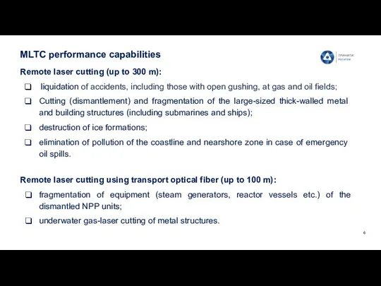
MLTC performance capabilities
Remote laser cutting using transport optical fiber (up to
MLTC performance capabilities
Remote laser cutting using transport optical fiber (up to
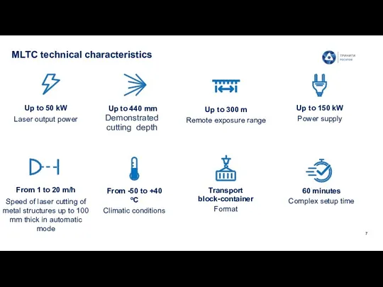
MLTC technical characteristics
Up to 50 kW
Laser output power
Up to 150 kW
Power
MLTC technical characteristics
Up to 50 kW
Laser output power
Up to 150 kW
Power
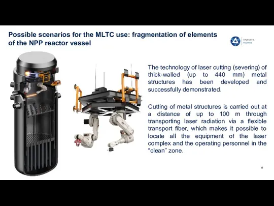
Possible scenarios for the MLTC use: fragmentation of elements of the
Possible scenarios for the MLTC use: fragmentation of elements of the
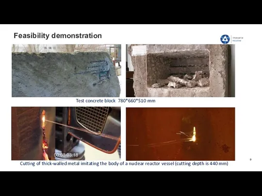
Feasibility demonstration
Test concrete block 780*660*510 mm
Cutting of thick-walled metal imitating the
Feasibility demonstration
Test concrete block 780*660*510 mm
Cutting of thick-walled metal imitating the
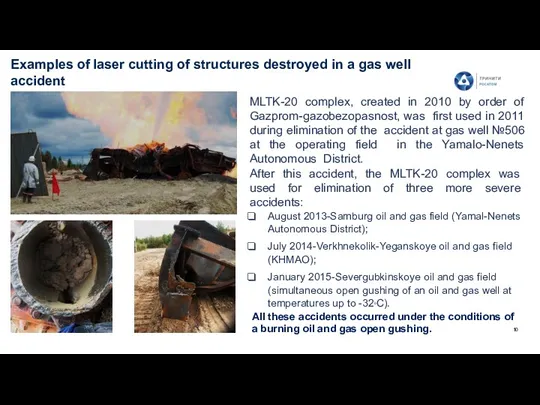
Examples of laser cutting of structures destroyed in a gas well
Examples of laser cutting of structures destroyed in a gas well
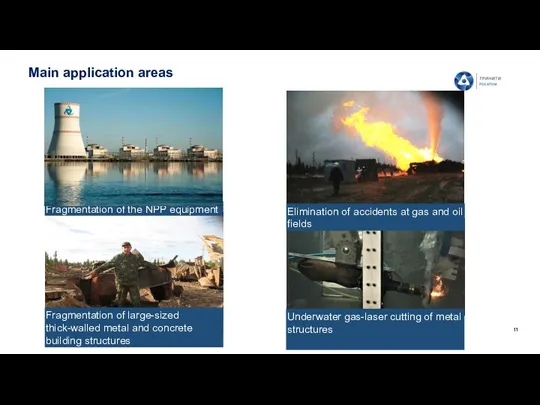
Main application areas
Fragmentation of the NPP equipment
Fragmentation of large-sized thick-walled metal
Main application areas
Fragmentation of the NPP equipment
Fragmentation of large-sized thick-walled metal
2. Solutions for elimination of emergency oil and oil-product spills in
2. Solutions for elimination of emergency oil and oil-product spills in
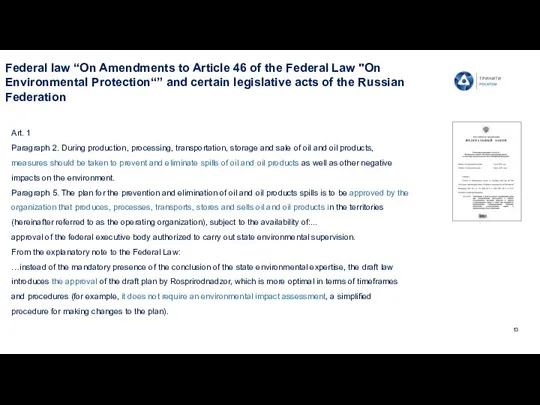
Federal law “On Amendments to Article 46 of the Federal Law
Federal law “On Amendments to Article 46 of the Federal Law
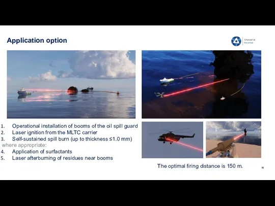
Application option
Operational installation of booms of the oil spill guard
Laser ignition
Application option
Operational installation of booms of the oil spill guard
Laser ignition
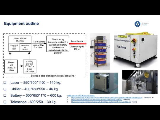
Equipment outline
Laser – 850*800*1100 – 140 kg.
Chiller – 400*480*550 – 46
Equipment outline
Laser – 850*800*1100 – 140 kg.
Chiller – 400*480*550 – 46
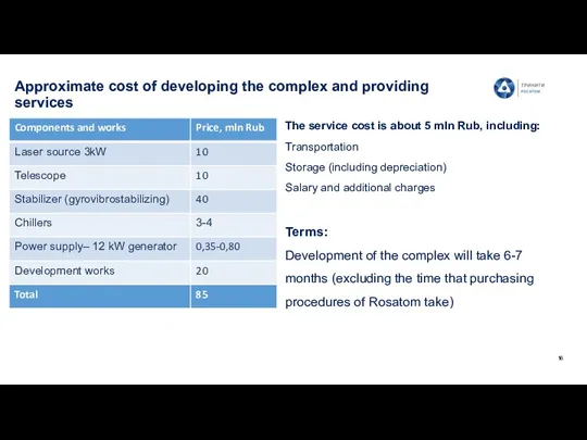
Approximate cost of developing the complex and providing services
Terms:
Development of the
Approximate cost of developing the complex and providing services
Terms:
Development of the
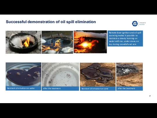
Successful demonstration of oil spill elimination
Resistant oil emulsion on sand
Resistant oil
Successful demonstration of oil spill elimination
Resistant oil emulsion on sand
Resistant oil
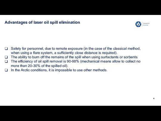
Advantages of laser oil spill elimination
Safety for personnel, due to remote
Advantages of laser oil spill elimination
Safety for personnel, due to remote
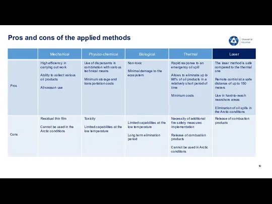
Pros and cons of the applied methods
Pros and cons of the applied methods
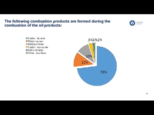
The following combustion products are formed during the combustion of the
The following combustion products are formed during the combustion of the
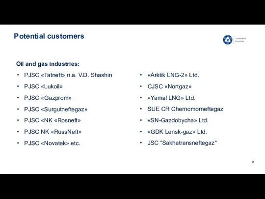
Potential customers
Oil and gas industries:
PJSC «Tatneft» n.a. V.D. Shashin
PJSC «Lukoil»
PJSC «Gazprom»
PJSC
Potential customers
Oil and gas industries:
PJSC «Tatneft» n.a. V.D. Shashin
PJSC «Lukoil»
PJSC «Gazprom»
PJSC
3. Mobile laser technological complex for underwater cutting
3. Mobile laser technological complex for underwater cutting
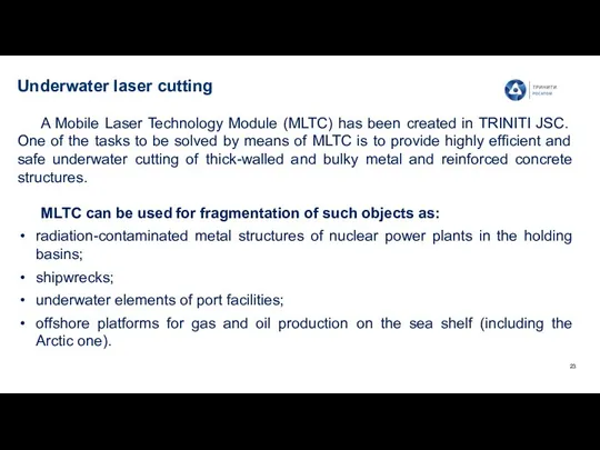
Underwater laser cutting
A Mobile Laser Technology Module (MLTC) has been
Underwater laser cutting
A Mobile Laser Technology Module (MLTC) has been
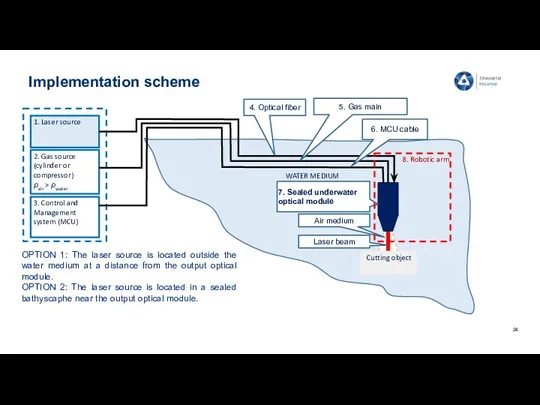
Implementation scheme
1. Laser source
2. Gas source (cylinder or compressor)
ρair > ρwater
3.
Implementation scheme
1. Laser source
2. Gas source (cylinder or compressor)
ρair > ρwater
3.
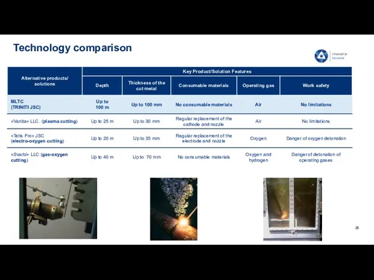
Technology comparison
Technology comparison
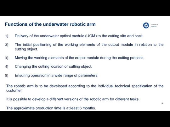
Functions of the underwater robotic arm
The robotic arm is to be
Functions of the underwater robotic arm
The robotic arm is to be
 Работа под управлением ОС Windows
 Многоэтажные промышленные здания
 f-6a699244
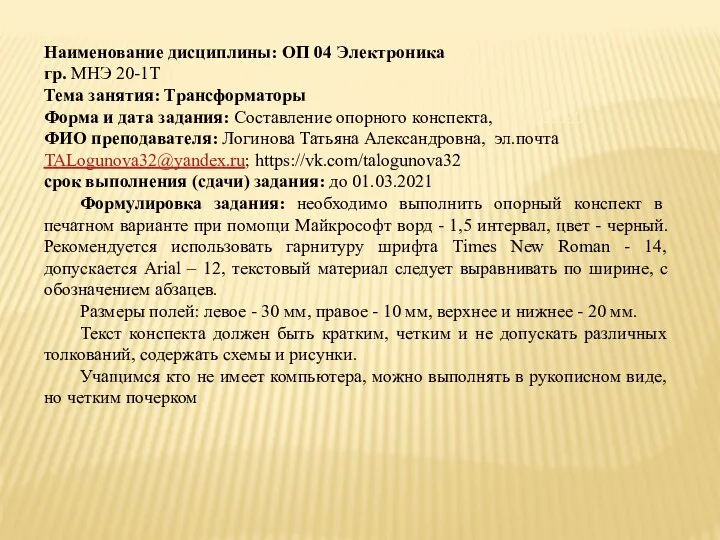 Трансформаторы. Устройство трансформаторов
 Внеурочная деятельность 4 класс. Презентация Умелые руки (мини-коробка) Диск
 Разноцветный маркетинг
 Метапредметная игра Самый умный
 Лабораторная работа: изучение элементов бурильной колонны
 Визуально-оптический метод контроля
 Ультразвук и инфразвук. (9 класс)
 Бурение скважин. (Тема 1.4)
 9 мая - День победы!
 Умножение дробей. 6 класс
 Симбиотикалық емес аэробты және анаэробты азотофиксаторлар
 Викторина. Фотографии
 Презентация к уроку Химические свойства металлов
 Реализация образовательной области Физическая культура в соответствии с ФГТ ( итоги года)
 Трубопроводный транспорт нефти и газа
 Развитие речи на уроках русского языка в рамках реализации ФГОС
 Отчеты главы города Нефтеюганска о результатах своей деятельности и результатах деятельности администрации города
 Конкурс переводчиков
 Решение уравнений. 7 класс
 Знаменитости умершие от употребления наркотиков-1
 Портфолио музыкального руководителя.
 Презентация к родительскому собранию Как здорово, что есть семья
 презентация к статье Организация внеурочной деятельности в начальной школе.
 Комплексные меры борьбы с сорняками в посевах полевых культур. (Лекция 6)
 Теория колебаний