- MIG 200P service manual

Содержание
- 2. Catalogue 1、Introduction of working principle 2、Introduction of main circuit(parts different from MMA) 3、Introduction of control circuit(parts
- 3. 1、Introduction of working principle
- 4. Working principle
- 5. System chart SOFT START
- 9. 2、Introduction of main circuit(parts different from MMA)
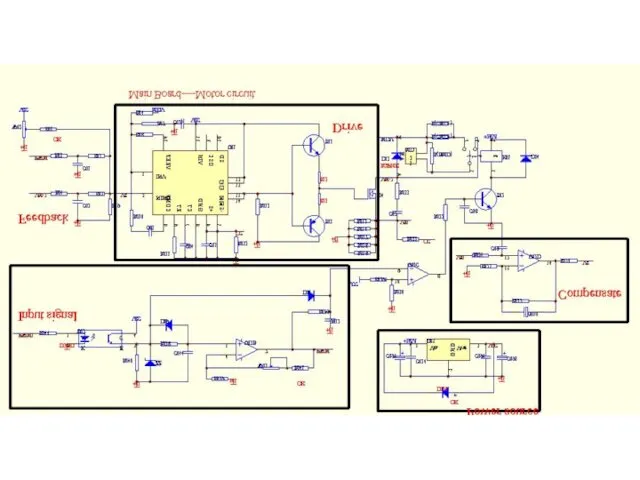
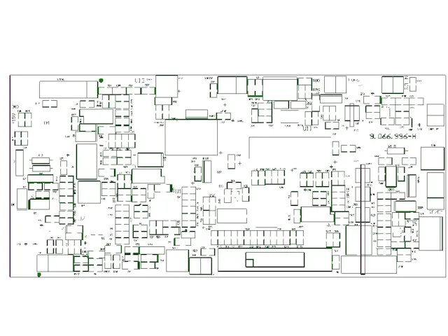
- 11. View of main board
- 12. Photo of main board
- 13. Photo of main PCB AC rectifier Motor driver circuit
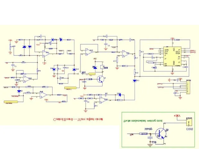
- 14. 3、Introduction of control circuit(parts different from MMA)
- 17. WVIN IGBT OT Gun QF/DY Drive Power CR NTCS Funs IFB PWM MB Imax Imin W2
- 18. DRIVE--Connected with main board to provide drive signal for discrete IGBT. Pin 1---- +15V;Pin 2~5---- Drive
- 19. IGBT OT--Connected with the IGBT NTC to provide over-temperature signal for MCU. WVIN--Connected with the output
- 20. Imax—used to adjust maximum welding current (MMA). Imin—used to adjust minimum welding current (MMA). A—used to
- 21. 4、Introduction of panel circuit
- 22. Electrical drawing of panel board
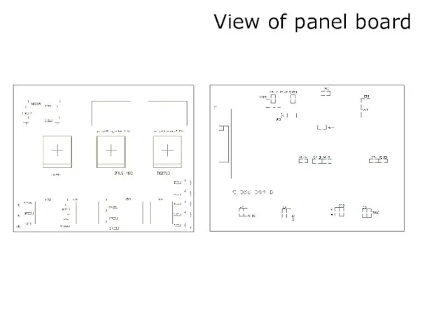
- 23. View of panel board
- 24. Photo of panel board
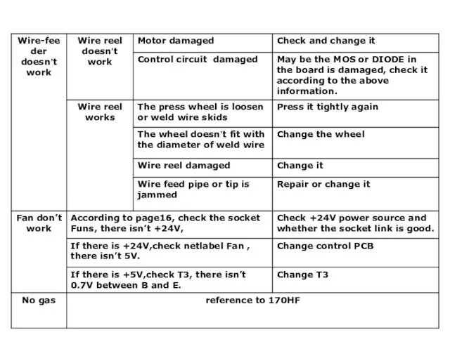
- 25. 5、Troubleshooting Series A: Troubles about panel display Series B: Troubles about power system
- 26. A、Presentation of panel Power display Over-temperature or Over-current alarm Potentiometer Weld mode display
- 27. Motor drive circuit In Main PCB WD5--Max speed adjust WD2--Min speed adjust Between the two Pins,
- 28. Test point wave Point A wave :The PWM wave from digital control PCB
- 29. Point B wave :The PWM set point from 6P of U02 Point C wave :The drive
- 30. Point F wave : U01 SG3524 2P Point G wave :U01 SG3524 3P
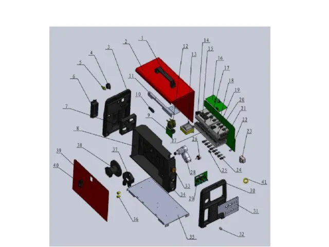
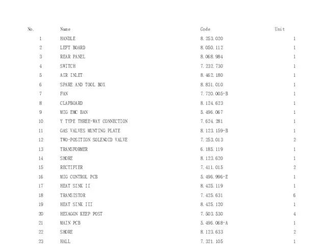
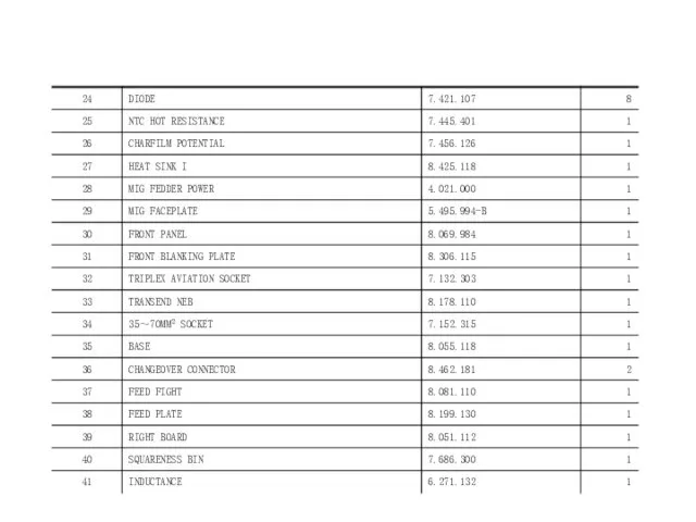
- 32. List of spare part
- 34. Скачать презентацию
Catalogue
1、Introduction of working principle
2、Introduction of main circuit(parts different from MMA)
3、Introduction of
Catalogue
1、Introduction of working principle
2、Introduction of main circuit(parts different from MMA)
3、Introduction of

1、Introduction of working principle
1、Introduction of working principle
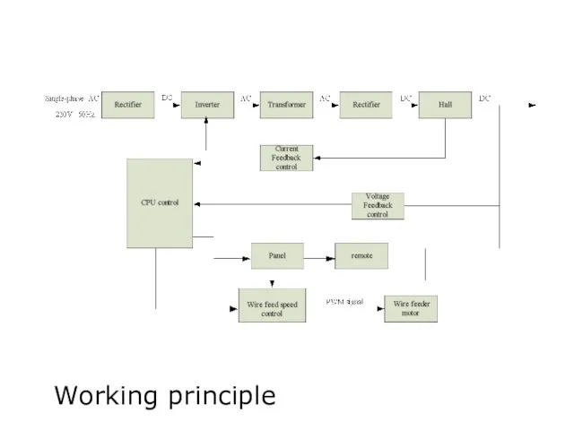
Working principle
Working principle
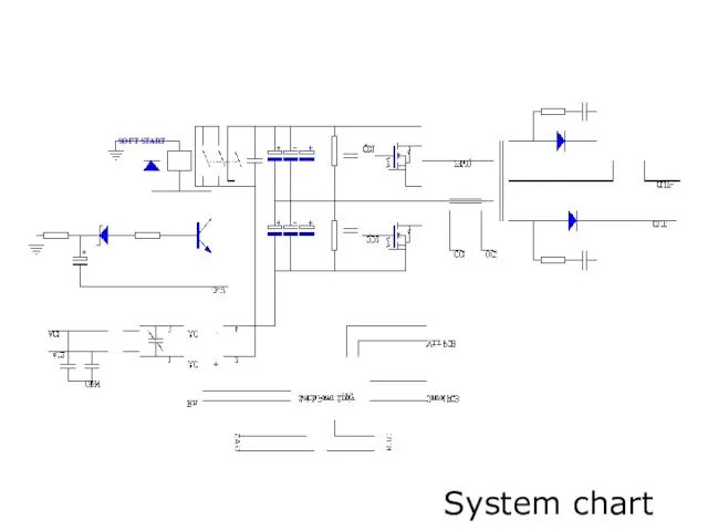
System chart
SOFT START
System chart
SOFT START
2、Introduction of main circuit(parts different from MMA)
2、Introduction of main circuit(parts different from MMA)
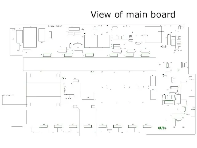
View of main board
View of main board
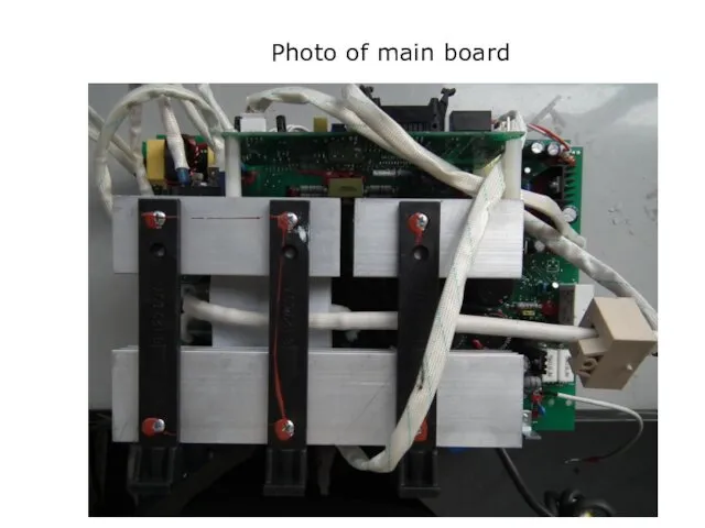
Photo of main board
Photo of main board
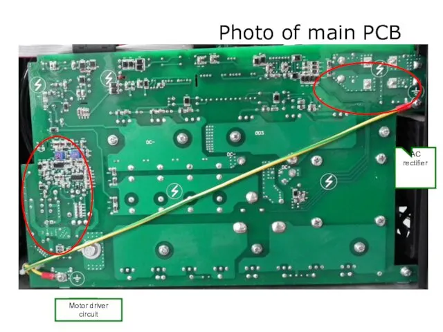
Photo of main PCB
AC rectifier
Motor driver circuit
Photo of main PCB
AC rectifier
Motor driver circuit
3、Introduction of control circuit(parts different from MMA)
3、Introduction of control circuit(parts different from MMA)
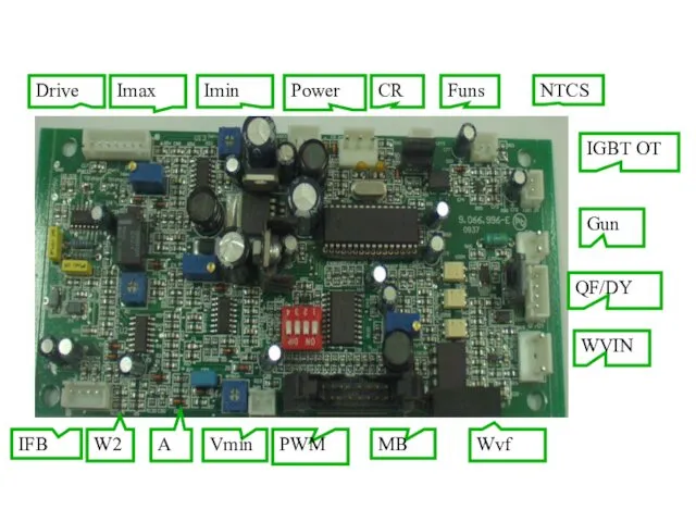
WVIN
IGBT OT
Gun
QF/DY
Drive
Power
CR
NTCS
Funs
IFB
PWM
MB
Imax
Imin
W2
A
Vmin
Wvf
WVIN
IGBT OT
Gun
QF/DY
Drive
Power
CR
NTCS
Funs
IFB
PWM
MB
Imax
Imin
W2
A
Vmin
Wvf
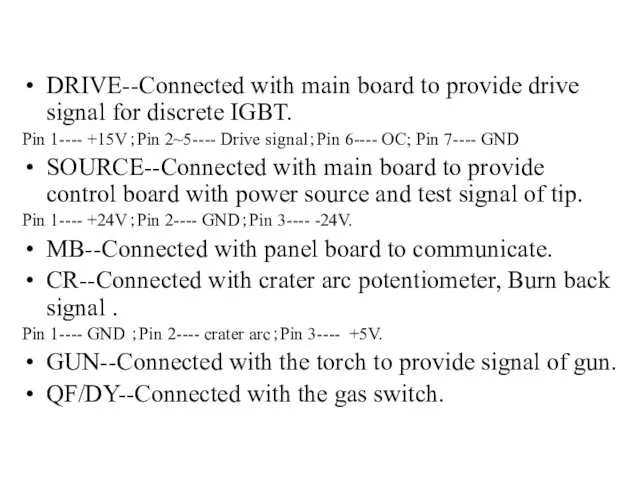
DRIVE--Connected with main board to provide drive signal for discrete IGBT.
Pin
DRIVE--Connected with main board to provide drive signal for discrete IGBT.
Pin
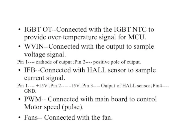
IGBT OT--Connected with the IGBT NTC to provide over-temperature signal for
IGBT OT--Connected with the IGBT NTC to provide over-temperature signal for
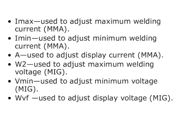
Imax—used to adjust maximum welding current (MMA).
Imin—used to adjust minimum welding
Imax—used to adjust maximum welding current (MMA).
Imin—used to adjust minimum welding
4、Introduction of panel circuit
4、Introduction of panel circuit
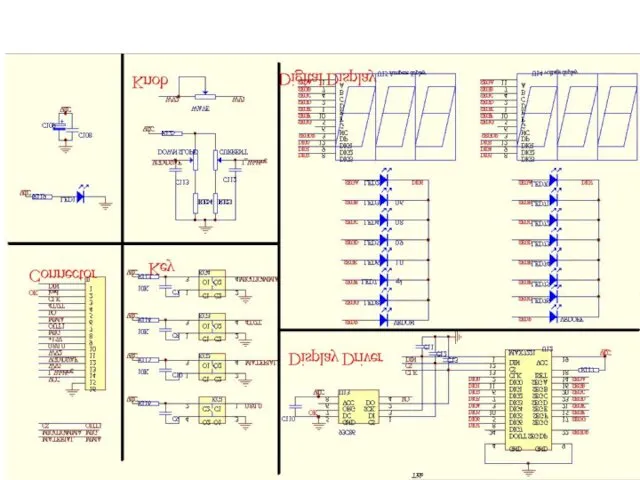
Electrical drawing of panel board
Electrical drawing of panel board
View of panel board
View of panel board
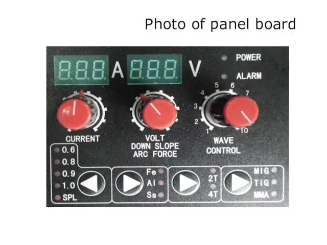
Photo of panel board
Photo of panel board
5、Troubleshooting
Series A: Troubles about panel display
Series B: Troubles about power
5、Troubleshooting
Series A: Troubles about panel display
Series B: Troubles about power
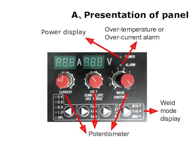
A、Presentation of panel
Power display
Over-temperature or Over-current alarm
Potentiometer
Weld mode display
A、Presentation of panel
Power display
Over-temperature or Over-current alarm
Potentiometer
Weld mode display
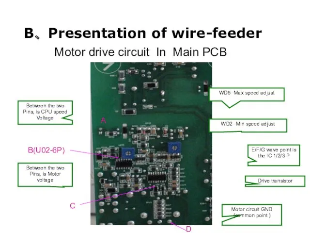
Motor drive circuit In Main PCB
WD5--Max speed adjust
WD2--Min speed adjust
Between
Motor drive circuit In Main PCB
WD5--Max speed adjust
WD2--Min speed adjust
Between
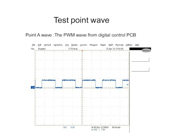
Test point wave
Point A wave :The PWM wave from digital control
Test point wave
Point A wave :The PWM wave from digital control
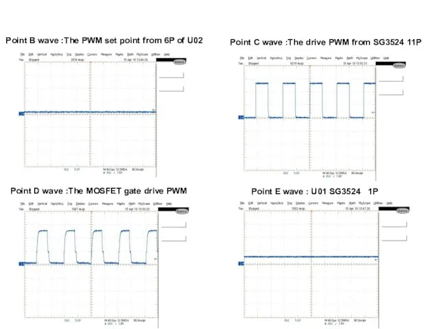
Point B wave :The PWM set point from 6P of U02
Point B wave :The PWM set point from 6P of U02
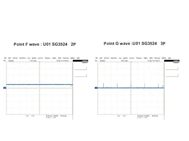
Point F wave : U01 SG3524 2P
Point G wave :U01 SG3524
Point F wave : U01 SG3524 2P
Point G wave :U01 SG3524
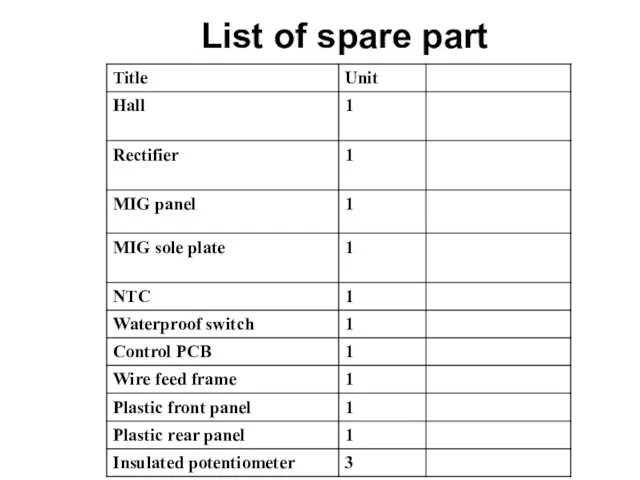
List of spare part
List of spare part
 Конспект образовательной деятельности по экологии в средней группе с использованием ИКТ на тему: Берегите лес
 Основные характеристики центрального процессора
 методическое пособие
 Теоретические основы органической химии
 немного обо мне
 Автоматизация звука Ч в словах, предложениях.
 Презентация Панорама классного часа.
 Перинатальная патология центральной нервной системы
 Синегнойная палочка (Pseudomonas aeruginosa)
 Навигационное планирование и подготовка судна к переходу по маршруту
 Балалар ертегілері
 Моя будущая профессия: Стоматолог
 Представление о семье!!!
 Базовые понятия языка Си
 Знаменитые люди поселка Вырица. Иван Антонович Ефремов
 Презентация 1
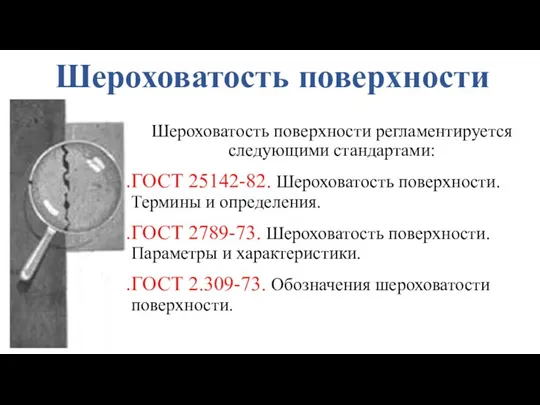 Шероховатость поверхности
 Система финансирования дополнительных занятий
 Любимый мой Башкортостан
 проект Солнышко в технике изонити
 Моя мама учитель. презентация
 Физиология нейрона, нервного волокна и синапса
 Кроссворд на тему Отечественная война 1812 года
 класс. ЛР №5
 Конденсационная установка
 Презентация Весёлая гимнастика для язычка часть2
 XIX Всемирный фестиваль молодёжи и студентов
 Сегментирование и позиционирование