- PCB Recycling Component Level Repair Techniques

Содержание
- 2. Adjustments Procedure I. Item preparation: 1. Input a white signal. (please refer to the next slide
- 3. 1. External pattern generator. 2. Internal white pattern in Service mode. (Please see next slide on
- 4. White Red Green Blue ON/OFF Aging Ramp Red Ramp Green Ramp Blue 1% window Color bar
- 5. II. Driver Adjustment TH42PX60 Adjustment voltage
- 6. III. Initialization Pulse Adjustment Input a White signal into the unit. Set picture controls as follows:
- 7. Adjustment necessary when PC board exchanged Adjust the following voltages using a multimeter: Caution: Do not
- 8. Common symptoms experienced if the adjustment is not performed Several images maybe displayed at the same
- 9. POWER SUPPLY
- 10. Sequence of events when Plasma TV is plugged in When a Plasma TV is plugged in,
- 11. Standby Block (Part1)
- 12. Standby Block (Part2)
- 13. Power Supply (Standby Circuit)
- 14. STB 5V Distribution
- 15. Power Supply (Standby Circuit)
- 16. STB5V, STB3.3V & STB1.5V P
- 17. F-STB-ON (Primary) P
- 18. F-STB-14V P
- 19. STB5V and TV-SUB-ON function on PA board PA
- 20. SUB-Voltages Output from the PA board
- 21. PA Board Test Points
- 22. POWER ON
- 23. POWER ON
- 24. Panel Standby ON Circuit 3.3v
- 25. Power Supply Secondary Circuit
- 26. VSUS and VDA Circuit
- 27. PA Board Circuit Explanation
- 28. Main voltages output from the PA Circuit
- 29. 5V Distribution
- 30. VSUS Distribution
- 31. Troubleshooting Guide Can the click sound from the relay be Heard after the TV is plugged
- 33. Скачать презентацию
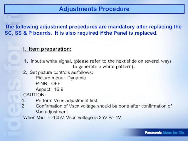
Adjustments Procedure
I. Item preparation:
1. Input a white signal. (please refer to
Adjustments Procedure
I. Item preparation:
1. Input a white signal. (please refer to
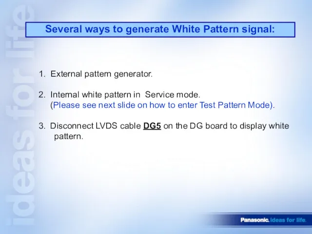
1. External pattern generator.
2. Internal white pattern in Service mode.
(Please
1. External pattern generator.
2. Internal white pattern in Service mode.
(Please
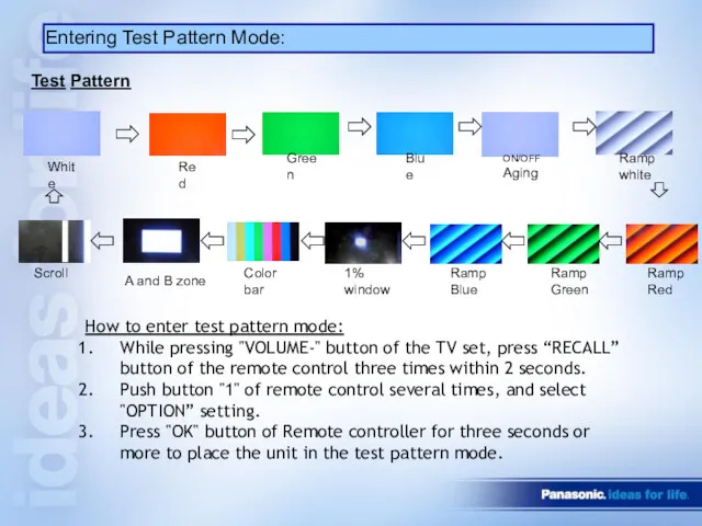
White
Red
Green
Blue
ON/OFF Aging
Ramp Red
Ramp Green
Ramp Blue
1% window
Color bar
A and B zone
Scroll
Ramp white
Test
White
Red
Green
Blue
ON/OFF Aging
Ramp Red
Ramp Green
Ramp Blue
1% window
Color bar
A and B zone
Scroll
Ramp white
Test
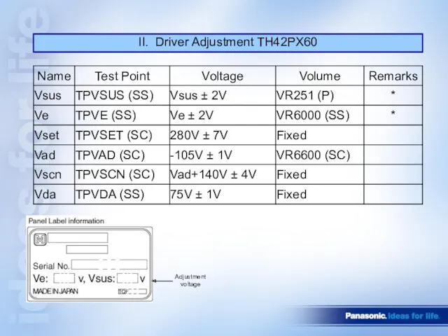
II. Driver Adjustment TH42PX60
Adjustment voltage
II. Driver Adjustment TH42PX60
Adjustment voltage
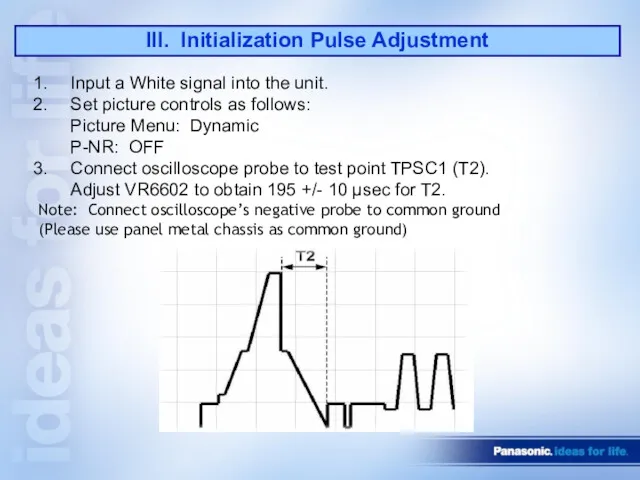
III. Initialization Pulse Adjustment
Input a White signal into the unit.
Set picture
III. Initialization Pulse Adjustment
Input a White signal into the unit.
Set picture
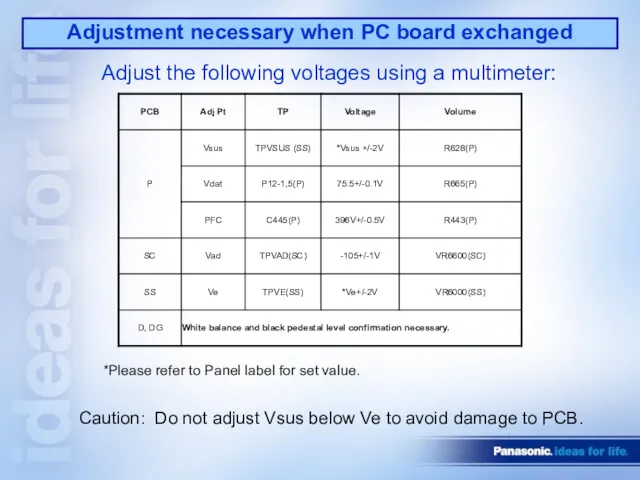
Adjustment necessary when PC board exchanged
Adjust the following voltages using a
Adjustment necessary when PC board exchanged
Adjust the following voltages using a
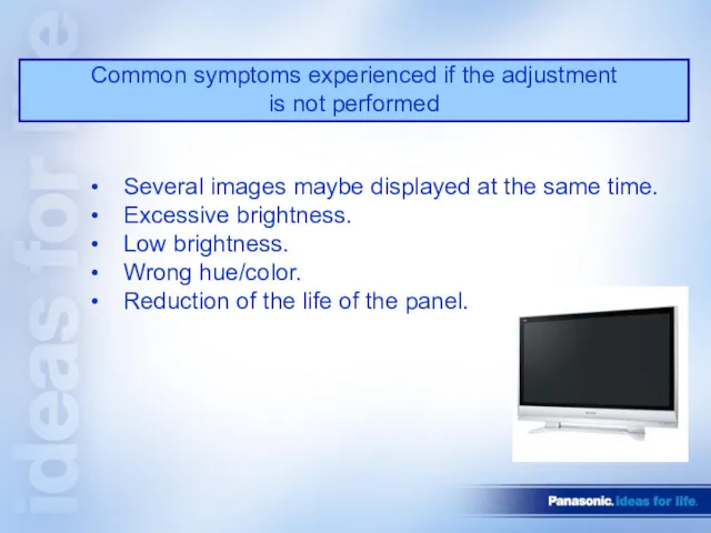
Common symptoms experienced if the adjustment
is not performed
Several images maybe
Common symptoms experienced if the adjustment
is not performed
Several images maybe
POWER SUPPLY
POWER SUPPLY
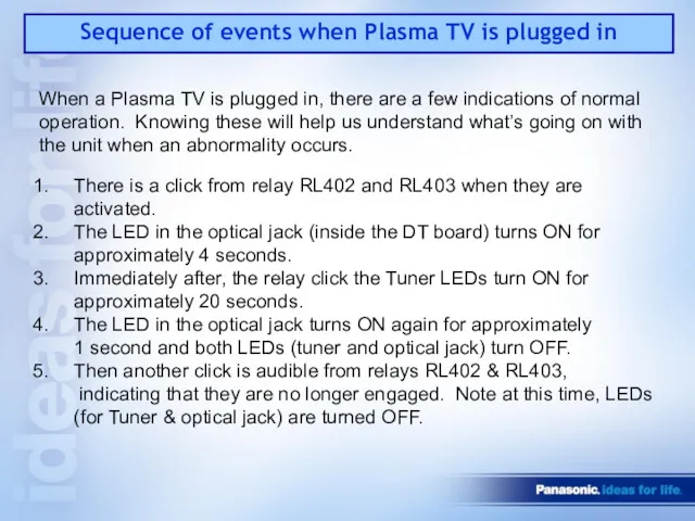
Sequence of events when Plasma TV is plugged in
When a Plasma
Sequence of events when Plasma TV is plugged in
When a Plasma
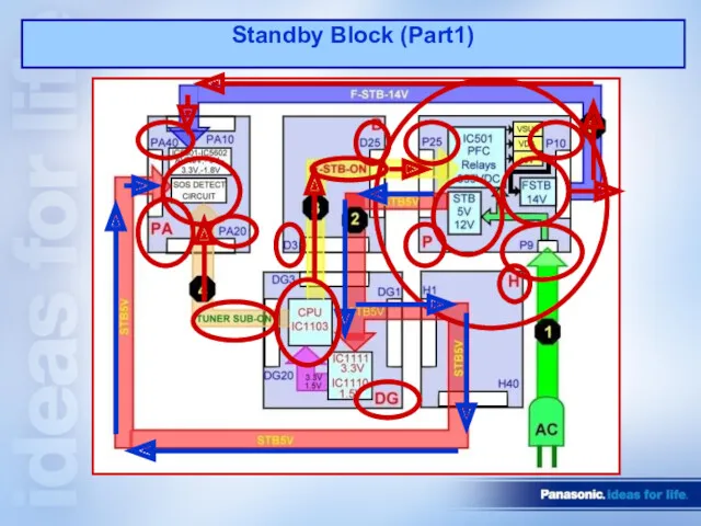
Standby Block (Part1)
Standby Block (Part1)
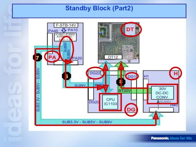
Standby Block (Part2)
Standby Block (Part2)
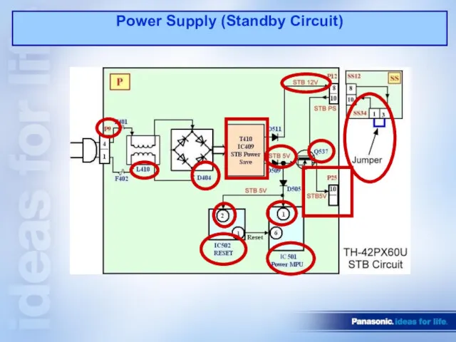
Power Supply (Standby Circuit)
Power Supply (Standby Circuit)
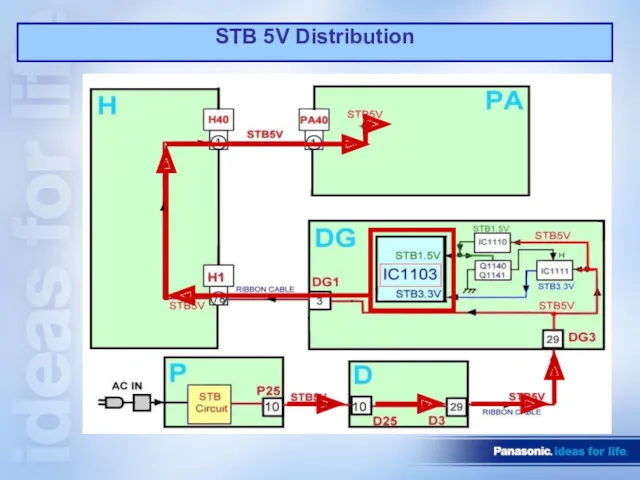
STB 5V Distribution
STB 5V Distribution
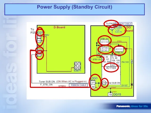
Power Supply (Standby Circuit)
Power Supply (Standby Circuit)
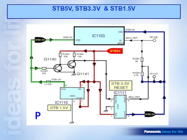
STB5V, STB3.3V & STB1.5V
P
STB5V, STB3.3V & STB1.5V
P
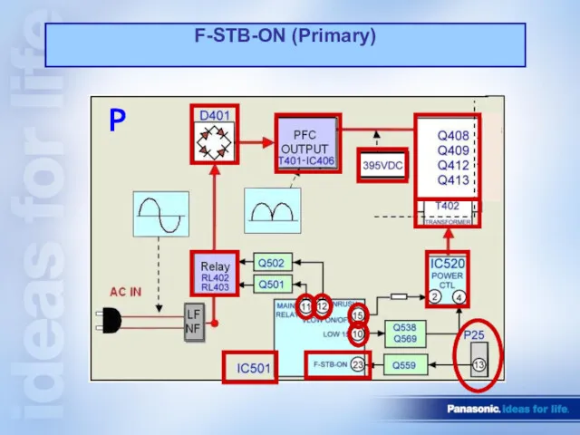
F-STB-ON (Primary)
P
F-STB-ON (Primary)
P
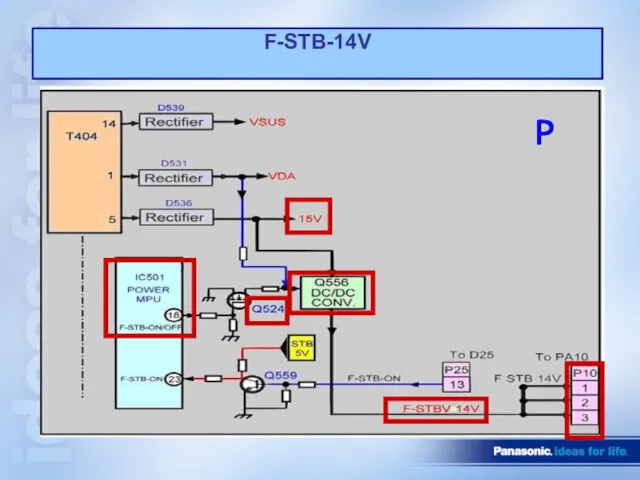
F-STB-14V
P
F-STB-14V
P

STB5V and TV-SUB-ON function on PA board
PA
STB5V and TV-SUB-ON function on PA board
PA
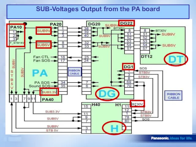
SUB-Voltages Output from the PA board
SUB-Voltages Output from the PA board
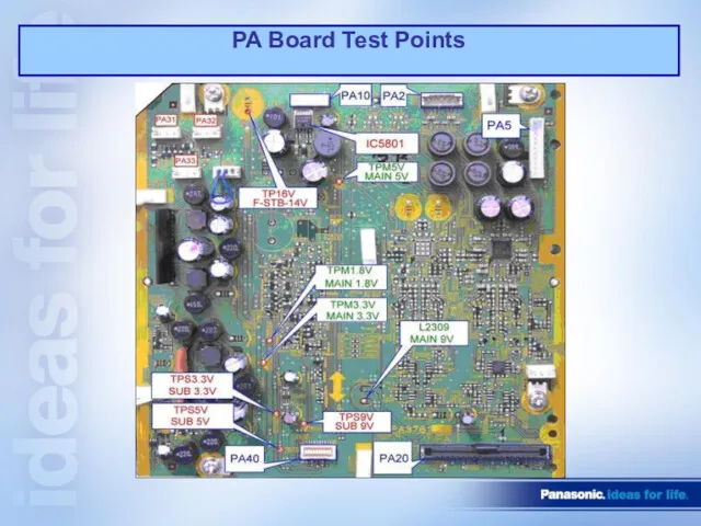
PA Board Test Points
PA Board Test Points
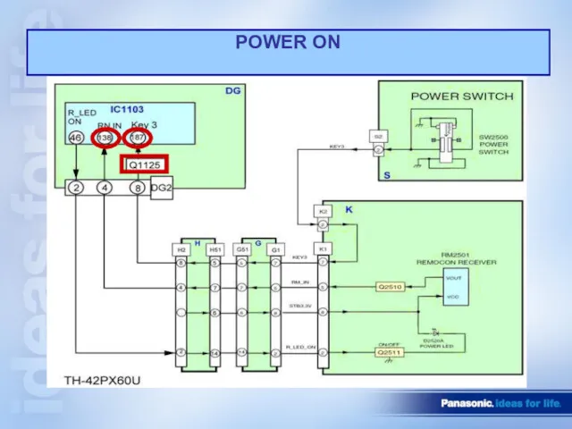
POWER ON
POWER ON
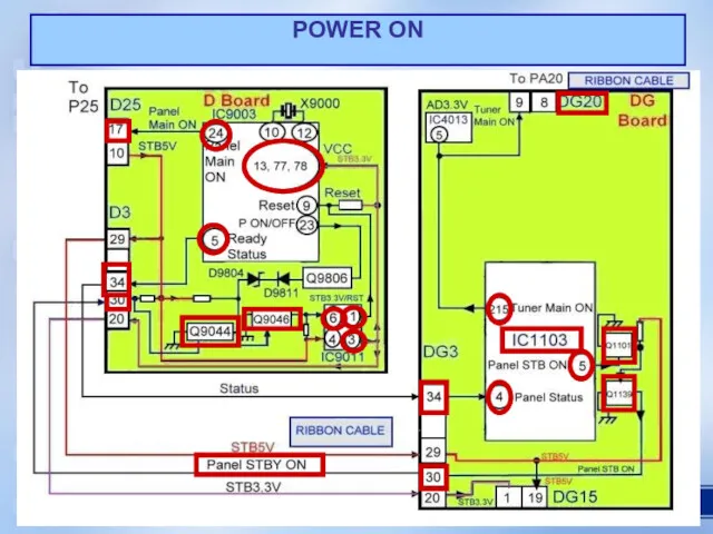
POWER ON
POWER ON
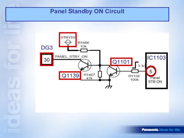
Panel Standby ON Circuit
3.3v
Panel Standby ON Circuit
3.3v
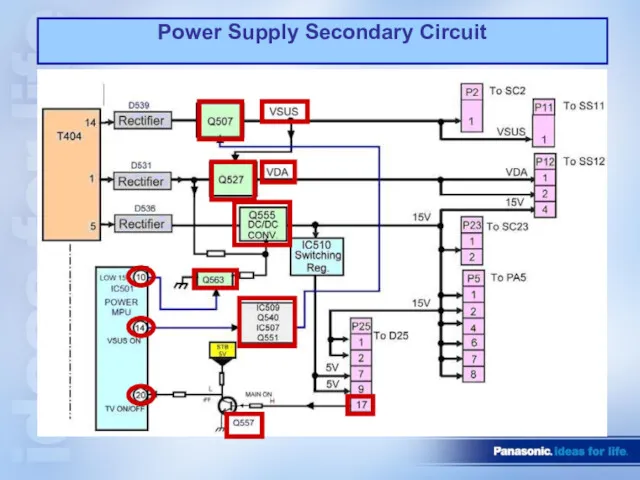
Power Supply Secondary Circuit
Power Supply Secondary Circuit
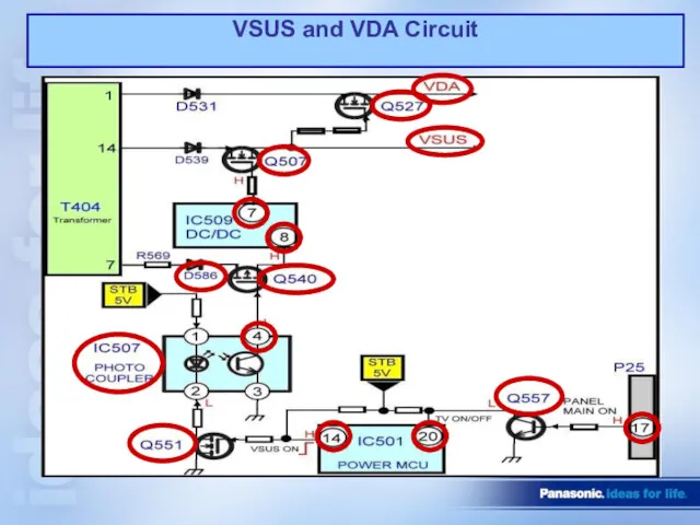
VSUS and VDA Circuit
VSUS and VDA Circuit
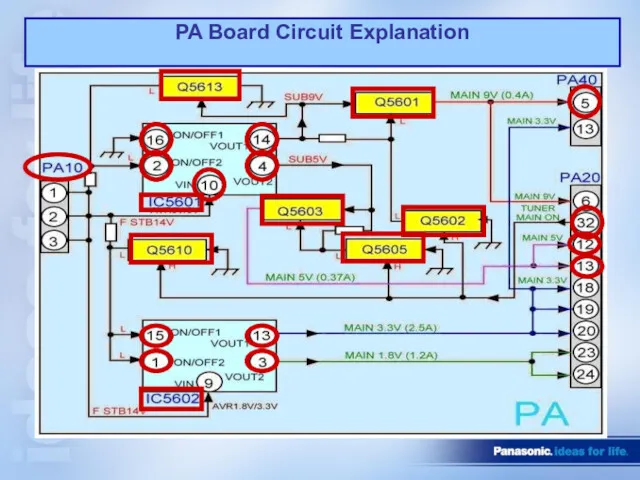
PA Board Circuit Explanation
PA Board Circuit Explanation
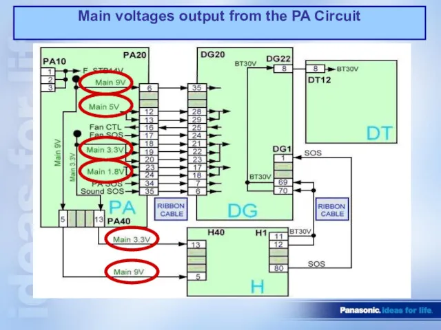
Main voltages output from the PA Circuit
Main voltages output from the PA Circuit
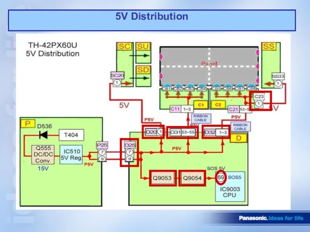
5V Distribution
5V Distribution
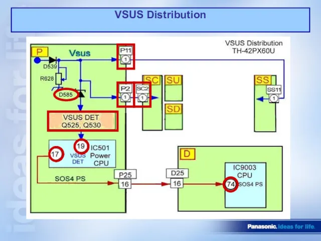
VSUS Distribution
VSUS Distribution
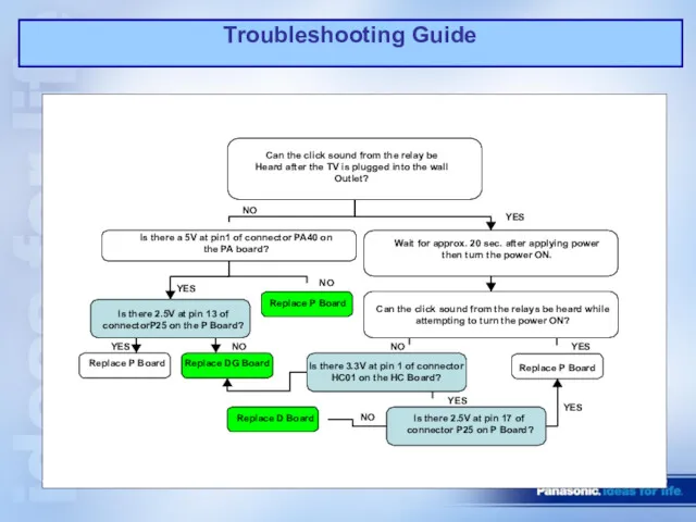
Troubleshooting Guide
Can the click sound from the relay be
Heard after the
Troubleshooting Guide
Can the click sound from the relay be
Heard after the
 IT – Скорая. Организация по ремонту компьютеров
 Основной курс: урок 27
 Взаимоотношения внутри популяции
 Личность. Развитие личности: самосознание, самооценка
 Туристские возможности родного края
 Организация высшего образования в РФ. Лицензирование, аккредитация и аттестация вузов. Государственные образовательные стандарты
 Безопасность на дороге
 Психология человека
 Керування проектами
 Внутреннее убранство русской избы
 Механизация поверхностной обработки почвы при возделывании озимой пшеницы
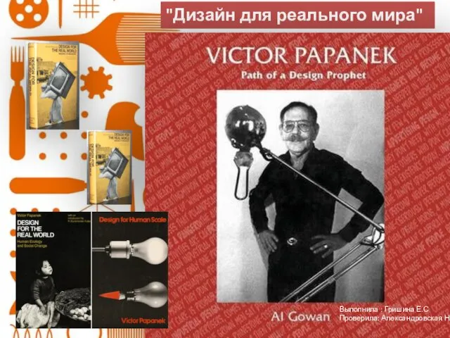 Дизайн для реального мира. Виктор Папанек (1923-1980)
 Презентация к уроку Птичьи разговоры
 Религиозный этикет в праздниках. Никах
 Дидактические игры по развитию речи
 Подобные треугольники
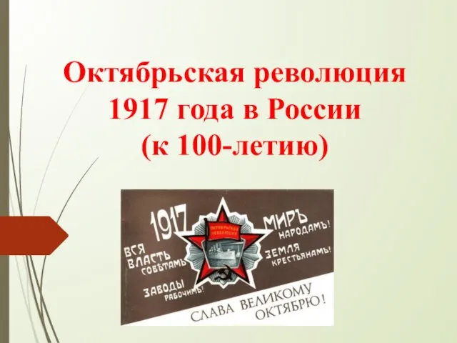 Октябрьская революция 1917 года в России
 Единицы объёма. Решение задач на нахождение объёма
 Самопрезентация
 Значение разминки в физической культуре
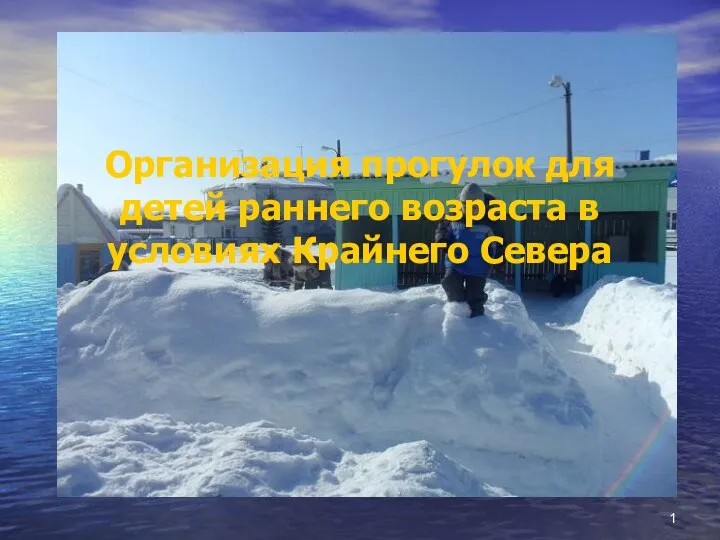 Организация прогулок для детей раннего возраста в условиях Крайнего Севера
 Алжи́рская Наро́дная Демократи́ческая Республика
 презентация Великой Победе посвящается
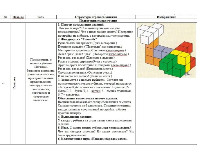 Перспективное планирование работы с Логическими кубиками для всех Б.П.Никтина подготовительная группа
 Место СМИ во взаимодействии власти и общества
 Игра по ПДД На улицах и дорогах
 Авиационный транспорт Украины
 Москва и ее жители в ХVI веке