- Steel DC TIG welding training material. Version 1.0

Содержание
- 2. DC TIG welding
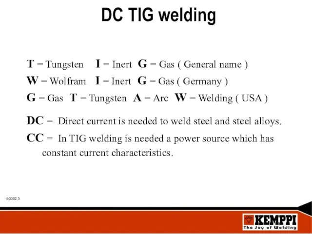
- 3. DC TIG welding T = Tungsten I = Inert G = Gas ( General name )
- 4. TIG benefits and features • Good visibility to the weld pool, no smoke or welding slag.
- 5. TIG process limitations Lower productivity than in MIG / MAG welding. Sensitive for base or filler
- 6. TIG applications TIG is suitable in steel welding cases where quality and visual appearance of weld
- 7. Constant current ( CC ):
- 8. DC TIG polarity On steel TIG welding is used DC current, electrode connected to -pole (
- 9. High frequency ignition ( HF ) In steel welding DC TIG arc is recommended to ignite
- 10. Contact ignition DC TIG arc can also be ignited by contacting with tungsten electrode to the
- 11. Welding preparations Steel is having normally on it´s surface slag coming from the material hot rolling
- 12. Torch angle In welding without filler wire TIG torch angle is 75º - 80º Welding wire
- 13. Filler wires In TIG - welding is minimum number of alloy loses, because filler wire is
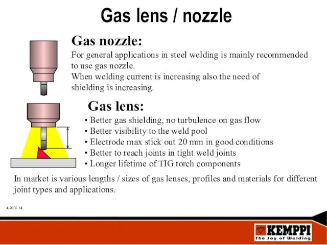
- 14. Gas lens: Better gas shielding, no turbulence on gas flow Better visibility to the weld pool
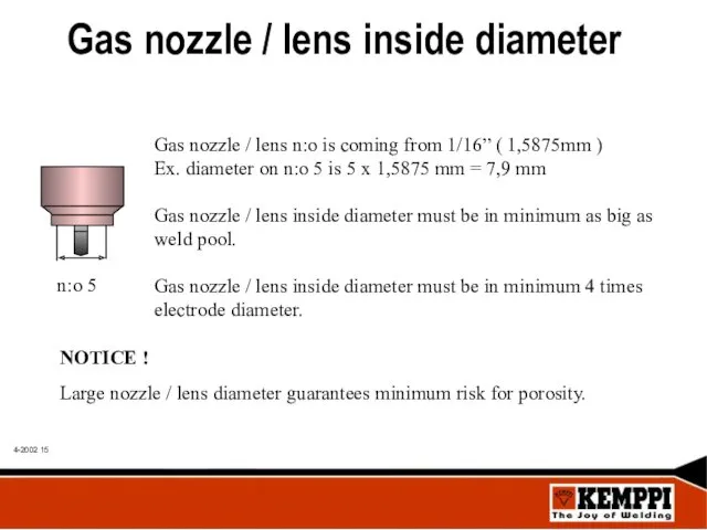
- 15. Gas nozzle / lens inside diameter Gas nozzle / lens n:o is coming from 1/16” (
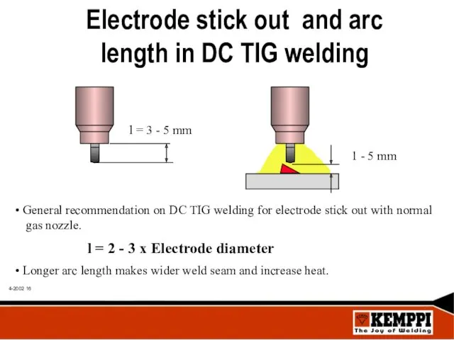
- 16. Electrode stick out and arc length in DC TIG welding General recommendation on DC TIG welding
- 17. Arc length depends on used current and joint type as follows: Fillet joints collect gas, electrode
- 18. Steel DC TIG gas flow Flow of shielding gas is depending lot of welding conditions: Inside
- 19. Electrode diameter selection Electrode Gas nozzle Gas Current diameter no: flow range 1,6 mm 4 -
- 20. Tungsten electrodes CODE ALLOY COLOUR CODE USE WP 100% W Green ( AC ) WC 20
- 21. Electrode sharpening L = 1...5 x d d = 2,4 mm L = 5 x 2,4
- 22. Electrode diameter / welding current TIG electrode diameter / max welding current ( DC ): 0,8
- 23. Steel TIG shielding gases GAS USE Argon + 0,03% NO General use Argon 99,99% General use
- 24. Root protection For general applications most of the steel pipes are TIG welded without shielding in
- 25. Root gas on pipe welding Best root protection is shielding gas. Flush shielding space with shielding
- 26. Removable root backing bar On steel welding backing bar is normally manufactured from copper. Avoid situation
- 27. Copper backing bars Backing bar groove depth should be according to plate thickness. Too shallow groove
- 28. Benefits and task of backing bars Protect root side against oxidisation • Support and forms a
- 29. Pre gas / Post flow functions During Pre gas function shielding gas is flowing to the
- 30. Up / Down slope functions During Up slope time welding current is raising from ignition level
- 31. Steel joint forms
- 32. Heat input Heat what arc is bringing to base material is called Heat input ( Q
- 33. Thermal efficiency Calculate total heat input ( Q ) by using thermal efficiency correction factor (
- 34. Average current In case that machine is not having automatic function to calculate average current on
- 35. TIG treatment TIG treatment is used in cases where MIG / MAG seam needs: improve dynamically
- 36. Steel Pulsed TIG welding In Pulsed TIG welding current changes according set frequency between higher pulse
- 37. Pulse parameters regulation variants Various pulse profiles can give same average current but different welding speed
- 38. Rapid pulse ( RP ) Pulsed TIG welding is divided to two main section: Frequency from
- 39. Long pulse ( LP ) From 5 to 0,1 Hz ( 0,2 s - 10 s
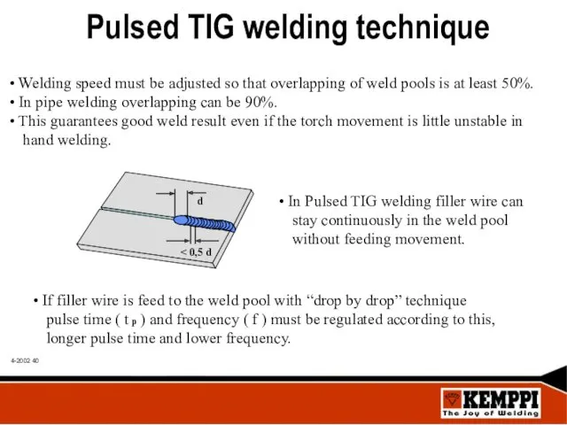
- 40. Pulsed TIG welding technique Welding speed must be adjusted so that overlapping of weld pools is
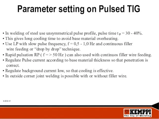
- 41. Parameter setting on Pulsed TIG In welding of steel use unsymmetrical pulse profile, pulse time t
- 42. With Multisystem PS / PSS + TU equipment use C 100 P remote pulse unit. Kemppi`s
- 43. Pulsed DC TIG welding applications Pulsed DC TIG welding is a flexible welding process for all
- 44. TIG Minilog function With Minilog function welder can select between two pre-set current levels from the
- 45. TIG Minilog benefits To avoid welding faults at starts Better weld pool control in positional welding
- 46. TIG Minilog applications Pre heat of base material before welding Starting from thin material or from
- 47. TIG Spot welding of steel Press TIG torch against welded plates TIG Spot welding is done
- 48. Weld data: Steel
- 50. Скачать презентацию
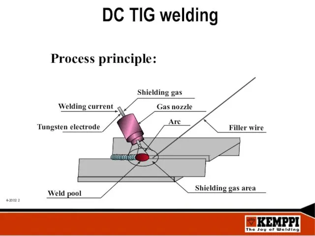
DC TIG welding
DC TIG welding
DC TIG welding
T = Tungsten I = Inert G = Gas
DC TIG welding
T = Tungsten I = Inert G = Gas
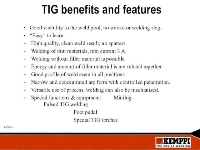
TIG benefits and features
• Good visibility to the weld pool, no
TIG benefits and features
• Good visibility to the weld pool, no
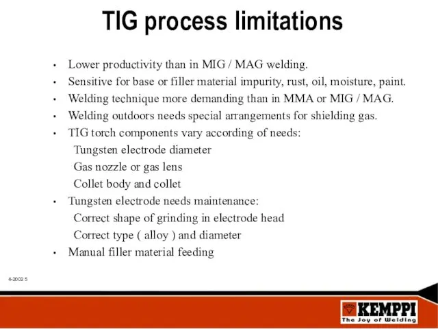
TIG process limitations
Lower productivity than in MIG / MAG welding.
Sensitive for
TIG process limitations
Lower productivity than in MIG / MAG welding.
Sensitive for
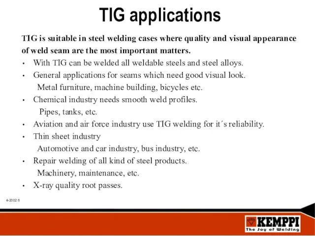
TIG applications
TIG is suitable in steel welding cases where quality and
TIG applications
TIG is suitable in steel welding cases where quality and
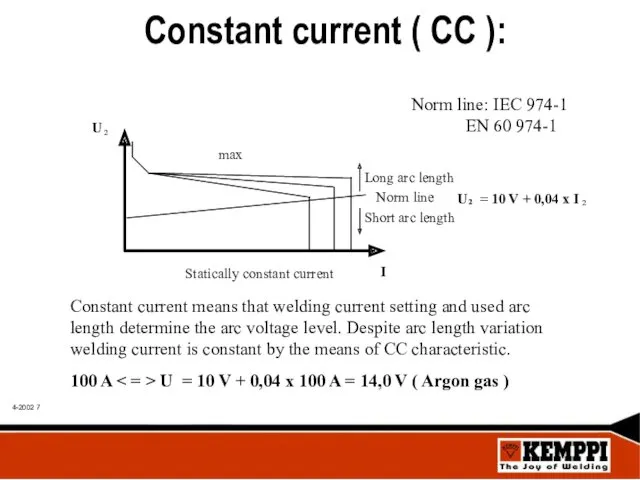
Constant current ( CC ):
Constant current ( CC ):
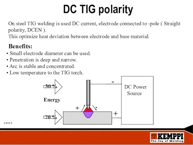
DC TIG polarity
On steel TIG welding is used DC current, electrode
DC TIG polarity
On steel TIG welding is used DC current, electrode
High frequency ignition ( HF )
In steel welding DC TIG
High frequency ignition ( HF )
In steel welding DC TIG
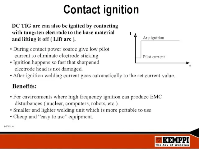
Contact ignition
DC TIG arc can also be ignited by contacting
with
Contact ignition
DC TIG arc can also be ignited by contacting
with
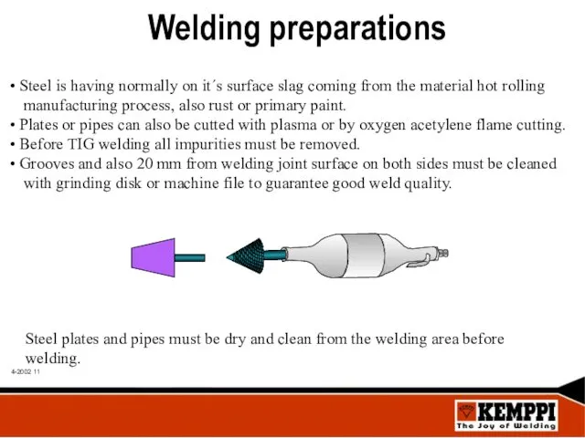
Welding preparations
Steel is having normally on it´s surface slag coming
Welding preparations
Steel is having normally on it´s surface slag coming
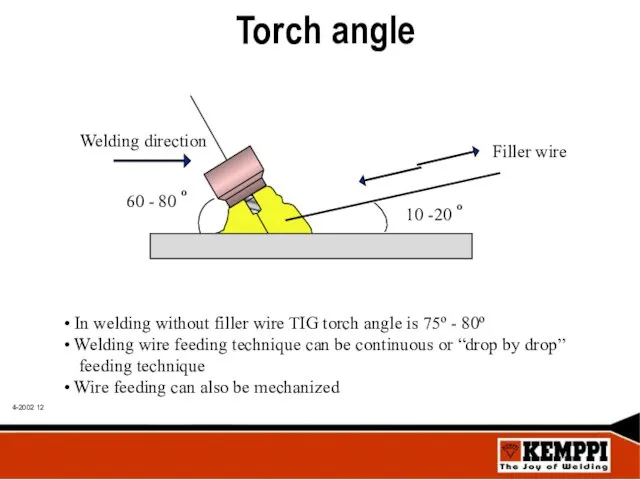
Torch angle
In welding without filler wire TIG torch angle is
Torch angle
In welding without filler wire TIG torch angle is
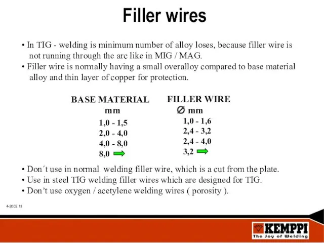
Filler wires
In TIG - welding is minimum number of alloy
Filler wires
In TIG - welding is minimum number of alloy
Gas lens:
Better gas shielding, no turbulence on gas flow
Gas lens:
Better gas shielding, no turbulence on gas flow
Gas nozzle / lens inside diameter
Gas nozzle / lens n:o is
Gas nozzle / lens inside diameter
Gas nozzle / lens n:o is
Electrode stick out and arc length in DC TIG welding
General
Electrode stick out and arc length in DC TIG welding
General
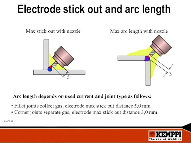
Arc length depends on used current and joint type as follows:
Arc length depends on used current and joint type as follows:
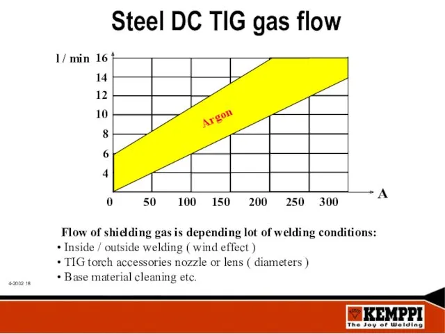
Steel DC TIG gas flow
Flow of shielding gas is depending lot
Steel DC TIG gas flow
Flow of shielding gas is depending lot
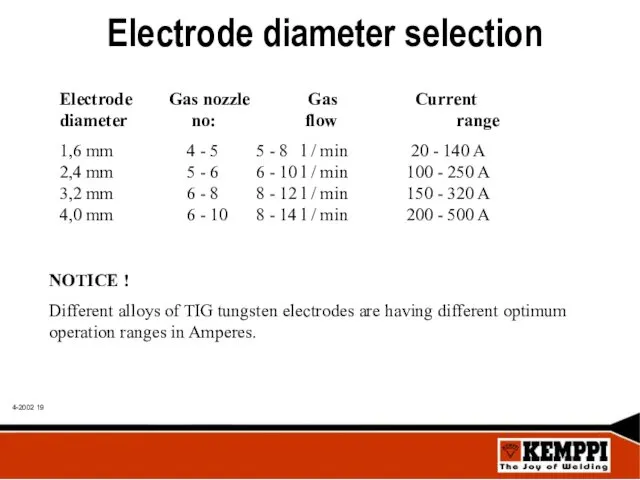
Electrode diameter selection
Electrode Gas nozzle Gas Current
diameter no: flow range
1,6
Electrode diameter selection
Electrode Gas nozzle Gas Current
diameter no: flow range
1,6
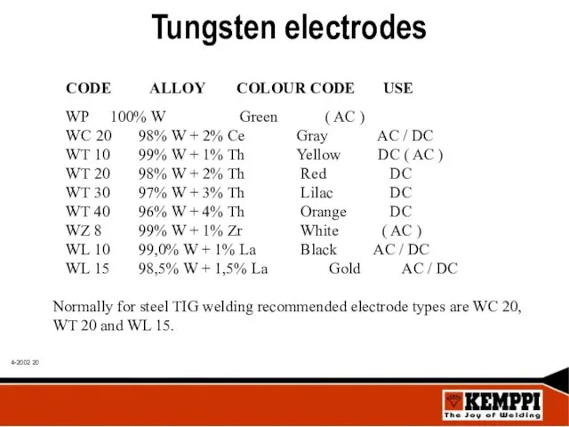
Tungsten electrodes
CODE ALLOY COLOUR CODE USE
WP 100% W Green ( AC )
WC
Tungsten electrodes
CODE ALLOY COLOUR CODE USE
WP 100% W Green ( AC )
WC
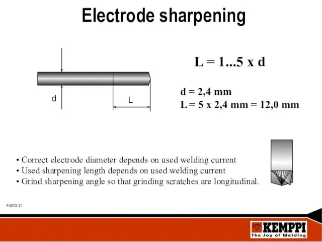
Electrode sharpening
L = 1...5 x d
d = 2,4 mm
L =
Electrode sharpening
L = 1...5 x d
d = 2,4 mm
L =
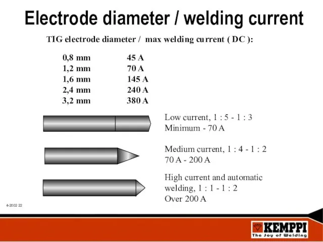
Electrode diameter / welding current
TIG electrode diameter / max welding
Electrode diameter / welding current
TIG electrode diameter / max welding
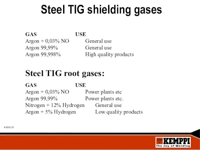
Steel TIG shielding gases
GAS USE
Argon + 0,03% NO General use
Argon 99,99% General use
Argon
Steel TIG shielding gases
GAS USE
Argon + 0,03% NO General use
Argon 99,99% General use
Argon
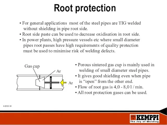
Root protection
For general applications most of the steel pipes are
Root protection
For general applications most of the steel pipes are
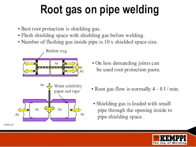
Root gas on pipe welding
Best root protection is shielding gas.
Root gas on pipe welding
Best root protection is shielding gas.
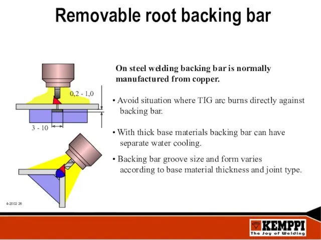
Removable root backing bar
On steel welding backing bar is normally
manufactured
Removable root backing bar
On steel welding backing bar is normally
manufactured
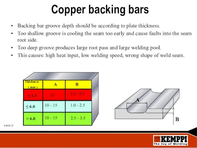
Copper backing bars
Backing bar groove depth should be according to plate
Copper backing bars
Backing bar groove depth should be according to plate
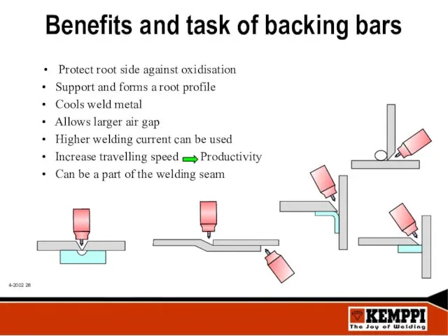
Benefits and task of backing bars
Protect root side against oxidisation
• Support
Benefits and task of backing bars
Protect root side against oxidisation
• Support
Pre gas / Post flow functions
During Pre gas function shielding
Pre gas / Post flow functions
During Pre gas function shielding
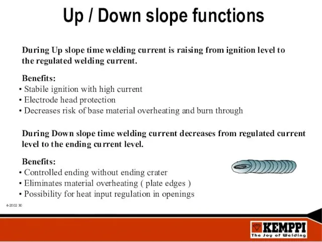
Up / Down slope functions
During Up slope time welding current is
Up / Down slope functions
During Up slope time welding current is
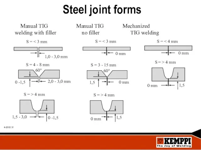
Steel joint forms
Steel joint forms
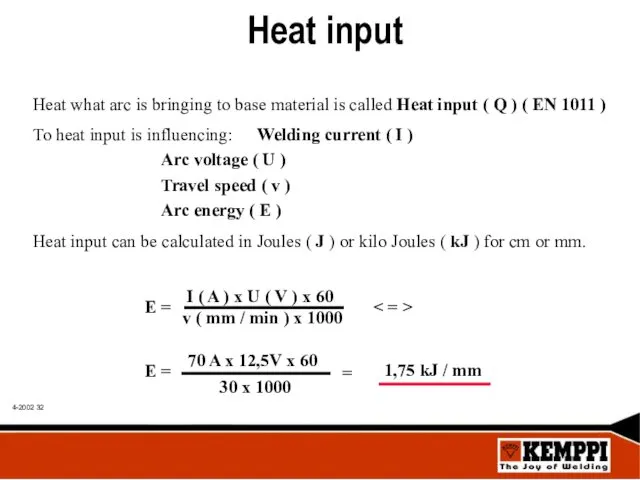
Heat input
Heat what arc is bringing to base material is called
Heat input
Heat what arc is bringing to base material is called
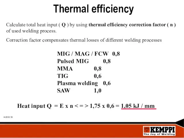
Thermal efficiency
Calculate total heat input ( Q ) by using
Thermal efficiency
Calculate total heat input ( Q ) by using
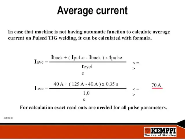
Average current
In case that machine is not having automatic function
Average current
In case that machine is not having automatic function
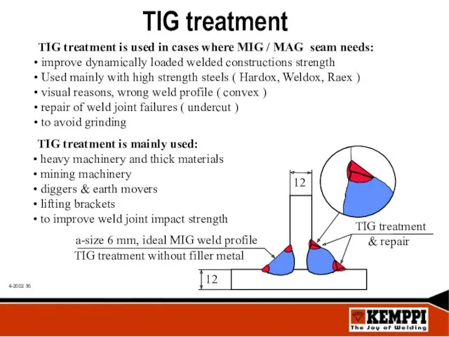
TIG treatment
TIG treatment is used in cases where MIG / MAG
TIG treatment
TIG treatment is used in cases where MIG / MAG
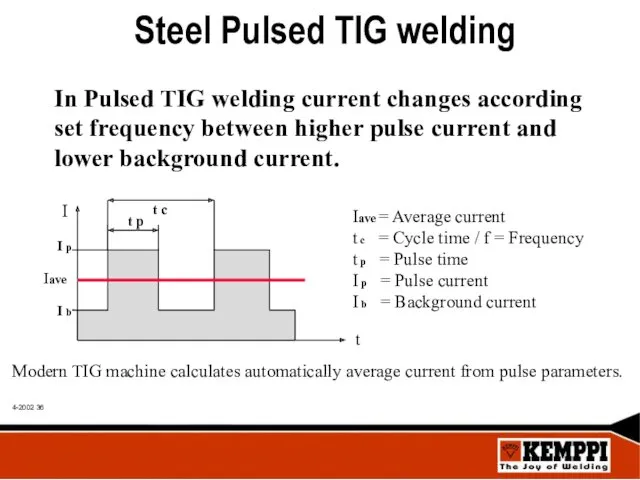
Steel Pulsed TIG welding
In Pulsed TIG welding current changes according
set
Steel Pulsed TIG welding
In Pulsed TIG welding current changes according
set
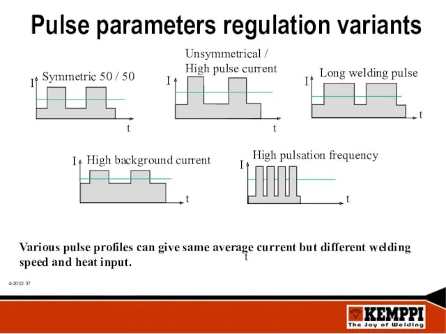
Pulse parameters regulation variants
Various pulse profiles can give same average current
Pulse parameters regulation variants
Various pulse profiles can give same average current
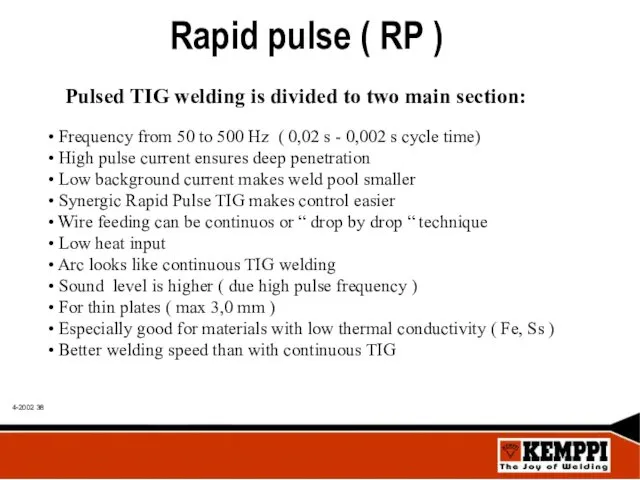
Rapid pulse ( RP )
Pulsed TIG welding is divided to two
Rapid pulse ( RP )
Pulsed TIG welding is divided to two
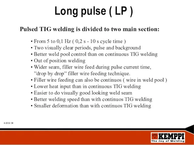
Long pulse ( LP )
From 5 to 0,1 Hz (
Long pulse ( LP )
From 5 to 0,1 Hz (
Pulsed TIG welding technique
Welding speed must be adjusted so that
Pulsed TIG welding technique
Welding speed must be adjusted so that
Parameter setting on Pulsed TIG
In welding of steel use unsymmetrical
Parameter setting on Pulsed TIG
In welding of steel use unsymmetrical
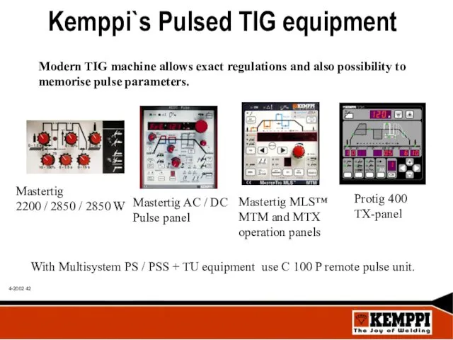
With Multisystem PS / PSS + TU equipment use C 100
With Multisystem PS / PSS + TU equipment use C 100
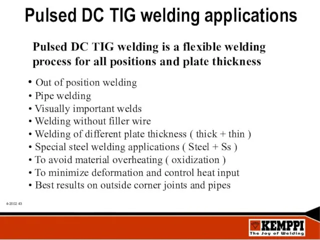
Pulsed DC TIG welding applications
Pulsed DC TIG welding is a flexible
Pulsed DC TIG welding applications
Pulsed DC TIG welding is a flexible
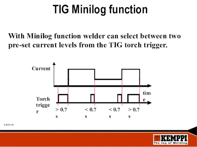
TIG Minilog function
With Minilog function welder can select between two pre-set
TIG Minilog function
With Minilog function welder can select between two pre-set
TIG Minilog benefits
To avoid welding faults at starts
Better weld
TIG Minilog benefits
To avoid welding faults at starts
Better weld
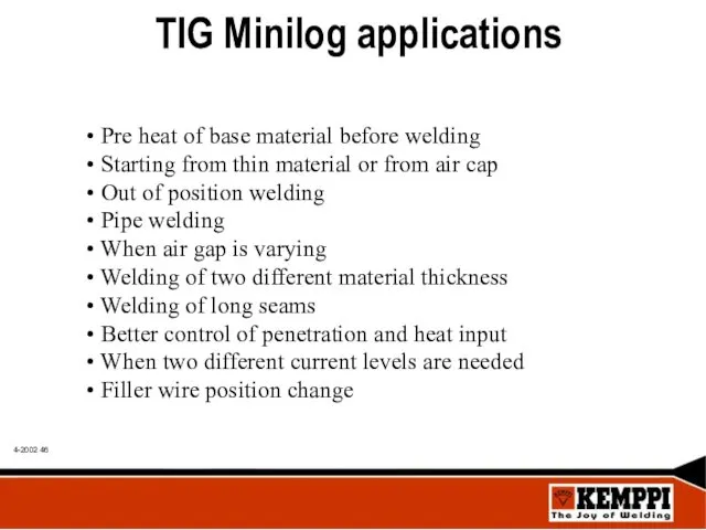
TIG Minilog applications
Pre heat of base material before welding
Starting
TIG Minilog applications
Pre heat of base material before welding
Starting
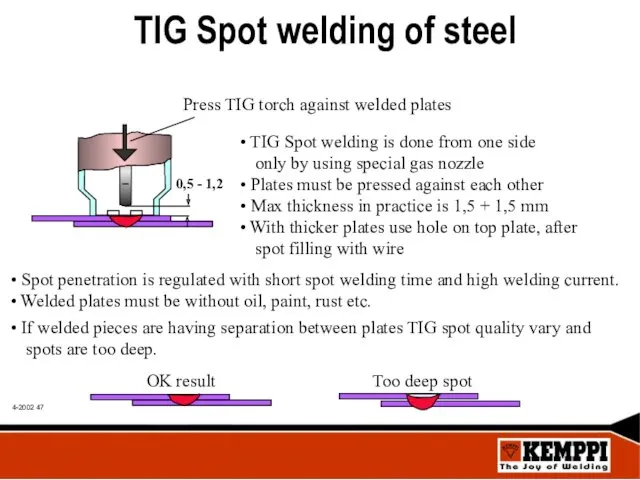
TIG Spot welding of steel
Press TIG torch against welded plates
TIG
TIG Spot welding of steel
Press TIG torch against welded plates
TIG
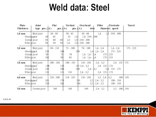
Weld data: Steel
Weld data: Steel
 Написание сочинения-рассуждения
 IVoice. Интеллектуальный голосовой помощник для вашего бизнеса
 Презентация к сценарию праздника Прощай, Букварь.
 Проектирование блочной котельной для гостиницы
 Путешествие в страну Морфемика. (5 класс)
 Ислам. Догматика ислама
 Применение подобия треугольников в жизни. Измерительные работы на местности
 Научно-исследовательская работа в группе Следопыт
 Цифровые данные. Цифровая технология. Цифровая революция
 Гипотезы возникновение жизни на Земле
 Кодирование и обработка графической информации
 Европейские нормативы теплозащиты зданий. Технологии теплозащиты и естественной вентиляции архитектурных сооружений в Казахстане
 Вода
Вода Маленькие герои большой войны. Кто такие пионеры?
 Таблица умножения для младших школьников (тренажер)
 Людовик ван Бетховен
 Моя театральная деятельность Диск
 Государства на политической карте мира
 Благоустройство объекта Свиридовский пруд
 Countable nouns
 Опиливание заготовок из сортового проката
 Органическая архитектура
 Уровень и качество жизни населения
 Виды треугольников. Логическая задача
 Затратный подход к оценке собственности
 Презентация Играем вместе
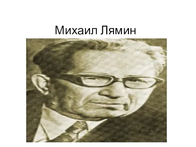 Михаил Лямин
 Как стать личностью