- Welding process

Содержание
- 2. Purposes of this report: - to give an outline of welding processes Welding is a process
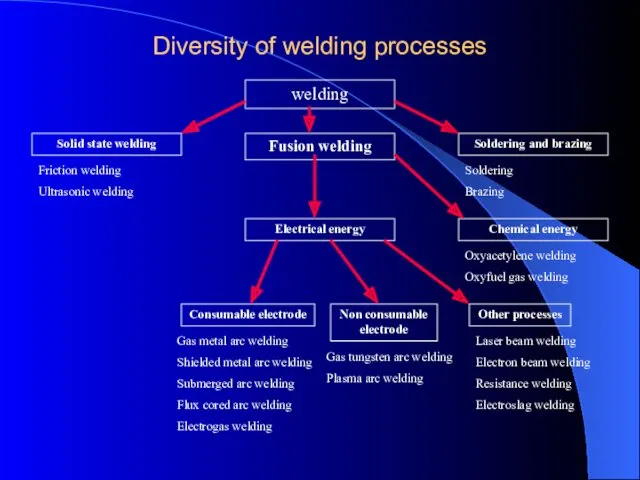
- 3. Diversity of welding processes welding Solid state welding Soldering and brazing Fusion welding Electrical energy Chemical
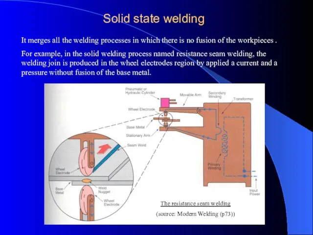
- 4. Solid state welding It merges all the welding processes in which there is no fusion of
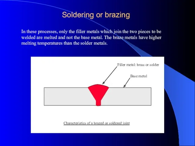
- 5. Soldering or brazing In these processes, only the filler metals which join the two pieces to
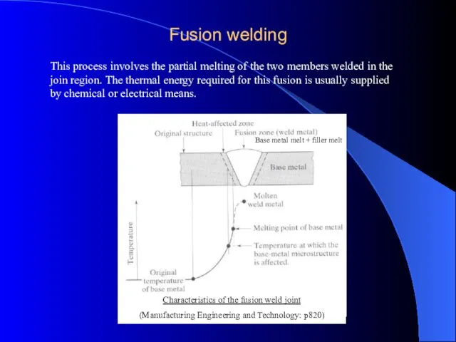
- 6. Fusion welding This process involves the partial melting of the two members welded in the join
- 7. Fusion welding Process
- 8. Topics to Discuss Introduction Oxyfuel Gas welding Arc-Welding Processes:Consumable electrode Electrodes Arc-Welding Processes:Non Consumable Process Thermit
- 9. Introduction Definition : Fusion Welding is defined as melting together and coalescing materials by means of
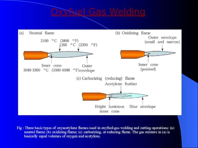
- 10. Oxyfuel Gas Welding Fig : Three basic types of oxyacetylene flames used in oxyfuel-gas welding and
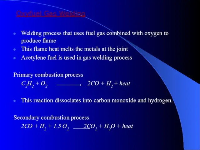
- 11. Oxyfuel Gas Welding Welding process that uses fuel gas combined with oxygen to produce flame This
- 12. Types of flames Neutral flame Oxidising flame Carburising flame Filler Metals : Additional material to weld
- 13. Welding practice & equipment STEPS : Prepare the edges to be joined and maintain the proper
- 14. Torch used in Oxyacetylene Welding Fig : (a) General view of and (b) cross-section of a
- 15. Arc welding process : Consumable electrode Process goes with the consumable electrode or non consumable electrode
- 16. Shielded metal arc welding process Fig : Schematic illustration of the shielded metal-arc welding process. About
- 17. Submerged arc welding: Fig : Schematic illustration of the submerged-arc welding process and equipment. The unfused
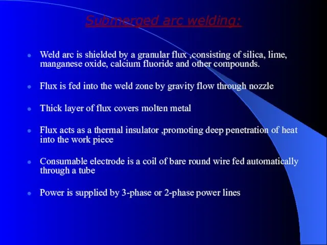
- 18. Submerged arc welding: Weld arc is shielded by a granular flux ,consisting of silica, lime, manganese
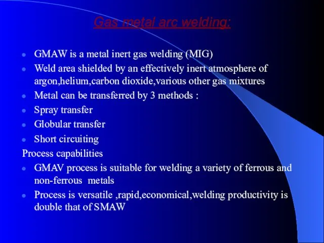
- 19. Gas metal arc welding: GMAW is a metal inert gas welding (MIG) Weld area shielded by
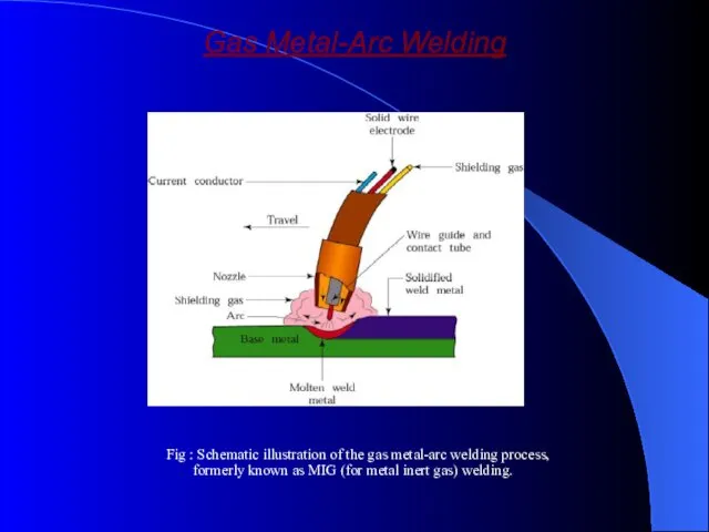
- 20. Gas Metal-Arc Welding Fig : Schematic illustration of the gas metal-arc welding process, formerly known as
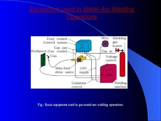
- 21. Equipment used in Metal-Arc Welding Operations Fig : Basic equipment used in gas metal-arc welding operations
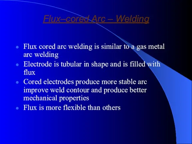
- 22. Flux–cored Arc – Welding Flux cored arc welding is similar to a gas metal arc welding
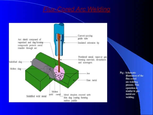
- 23. Flux-Cored Arc Welding Fig : Schematic illustration of the flux-cored arc-welding process. This operation is similar
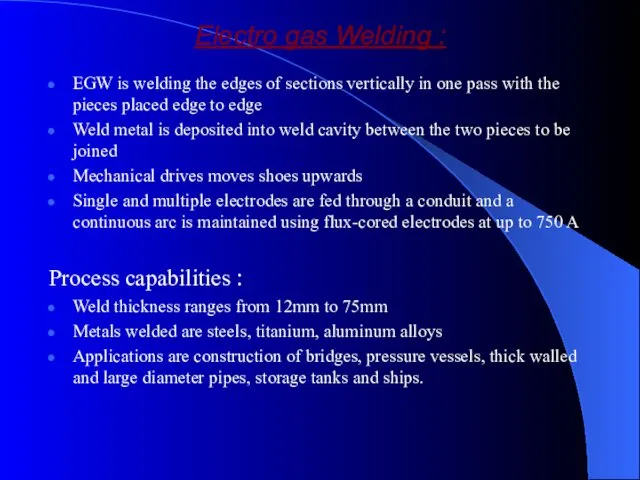
- 24. Electro gas Welding : EGW is welding the edges of sections vertically in one pass with
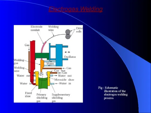
- 25. Electrogas Welding Fig : Schematic illustration of the electrogas welding process
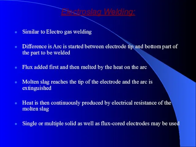
- 26. Electroslag Welding: Similar to Electro gas welding Difference is Arc is started between electrode tip and
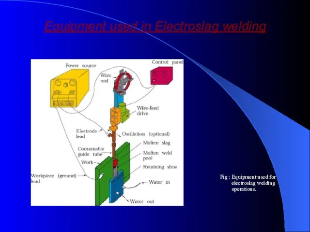
- 27. Equipment used in Electroslag welding Fig : Equipment used for electroslag welding operations.
- 28. Solid-State Welding Processes
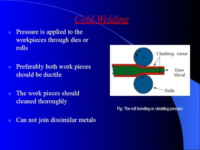
- 29. Cold Welding Pressure is applied to the workpieces through dies or rolls Preferably both work pieces
- 30. Ultrasonic Welding Surfaces of the two components are subjected to a static forces and oscillating shearing
- 31. Friction Welding Developed in the 1940’s Parts are circular in shape Can be used to join
- 32. Process can be fully automated Can weld solid steel bars up to 250mm in outside diameter
- 33. Inertia Friction Welding Modification of Friction Welding Energy is supplied by a fly wheel The parts
- 34. Linear Friction Welding Parts are joined by a linear reciprocating motion Parts do not have to
- 35. Friction Stir Welding (FSW) New Process for welding aerospace metals Research is being directed towards using
- 36. Resistance Welding Developed in the early 1900’s A process in which the heat required for welding
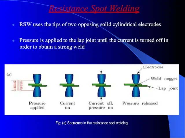
- 37. Resistance Spot Welding RSW uses the tips of two opposing solid cylindrical electrodes Pressure is applied
- 38. Surfaces should be clean Accurate control of and timing of electric current and of pressure are
- 39. Resistance Seam Welding RSEM is modification of spot welding wherein the electrodes are replaced by rotating
- 40. Resistance Projection Welding RPW is developed by introducing high electrical resistance at a joint by embossing
- 41. The electrodes exert pressure to compress the projections Nuts and bolts can be welded to sheet
- 42. Flash Welding Heat is generated from the arc as the ends as the two members contacts
- 44. Скачать презентацию
Purposes of this report: - to give an outline of welding
Purposes of this report: - to give an outline of welding
Diversity of welding processes
welding
Solid state welding
Soldering and brazing
Fusion welding
Electrical energy
Chemical
Diversity of welding processes
welding
Solid state welding
Soldering and brazing
Fusion welding
Electrical energy
Chemical
Solid state welding
It merges all the welding processes in which there
Solid state welding
It merges all the welding processes in which there
Soldering or brazing
In these processes, only the filler metals which join
Soldering or brazing
In these processes, only the filler metals which join
Fusion welding
This process involves the partial melting of the two members
Fusion welding
This process involves the partial melting of the two members
Fusion welding Process
Fusion welding Process
Topics to Discuss
Introduction
Oxyfuel Gas welding
Arc-Welding Processes:Consumable electrode
Electrodes
Arc-Welding Processes:Non Consumable Process
Thermit
Topics to Discuss
Introduction
Oxyfuel Gas welding
Arc-Welding Processes:Consumable electrode
Electrodes
Arc-Welding Processes:Non Consumable Process
Thermit
Introduction
Definition : Fusion Welding is defined as melting together and
Introduction
Definition : Fusion Welding is defined as melting together and
Oxyfuel Gas Welding
Fig : Three basic types of oxyacetylene flames used
Oxyfuel Gas Welding
Fig : Three basic types of oxyacetylene flames used
Oxyfuel Gas Welding
Welding process that uses fuel gas combined with oxygen
Oxyfuel Gas Welding
Welding process that uses fuel gas combined with oxygen
Types of flames
Neutral flame
Oxidising flame
Carburising flame
Filler Metals :
Additional material to weld
Types of flames
Neutral flame
Oxidising flame
Carburising flame
Filler Metals :
Additional material to weld
Welding practice & equipment
STEPS :
Prepare the edges to be joined and
Welding practice & equipment
STEPS :
Prepare the edges to be joined and
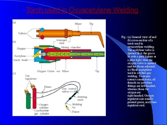
Torch used in Oxyacetylene Welding
Fig : (a) General view of and
Torch used in Oxyacetylene Welding
Fig : (a) General view of and
Arc welding process : Consumable electrode
Process goes with the consumable electrode
Arc welding process : Consumable electrode
Process goes with the consumable electrode
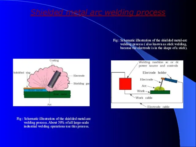
Shielded metal arc welding process
Fig : Schematic illustration of the shielded
Shielded metal arc welding process
Fig : Schematic illustration of the shielded
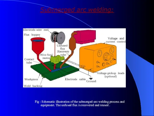
Submerged arc welding:
Fig : Schematic illustration of the submerged-arc welding process
Submerged arc welding:
Fig : Schematic illustration of the submerged-arc welding process
Submerged arc welding:
Weld arc is shielded by a granular flux ,consisting
Submerged arc welding:
Weld arc is shielded by a granular flux ,consisting
Gas metal arc welding:
GMAW is a metal inert gas welding (MIG)
Weld
Gas metal arc welding:
GMAW is a metal inert gas welding (MIG)
Weld
Gas Metal-Arc Welding
Fig : Schematic illustration of the gas metal-arc welding
Gas Metal-Arc Welding
Fig : Schematic illustration of the gas metal-arc welding
Equipment used in Metal-Arc Welding Operations
Fig : Basic equipment used in
Equipment used in Metal-Arc Welding Operations
Fig : Basic equipment used in
Flux–cored Arc – Welding
Flux cored arc welding is similar to a
Flux–cored Arc – Welding
Flux cored arc welding is similar to a
Flux-Cored Arc Welding
Fig : Schematic illustration of the flux-cored arc-welding process.
Flux-Cored Arc Welding
Fig : Schematic illustration of the flux-cored arc-welding process.
Electro gas Welding :
EGW is welding the edges of sections vertically
Electro gas Welding :
EGW is welding the edges of sections vertically
Electrogas Welding
Fig : Schematic illustration of the electrogas welding process
Electrogas Welding
Fig : Schematic illustration of the electrogas welding process
Electroslag Welding:
Similar to Electro gas welding
Difference is Arc is started between
Electroslag Welding:
Similar to Electro gas welding
Difference is Arc is started between
Equipment used in Electroslag welding
Fig : Equipment used for electroslag
Equipment used in Electroslag welding
Fig : Equipment used for electroslag
Solid-State Welding Processes
Solid-State Welding Processes
Cold Welding
Pressure is applied to the workpieces through dies or rolls
Preferably
Cold Welding
Pressure is applied to the workpieces through dies or rolls
Preferably
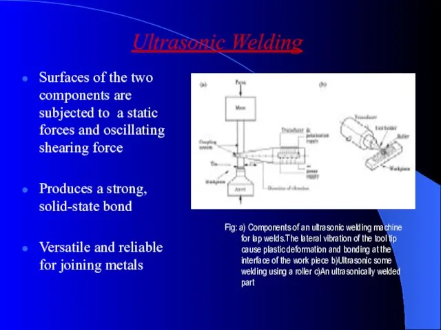
Ultrasonic Welding
Surfaces of the two components are subjected to a static
Ultrasonic Welding
Surfaces of the two components are subjected to a static
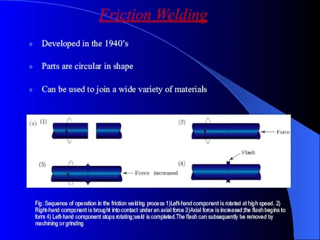
Friction Welding
Developed in the 1940’s
Parts are circular in shape
Can be used
Friction Welding
Developed in the 1940’s
Parts are circular in shape
Can be used
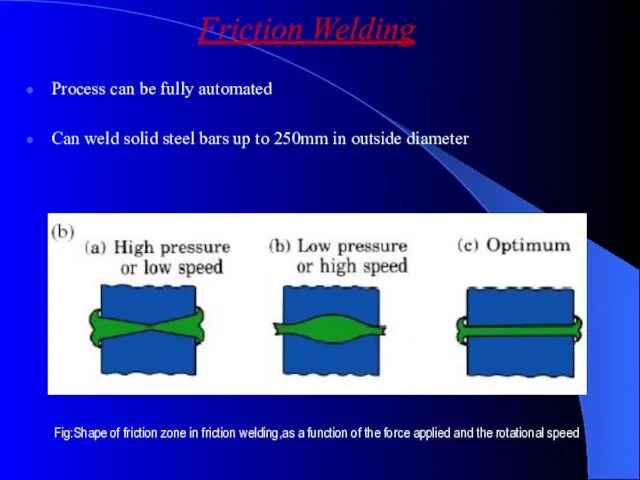
Process can be fully automated
Can weld solid steel bars up to
Process can be fully automated
Can weld solid steel bars up to
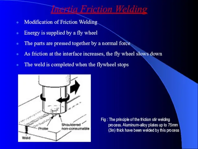
Inertia Friction Welding
Modification of Friction Welding
Energy is supplied by a fly
Inertia Friction Welding
Modification of Friction Welding
Energy is supplied by a fly
Linear Friction Welding
Parts are joined by a linear reciprocating motion
Parts do
Linear Friction Welding
Parts are joined by a linear reciprocating motion
Parts do
Friction Stir Welding (FSW)
New Process for welding aerospace metals
Research is being
Friction Stir Welding (FSW)
New Process for welding aerospace metals
Research is being
Resistance Welding
Developed in the early 1900’s
A process in which the heat
Resistance Welding
Developed in the early 1900’s
A process in which the heat
Resistance Spot Welding
RSW uses the tips of two opposing solid cylindrical
Resistance Spot Welding
RSW uses the tips of two opposing solid cylindrical
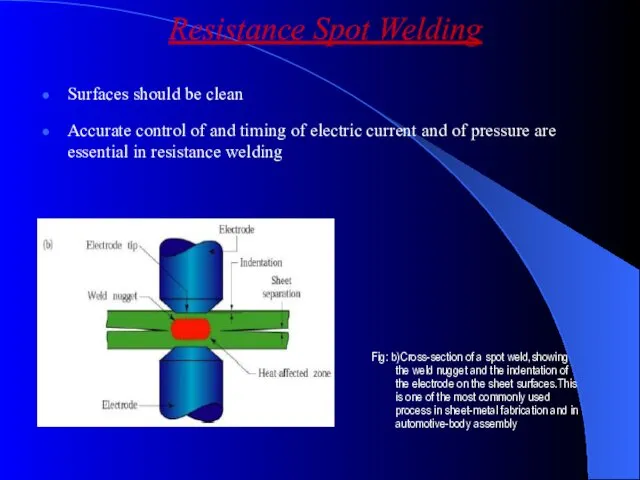
Surfaces should be clean
Accurate control of and timing of electric current
Surfaces should be clean
Accurate control of and timing of electric current
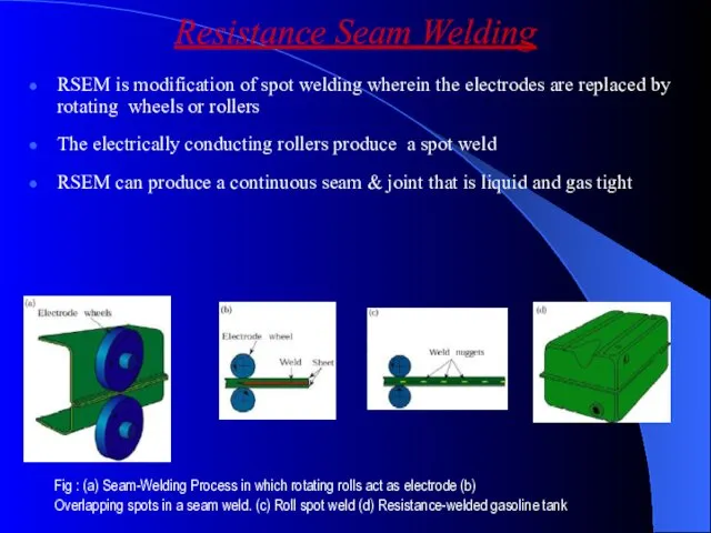
Resistance Seam Welding
RSEM is modification of spot welding wherein the electrodes
Resistance Seam Welding
RSEM is modification of spot welding wherein the electrodes
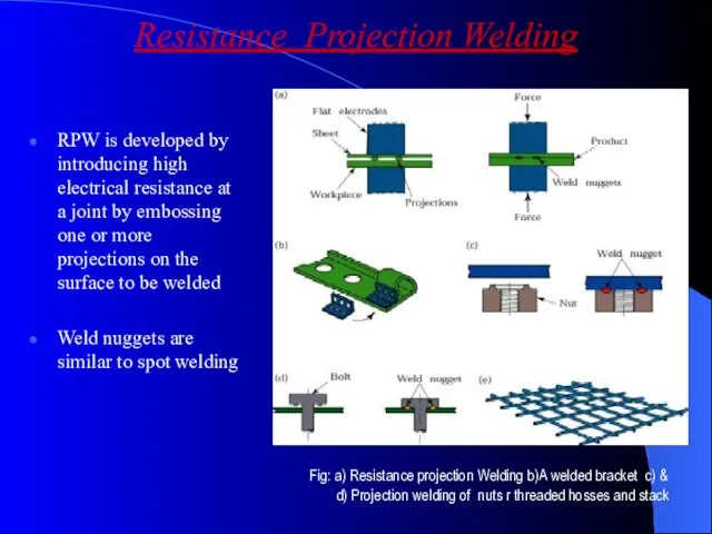
Resistance Projection Welding
RPW is developed by introducing high electrical resistance at
Resistance Projection Welding
RPW is developed by introducing high electrical resistance at
The electrodes exert pressure to compress the projections
Nuts and bolts can
The electrodes exert pressure to compress the projections
Nuts and bolts can
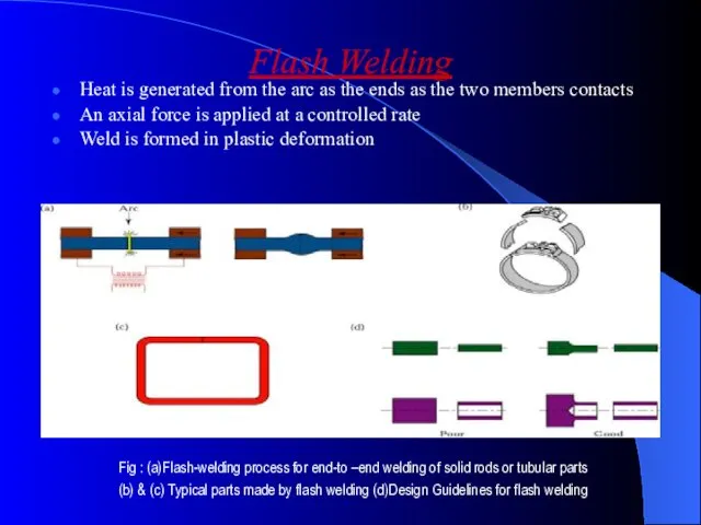
Flash Welding
Heat is generated from the arc as the ends as
Flash Welding
Heat is generated from the arc as the ends as
 Past Simple. Простое прошедшее время
 СССР в годы перестройки
 Электричество
 Презентация : Авторитарное воспитание детей
 Автоматические выключатели
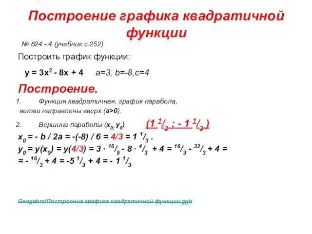 Построение графика квадратичной функции
 Способы преобразования ортогональных проекций
 Презентация Узнай, кто это! (1 тип слоговой структуры слова)
 Анализ работы отделения медицинской реабилитации 29-й городской поликлиники за 1 квартал 2015 года
 Электрическая схема тепловоза ТЭМ-18Д
 Эра-Глонасс. Устройство вызова экстренных оперативных служб
 Это интересно- Шведская система образования
 Автомобиль. Самобеглая коляска
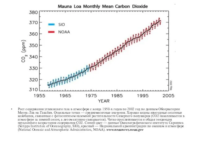 Глобальное потепление
 Презентация социального проекта к 65-летию Победы Следы войны под нашими крышами
 Презентация по творчеству М. В.Ломоносова
 Формы социального обслуживания пожилых граждан и инвалидов
 Из истории интересных чисел. Число П
 Автомобиль. Дорога. Пешеход
 Презентация к уроку по курсу ОРКСЭ. Тема: Совесть (ОСЭ) 4 класс.
 Проект Моя буква.
 Устройства для нагревания воздуха. Очистка вентиляционного воздуха. Системы местной вентиляции. (Лекция 8)
 Багатоповерхові будівлі. Планувальні схеми
 Good health is above wealth
 Основное оборудование ТЭС
 Тримаран для запуска космических ракет. Пошаговое изготовление
 Классификация яхт
 Конструкция скважин