- Alternating Current motors

Содержание
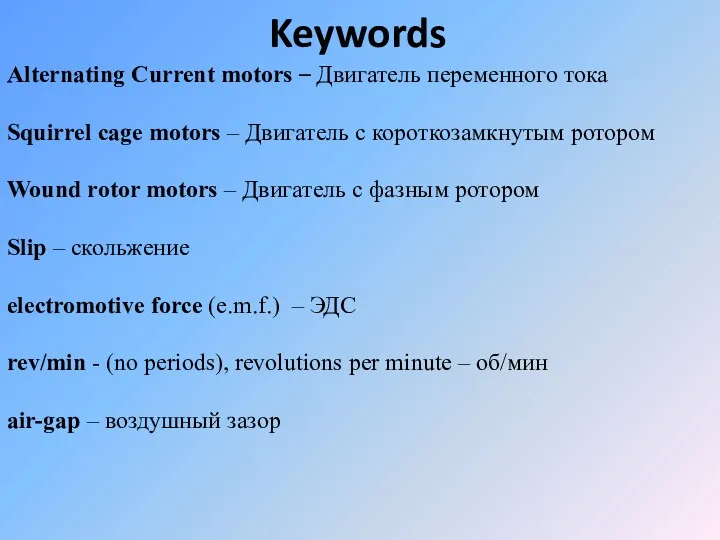
- 2. Keywords Alternating Current motors – Двигатель переменного тока Squirrel cage motors – Двигатель с короткозамкнутым ротором
- 3. Switched Reluctance Motor – коммутируемый реактивный электродвигатель, двигатель с регулируемым магнитным сопротивлением p.u. (per unit) -
- 4. ABBREVIATIONS BLAC - Brushless AC BLDC - Brushless DC BLDM - Brushless DC motor EC -
- 5. Сlassification AC motor
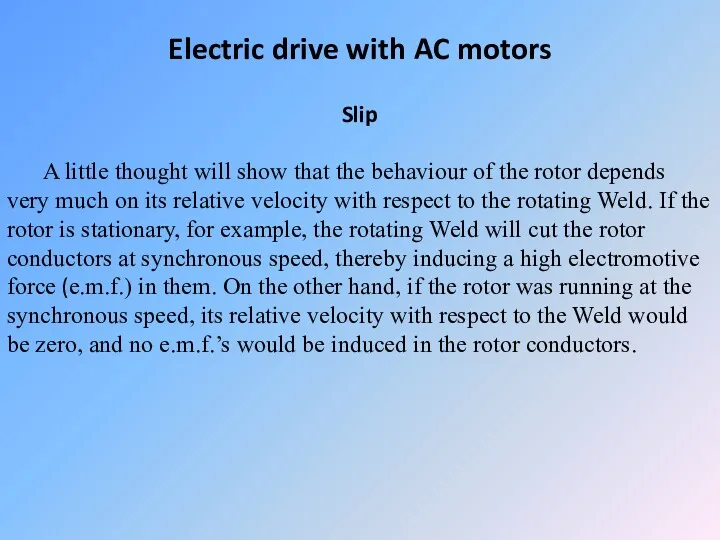
- 6. Electric drive with AC motors Slip A little thought will show that the behaviour of the
- 7. The relative velocity between the rotor and the field is known as the slip. If the
- 8. A slip of 0 therefore indicates that the rotor speed is equal to the synchronous speed,
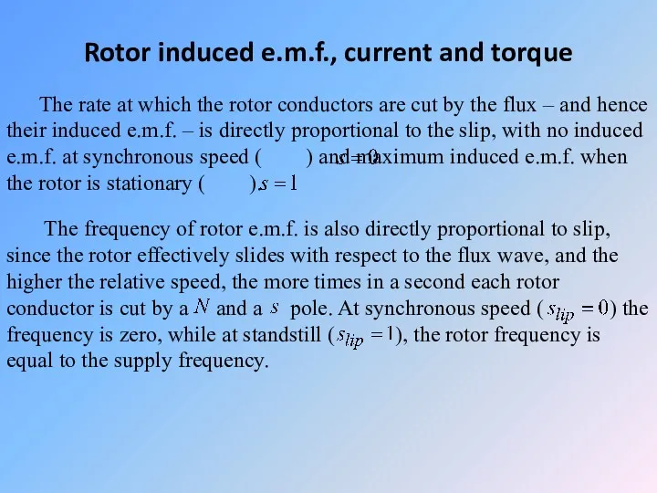
- 9. Rotor induced e.m.f., current and torque The rate at which the rotor conductors are cut by
- 10. These relationships are shown in Figure Variation of rotor induced e.m.f and frequency with speed and
- 11. Rotor currents and torque – small slip When the slip is small (say between 0 and
- 12. This situation was assumed in the previous discussion, and is represented by the space waveforms shown
- 13. To calculate the torque we need to evaluate the ‘BIlr’ product to obtain the tangential force
- 14. We don’t need to work out the torque in detail, but it should be clear that
- 15. Provided that there are a large number of rotor bars (which is a safe bet in
- 16. The torque–speed (and torque/slip) relationship for small slips is thus approximately a straight-line, as shown by
- 17. If the motor is unloaded, it will need very little torque to keep running – only
- 18. Induction motors are usually designed so that their full-load torque is developed for small values of
- 19. We note that, in this normal operating region, the torque–speed curve is very similar to that
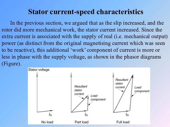
- 20. Stator current-speed characteristics In the previous section, we argued that as the slip increased, and the
- 21. The resultant stator current is the sum of the magnetising current, which is present all the
- 22. Very high starting currents are one of the worst features of the cage induction motor. They
- 23. The torque and current axes are scaled so that 100% represents the continuously rated (full-load) value
- 24. As the speed dropped, the motor torque would rise, until a new equilibrium was reached, at
- 25. The speed therefore falls faster and faster, and the motor is said to be ‘stalling’. With
- 26. Torque–speed curves – influence of rotor parameters We saw earlier that the rotor resistance and reactance
- 27. Types of AC drives Cage rotor For small values of slip, i.e. in the normal running
- 28. So, we conclude that the low-resistance rotor not only gives better speed holding, but is also
- 29. Altering the rotor resistance has little or no effect on the value of the peak (pullout)
- 30. There are some applications for which high-resistance motors are well suited, an example being for metal
- 31. To sum up, a high-rotor resistance is desirable when starting and at low speeds, while a
- 32. Double cage rotors Double cage rotors have an outer cage made up of relatively high resistivity
- 33. The inner cage is sunk deep into the rotor, so that it is almost completely surrounded
- 34. At the normal running speed the roles are reversed. The rotor frequency is low, so both
- 35. Wound Rotor Motors Older motor designed to operate at “variable speed” • Advantages – Speed Control,
- 36. Switched Reluctance Motor (SRM) The advantage of a switched reluctance motor is high torque at low
- 37. Starting and run-up of slipring motors By adding external resistance in series with the rotor windings
- 38. The influence of rotor resistance is shown by the set of torque–speed curves in Figure. The
- 39. A high-rotor resistance is used when the motor is first switched on, and depending on the
- 40. As the speed rises, the torque would fall more or less linearly if the resistance remained
- 41. As mentioned earlier, the total energy dissipated in the rotor circuit during run-up is equal to
- 42. The resistance between the electrodes depends on how far they are immersed in the liquid. The
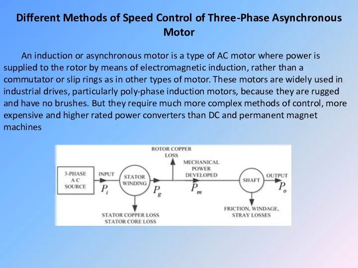
- 43. Different Methods of Speed Control of Three-Phase Asynchronous Motor An induction or asynchronous motor is a
- 44. Single-phase versions are used in small appliances. Their speed is determined by the frequency of the
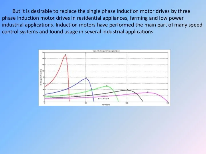
- 47. But it is desirable to replace the single phase induction motor drives by three phase induction
- 48. The benefit of improvement in the motor drive industry has touched varied applications, from heavy and
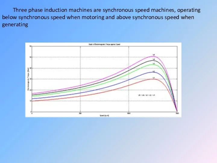
- 49. Three phase induction machines are synchronous speed machines, operating below synchronous speed when motoring and above
- 51. Скачать презентацию
Keywords
Alternating Current motors – Двигатель переменного тока
Squirrel cage motors – Двигатель
Keywords
Alternating Current motors – Двигатель переменного тока
Squirrel cage motors – Двигатель
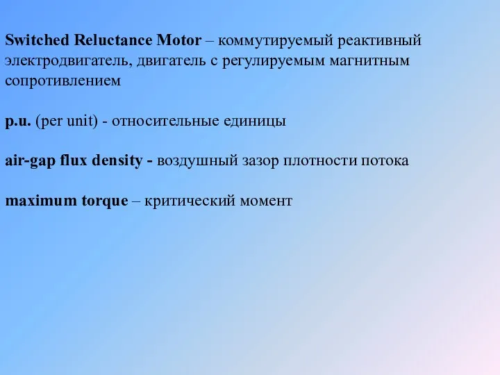
Switched Reluctance Motor – коммутируемый реактивный электродвигатель, двигатель с регулируемым магнитным
Switched Reluctance Motor – коммутируемый реактивный электродвигатель, двигатель с регулируемым магнитным
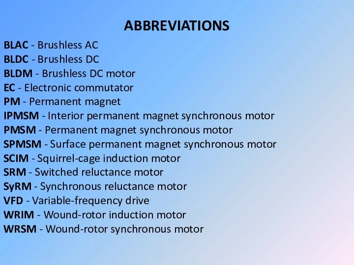
ABBREVIATIONS
BLAC - Brushless AC
BLDC - Brushless DC
BLDM - Brushless DC motor
EC - Electronic
ABBREVIATIONS
BLAC - Brushless AC
BLDC - Brushless DC
BLDM - Brushless DC motor
EC - Electronic
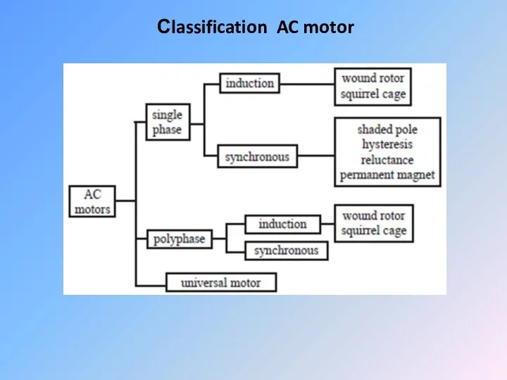
Сlassification AC motor
Сlassification AC motor
Electric drive with AC motors
Slip
A little thought will show that the
Electric drive with AC motors
Slip
A little thought will show that the
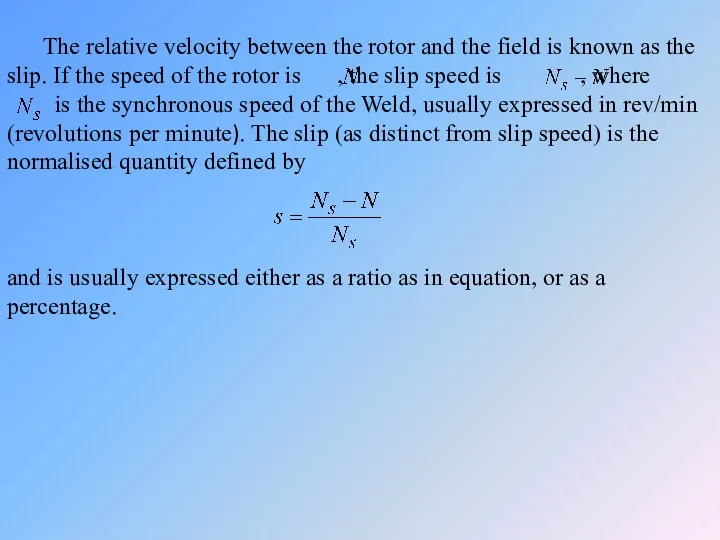
The relative velocity between the rotor and the field is known
The relative velocity between the rotor and the field is known
A slip of 0 therefore indicates that the rotor speed is
A slip of 0 therefore indicates that the rotor speed is
Rotor induced e.m.f., current and torque
The rate at which the rotor
Rotor induced e.m.f., current and torque
The rate at which the rotor
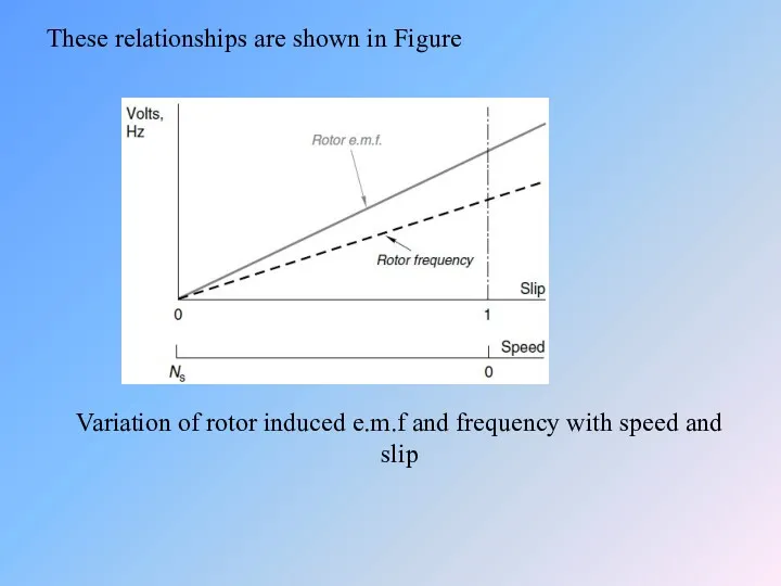
These relationships are shown in Figure
Variation of rotor induced e.m.f and
These relationships are shown in Figure
Variation of rotor induced e.m.f and
Rotor currents and torque – small slip
When the slip is small
Rotor currents and torque – small slip
When the slip is small
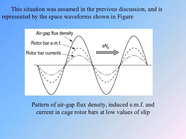
This situation was assumed in the previous discussion, and is represented
This situation was assumed in the previous discussion, and is represented
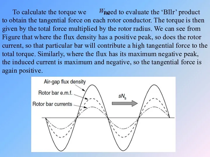
To calculate the torque we need to evaluate the ‘BIlr’ product
To calculate the torque we need to evaluate the ‘BIlr’ product
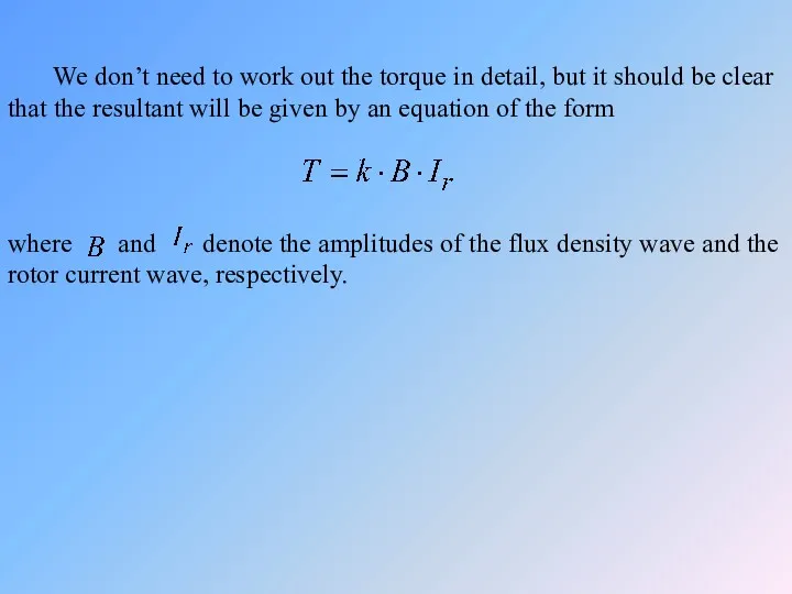
We don’t need to work out the torque in detail,
We don’t need to work out the torque in detail,
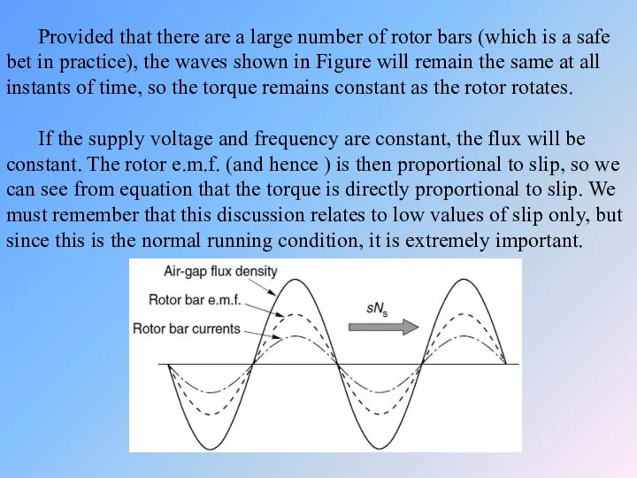
Provided that there are a large number of rotor bars (which
Provided that there are a large number of rotor bars (which
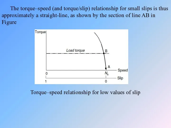
The torque–speed (and torque/slip) relationship for small slips is thus approximately
The torque–speed (and torque/slip) relationship for small slips is thus approximately
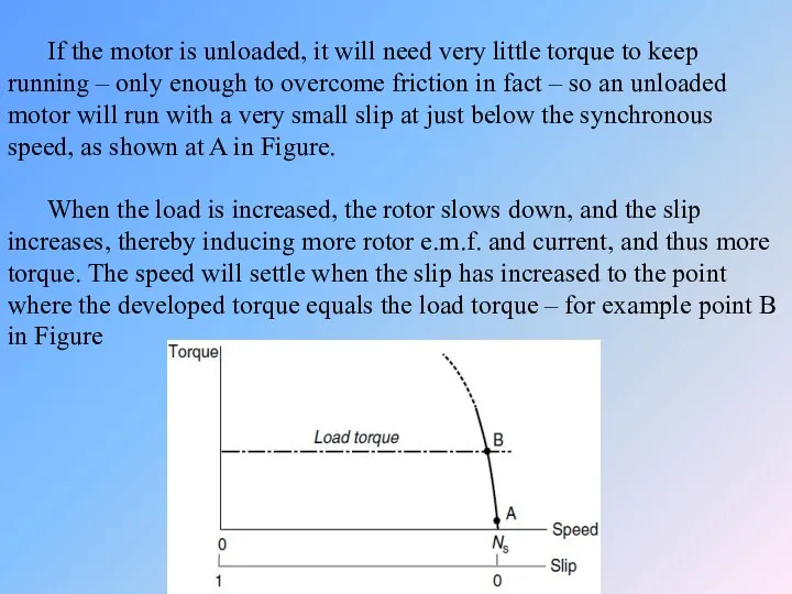
If the motor is unloaded, it will need very little torque
If the motor is unloaded, it will need very little torque
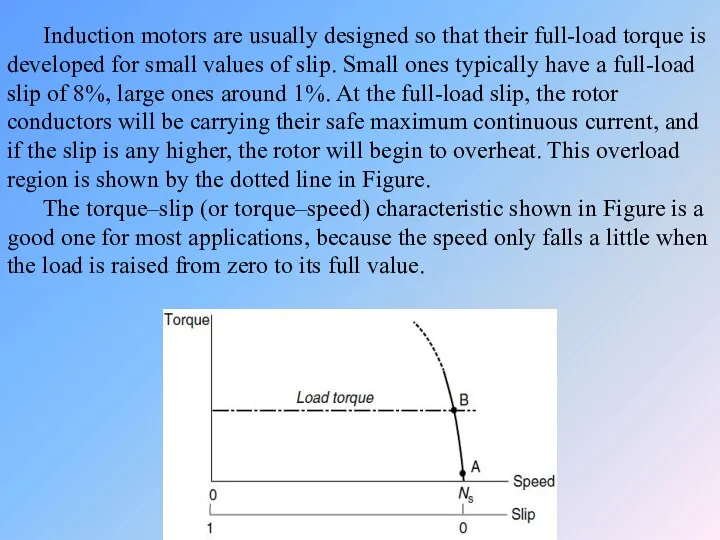
Induction motors are usually designed so that their full-load torque is
Induction motors are usually designed so that their full-load torque is
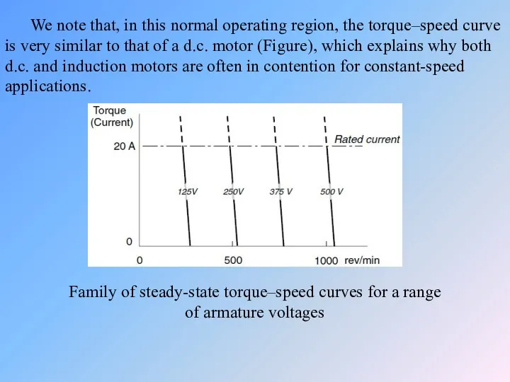
We note that, in this normal operating region, the torque–speed curve
We note that, in this normal operating region, the torque–speed curve
Stator current-speed characteristics
In the previous section, we argued that as the
Stator current-speed characteristics
In the previous section, we argued that as the
The resultant stator current is the sum of the magnetising current,
The resultant stator current is the sum of the magnetising current,
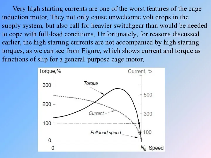
Very high starting currents are one of the worst features of
Very high starting currents are one of the worst features of
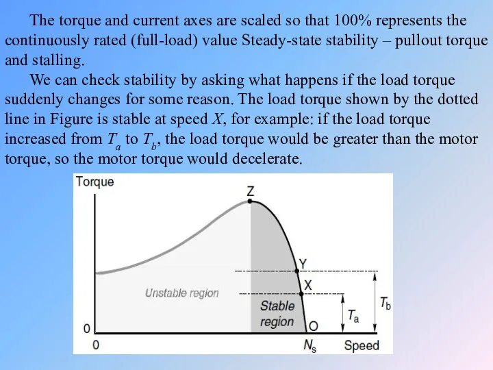
The torque and current axes are scaled so that 100% represents
The torque and current axes are scaled so that 100% represents

As the speed dropped, the motor torque would rise, until a
As the speed dropped, the motor torque would rise, until a
The speed therefore falls faster and faster, and the motor is
The speed therefore falls faster and faster, and the motor is
Torque–speed curves – influence of rotor parameters
We saw earlier that the
Torque–speed curves – influence of rotor parameters
We saw earlier that the
Types of AC drives
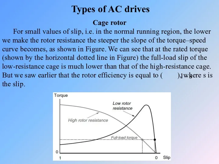
Cage rotor
For small values of slip, i.e. in
Types of AC drives
Cage rotor
For small values of slip, i.e. in
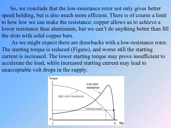
So, we conclude that the low-resistance rotor not only gives better
So, we conclude that the low-resistance rotor not only gives better
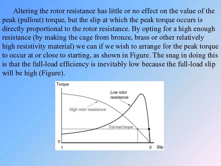
Altering the rotor resistance has little or no effect on the
Altering the rotor resistance has little or no effect on the
There are some applications for which high-resistance motors are well suited,
There are some applications for which high-resistance motors are well suited,
To sum up, a high-rotor resistance is desirable when starting and
To sum up, a high-rotor resistance is desirable when starting and
Double cage rotors
Double cage rotors have an outer cage made up
Double cage rotors
Double cage rotors have an outer cage made up
The inner cage is sunk deep into the rotor, so that
The inner cage is sunk deep into the rotor, so that
At the normal running speed the roles are reversed. The rotor
At the normal running speed the roles are reversed. The rotor
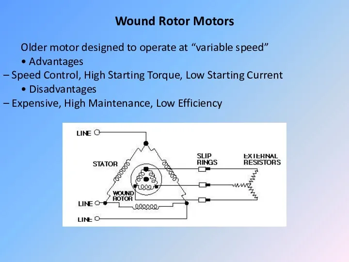
Wound Rotor Motors
Older motor designed to operate at “variable speed”
• Advantages
–
Wound Rotor Motors
Older motor designed to operate at “variable speed”
• Advantages
–
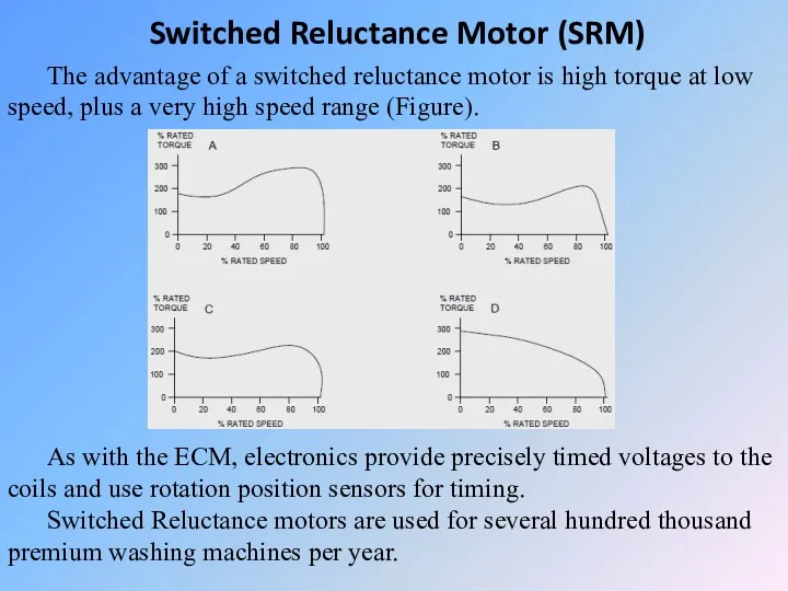
Switched Reluctance Motor (SRM)
The advantage of a switched reluctance motor is
Switched Reluctance Motor (SRM)
The advantage of a switched reluctance motor is
Starting and run-up of slipring motors
By adding external resistance in series
Starting and run-up of slipring motors
By adding external resistance in series
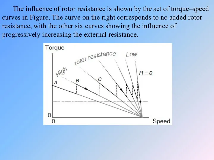
The influence of rotor resistance is shown by the set of
The influence of rotor resistance is shown by the set of
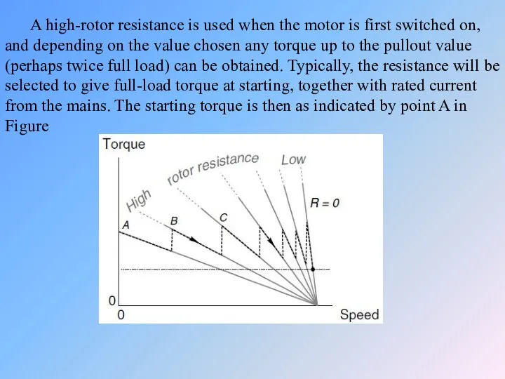
A high-rotor resistance is used when the motor is first switched
A high-rotor resistance is used when the motor is first switched
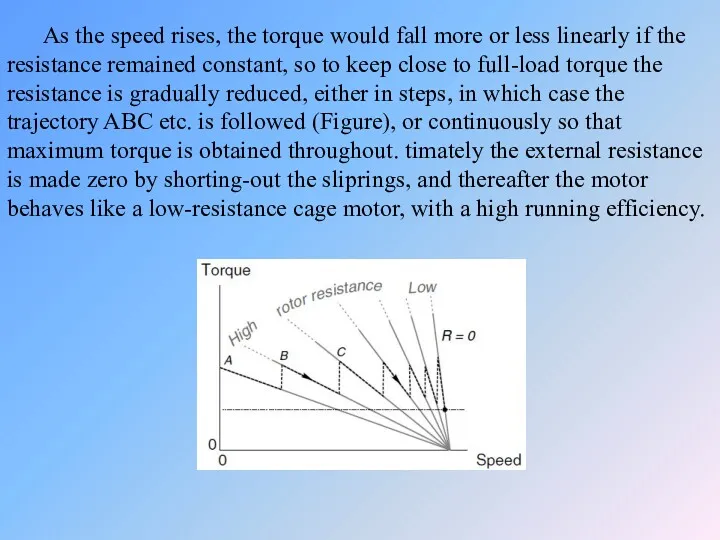
As the speed rises, the torque would fall more or less
As the speed rises, the torque would fall more or less
As mentioned earlier, the total energy dissipated in the rotor circuit
As mentioned earlier, the total energy dissipated in the rotor circuit
The resistance between the electrodes depends on how far they are
The resistance between the electrodes depends on how far they are
Different Methods of Speed Control of Three-Phase Asynchronous Motor
An induction or
Different Methods of Speed Control of Three-Phase Asynchronous Motor
An induction or
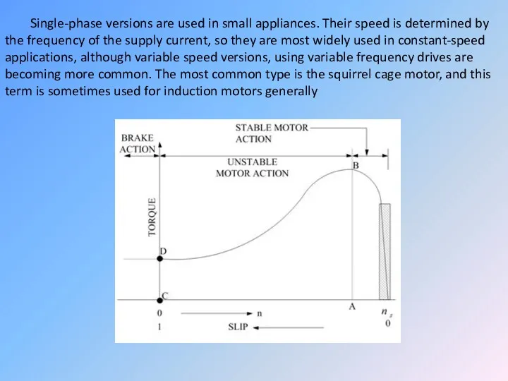
Single-phase versions are used in small appliances. Their speed is determined
Single-phase versions are used in small appliances. Their speed is determined
But it is desirable to replace the single phase induction motor
But it is desirable to replace the single phase induction motor

The benefit of improvement in the motor drive industry has touched
The benefit of improvement in the motor drive industry has touched
Three phase induction machines are synchronous speed machines, operating below synchronous
Three phase induction machines are synchronous speed machines, operating below synchronous
 Лампа накаливания
 Пара сил. Статика
 Движение электрона в атоме
 Магнитное поле. Электромагниты. Применение электромагнитов
 Проблемы современной физики
 Механика жидкостей и газов. (Лекция 9)
 Разработка урока по теме Деление ядер урана. Цепная реакция
 Паровая турбина. КПД теплового двигателя
 Реактивное движение
 Електричний струм у рідинах
 Техническое обслуживание и технология ремонта аккумуляторных батарей
 Сполучені посудини. Манометри
 Сложные электрические цепи
 Презентация к уроку по теме Механическая работа 7 класс
 Никола Тесла
 Радіоактивність. Радіоактивні випромінювання
 Istoria electricitatii
 Действие жидкости и газа на погруженное в них тело
 Виды теплопередачи
 Архимедова сила
 Нелинейные волны в жидкости. Солитоны. Лекция 6
 Решение задач по теме Законы Ньютона
 Электрические явления презентация к открытому уроку 8 класс
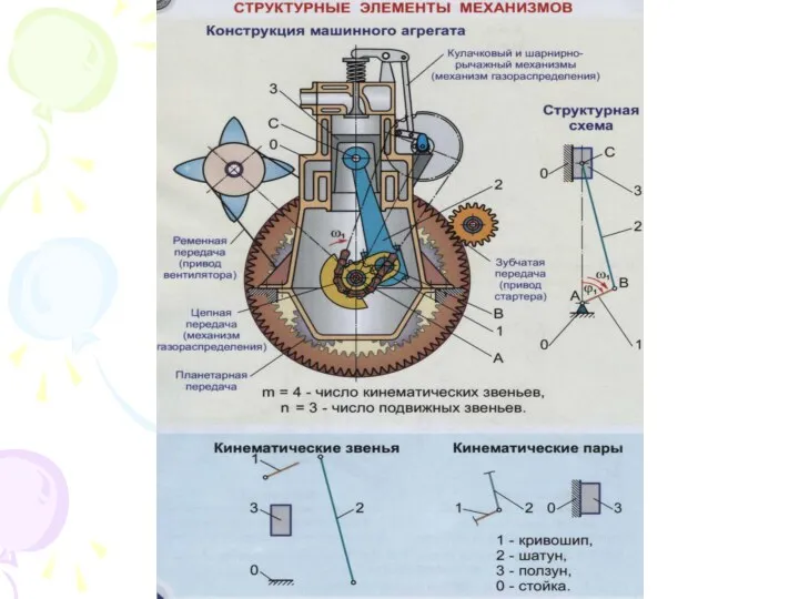 Структурные элементы механизмов
 Моторизованный микроскоп. Съемка живых клеток
 Архимедова сила
 Mechanics. Kinematics
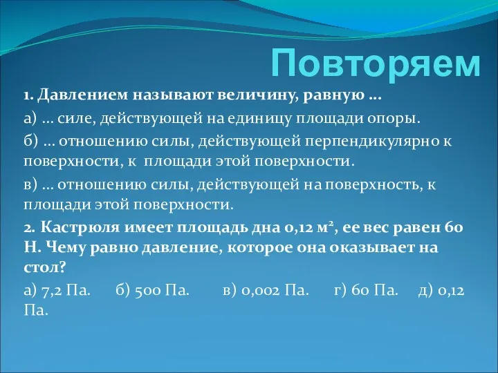 Презентация к уроку по теме Атмосферное давление. Опыт Торричелли