- DSI M78 6-Speed A/T. Overseas service team

Содержание
- 2. 4-Speed vs 6-Speed
- 3. Advanced features for M78 A/T Early down shift (shift skip) with hard braking Gear holding when
- 4. Components Front band Rear band
- 5. Valve body S2 S3 S4 S1 S10(NL) S9(NH) S5 (NH) S8 (NL) S6(NH) Oil temp. sensor
- 6. Single planetary gear set
- 7. Clutch pack *Dynamic pressure equalization ->Reliable clutch engagement and release ->Improved shift refinement
- 8. Double planetary gear set
- 9. Brake band B1(Front band) B2(Rear band) B2
- 10. Clutch pack / Brake band (M74) Clutch pack Brake band C1 C2 C3 B1 B2 2nd,
- 11. Clutch disc pack / Brake band(M78) Clutch pack Brake band C1 C2 C3 B1 B2 Hold
- 12. Shifting components
- 13. Torque converter Plate connected to Lock up clutch Lock up clutch piston Space Torque converter cover
- 14. Oil pump 17.6cc / revolution (Sun gear)
- 15. Oil cooler 28mm 292.1mm 24.3mm 44mm 292.1mm 25.6mm
- 16. Hydraulic circuit
- 17. 1st – 3.53:1(C2 & OWC)
- 18. M 1st – 3.53:1(C2 & B2)
- 19. 2nd – 2.14:1(C2 & B1)
- 20. 2nd(L/Up) – 2.14:1(C2 & B1 & TCC)
- 21. 3rd – 1.48:1(C2 & C3)
- 22. 4th(4th in LHM) – 1.16:1(C1 & C2)
- 23. 5th – 0.87:1(C1 & C3)
- 24. 6th - 0.68:1(C1 & B1)
- 25. Reverse – 3.09:1(C3 & B2)
- 26. Reverse in LHM – 3.09:1(C3 & B2)
- 27. Neutral
- 28. Parking
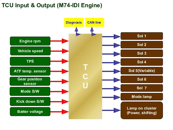
- 29. T C U Diagnosis CAN line Sol 1 Sol 2 Sol 7 Sol 3 Sol 4
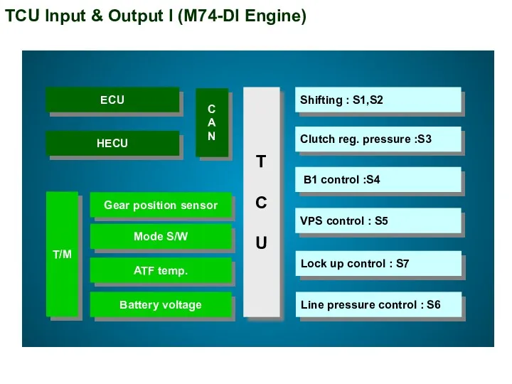
- 30. T C U TCU Input & Output I (M74-DI Engine)
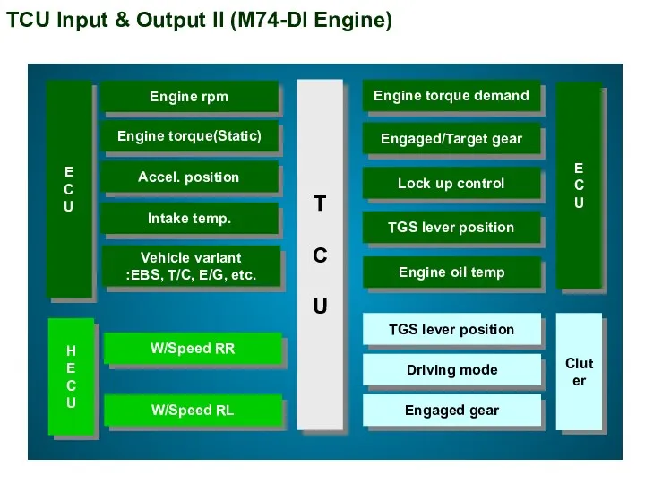
- 31. T C U Engine torque demand Engaged/Target gear Lock up control TGS lever position Engine oil
- 32. TCU Input & Output (M78) T C U IGN Ground EMM Input speed sensor Output speed
- 33. TCU Input & Output (M78) - CAN Selector lever position Selected gear state Manual mode operation
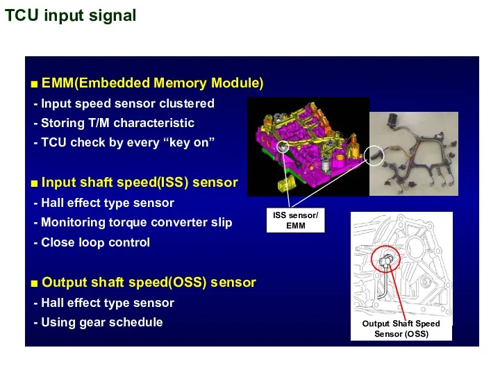
- 34. TCU input signal ■ EMM(Embedded Memory Module) - Input speed sensor clustered - Storing T/M characteristic
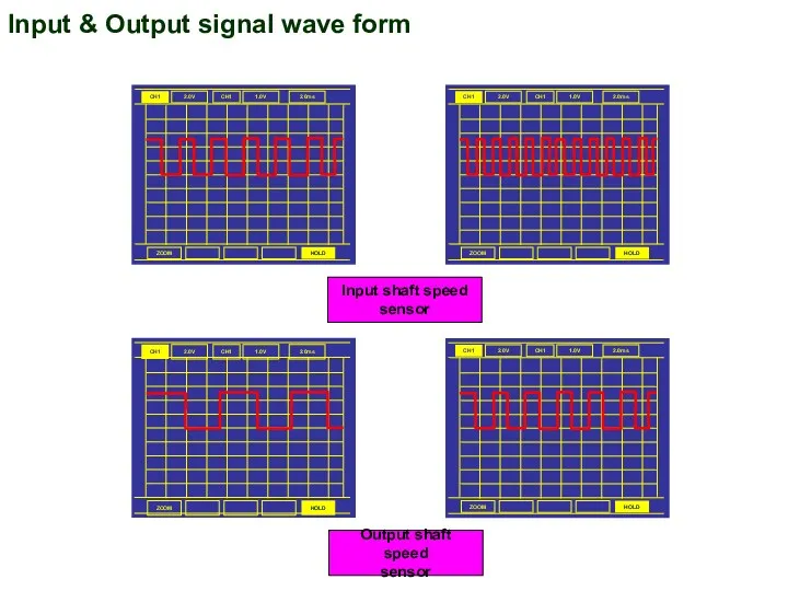
- 35. Input & Output signal wave form CH1 2.0V CH1 1.0V 2.0ms ZOOM HOLD CH1 2.0V CH1
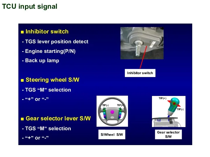
- 36. TCU input signal ■ Inhibitor switch - TGS lever position detect - Engine starting(P/N) - Back
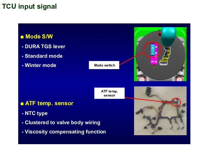
- 37. TCU input signal ■ Mode S/W - DURA TGS lever - Standard mode - Winter mode
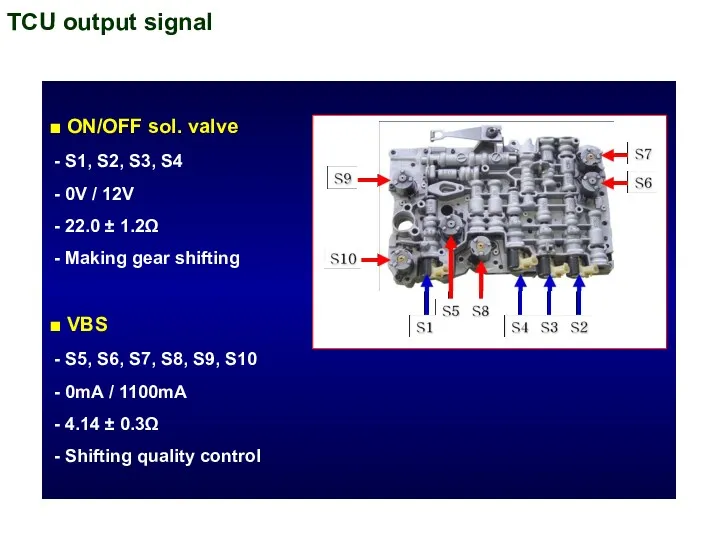
- 38. TCU output signal ■ ON/OFF sol. valve - S1, S2, S3, S4 - 0V / 12V
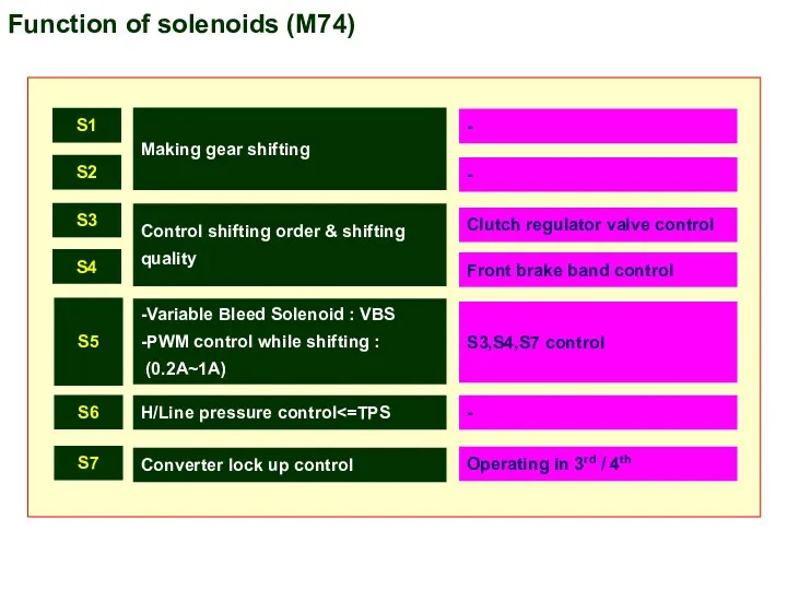
- 39. S1 S2 S3 S4 S5 S6 S7 Making gear shifting - - Control shifting order &
- 40. ON/OFF solenoid Variable Bleed Solenoid S1 S2 S3 S5 S6 C1 supply pre. control C1 supply/release
- 41. T/M control monitoring by TCU ■ Supply voltage monitoring - Voltage sensor inside TCU ■ Solenoid
- 42. Shift energy management ■ Engine output torque increase/decrease - Improved durability by shortening the slipping time.
- 43. Shift map selection ■ Normal mode - Mode S/W : “S” - “D” position - Normal
- 44. Shift map selection II ■ Hot mode - 110℃ ~ 145℃ - Lock up state is
- 45. Connectors Wire harness connector TCU T/M Assy Inhibitor switch
- 46. Electric wiring diagram
- 47. Maintenance - Applying hand brake -> Engine running -> Braking in max load -> TGS lever
- 48. 2. Green offset ■ After T/M assembly replacement - Connect the SCAN100 to the diagnostic connector
- 49. 3. Adaptive reset ■ After T/M or TCU replacement - Connect the SCAN100 to the diagnostic
- 50. 4. Oil check ■ ATF specified - Caltex PED 1712 ATF ■ Check procedure - Drive
- 51. DURA TGS lever TIP(-) TIP(+) Step gate type POWER/NORMAL/WINTER “M” mode (manual) Standard / Winter
- 52. TGS lever position Function Parking (P-lock), Starting Reverse driving Neutral, Starting, Towing (Only for short distance)
- 53. Shifting mode Manual Up / Down shift Knob & S/Wheel Up/Down signal detect Manual mode Operating
- 54. Tip switch in S/Wheel 3.24㏀ 1.62㏀ 845Ω DOWN UP Signal Ground Right tip switch Left tip
- 55. Mode switch Standard mode Winter mode Starting in 1st shifting Gradient : Approx.10% Full (Full Throttle)
- 56. TGS lever control unit 1 2 3 4 5 6 7 8 9 10 W/S switch
- 58. Скачать презентацию
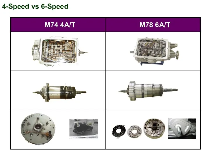
4-Speed vs 6-Speed
4-Speed vs 6-Speed
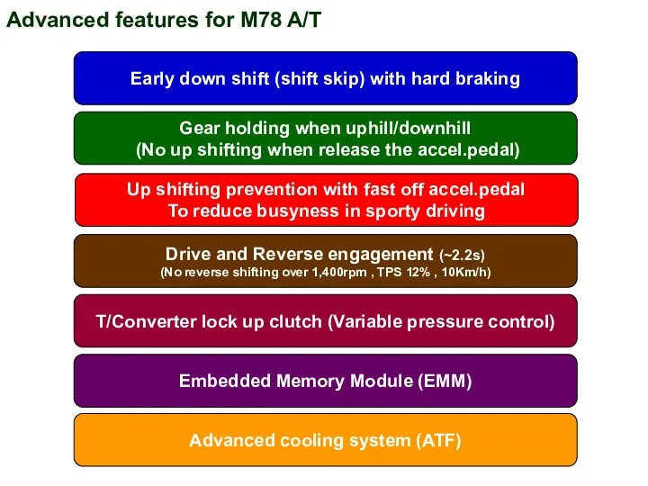
Advanced features for M78 A/T
Early down shift (shift skip) with hard
Advanced features for M78 A/T
Early down shift (shift skip) with hard
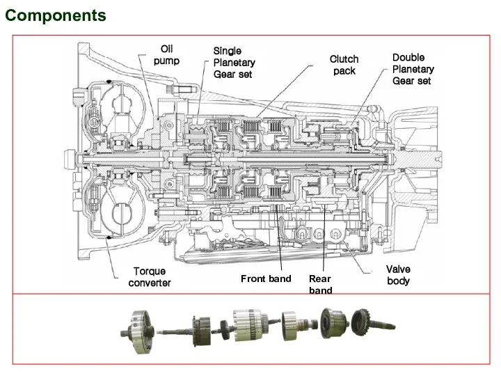
Components
Front band
Rear band
Components
Front band
Rear band
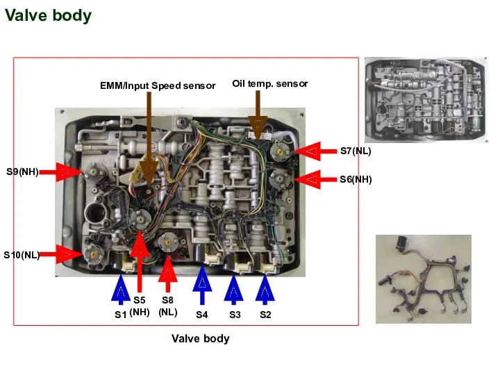
Valve body
S2
S3
S4
S1
S10(NL)
S9(NH)
S5
(NH)
S8
(NL)
S6(NH)
Oil temp. sensor
EMM/Input Speed sensor
S7(NL)
Valve body
Valve body
S2
S3
S4
S1
S10(NL)
S9(NH)
S5
(NH)
S8
(NL)
S6(NH)
Oil temp. sensor
EMM/Input Speed sensor
S7(NL)
Valve body
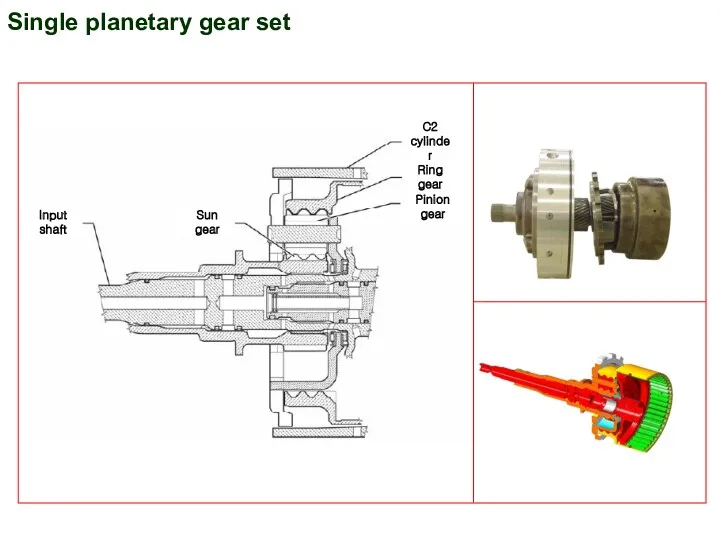
Single planetary gear set
Single planetary gear set
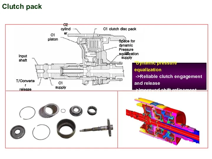
Clutch pack
*Dynamic pressure equalization
->Reliable clutch engagement
and release
->Improved shift refinement
Clutch pack
*Dynamic pressure equalization
->Reliable clutch engagement
and release
->Improved shift refinement
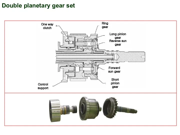
Double planetary gear set
Double planetary gear set
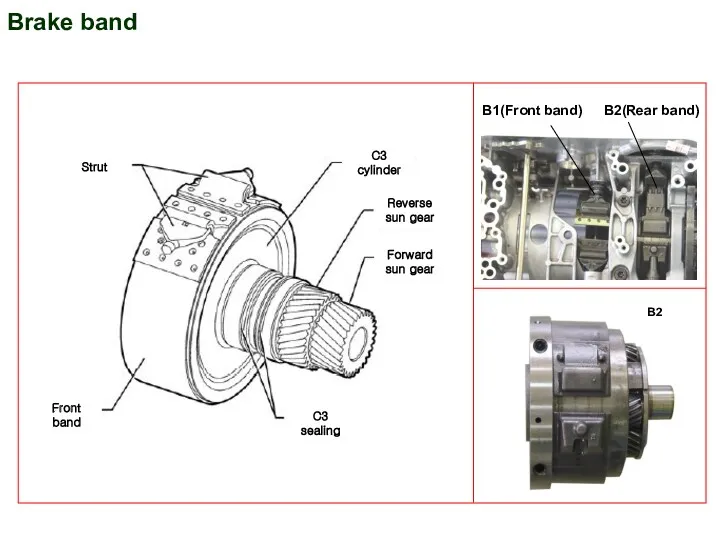
Brake band
B1(Front band)
B2(Rear band)
B2
Brake band
B1(Front band)
B2(Rear band)
B2
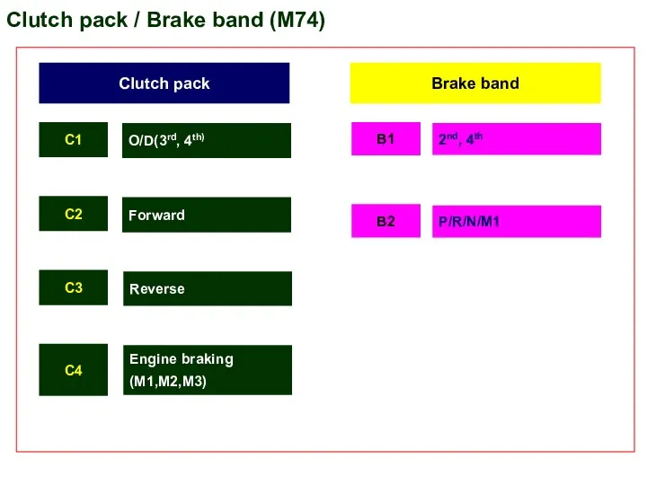
Clutch pack / Brake band (M74)
Clutch pack
Brake band
C1
C2
C3
B1
B2
2nd, 4th
Reverse
P/R/N/M1
O/D(3rd, 4th)
Forward
C4
Engine
Clutch pack / Brake band (M74)
Clutch pack
Brake band
C1
C2
C3
B1
B2
2nd, 4th
Reverse
P/R/N/M1
O/D(3rd, 4th)
Forward
C4
Engine
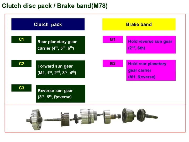
Clutch disc pack / Brake band(M78)
Clutch pack
Brake band
C1
C2
C3
B1
B2
Hold reverse sun gear
Clutch disc pack / Brake band(M78)
Clutch pack
Brake band
C1
C2
C3
B1
B2
Hold reverse sun gear
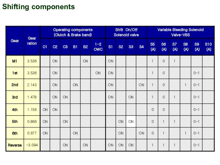
Shifting components
Shifting components
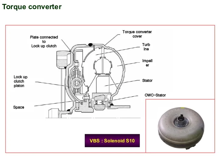
Torque converter
Plate connected to
Lock up clutch
Lock up clutch
piston
Space
Torque converter cover
Turbine
Impeller
OWC-Stator
Stator
VBS :
Torque converter
Plate connected to
Lock up clutch
Lock up clutch
piston
Space
Torque converter cover
Turbine
Impeller
OWC-Stator
Stator
VBS :
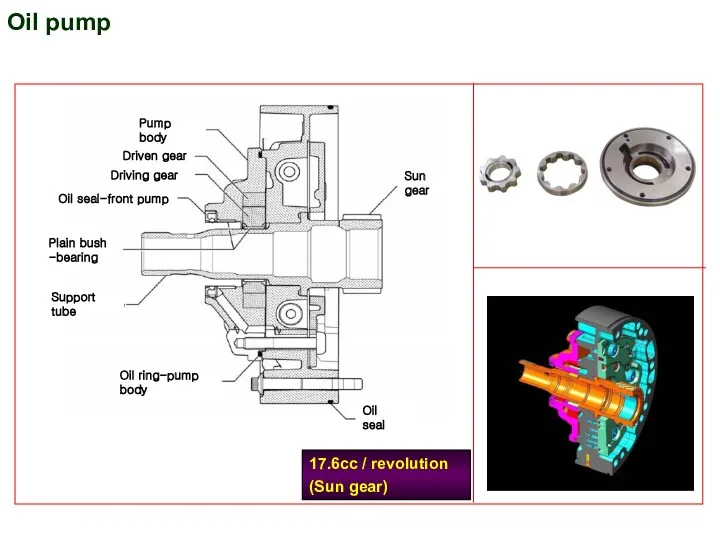
Oil pump
17.6cc / revolution
(Sun gear)
Oil pump
17.6cc / revolution
(Sun gear)
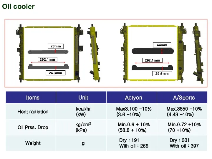
Oil cooler
28mm
292.1mm
24.3mm
44mm
292.1mm
25.6mm
Oil cooler
28mm
292.1mm
24.3mm
44mm
292.1mm
25.6mm
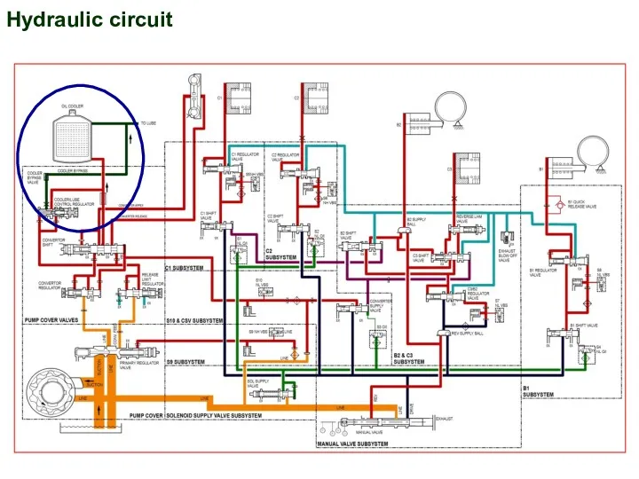
Hydraulic circuit
Hydraulic circuit
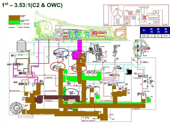
1st – 3.53:1(C2 & OWC)
1st – 3.53:1(C2 & OWC)
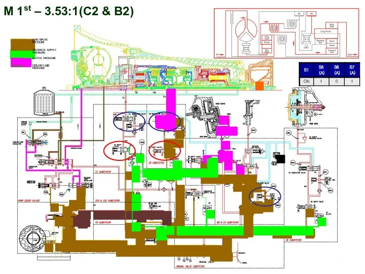
M 1st – 3.53:1(C2 & B2)
M 1st – 3.53:1(C2 & B2)
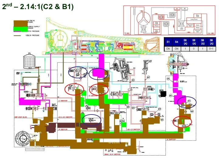
2nd – 2.14:1(C2 & B1)
2nd – 2.14:1(C2 & B1)
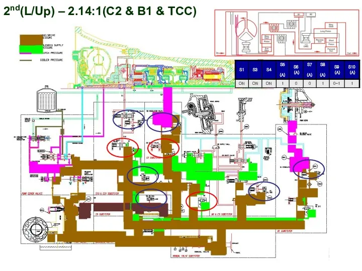
2nd(L/Up) – 2.14:1(C2 & B1 & TCC)
2nd(L/Up) – 2.14:1(C2 & B1 & TCC)
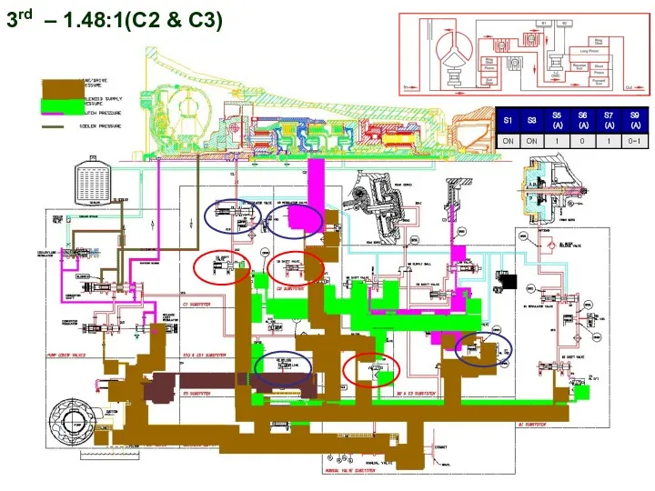
3rd – 1.48:1(C2 & C3)
3rd – 1.48:1(C2 & C3)
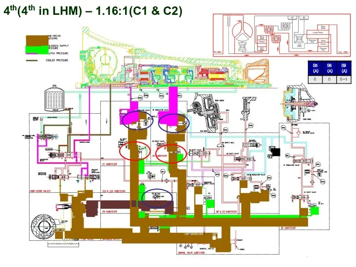
4th(4th in LHM) – 1.16:1(C1 & C2)
4th(4th in LHM) – 1.16:1(C1 & C2)
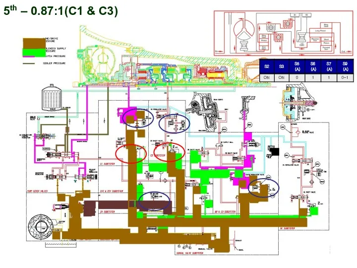
5th – 0.87:1(C1 & C3)
5th – 0.87:1(C1 & C3)
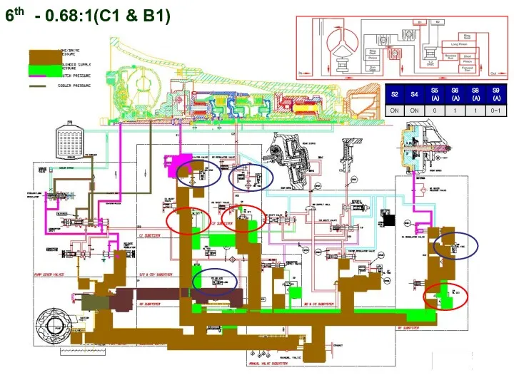
6th - 0.68:1(C1 & B1)
6th - 0.68:1(C1 & B1)
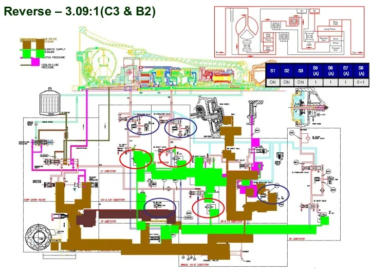
Reverse – 3.09:1(C3 & B2)
Reverse – 3.09:1(C3 & B2)
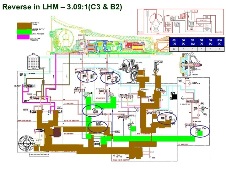
Reverse in LHM – 3.09:1(C3 & B2)
Reverse in LHM – 3.09:1(C3 & B2)
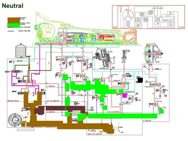
Neutral
Neutral
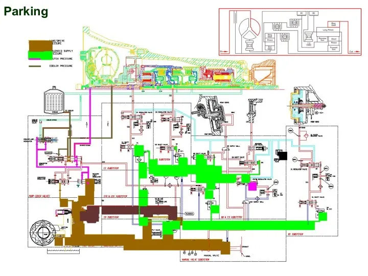
Parking
Parking
T
C
U
Diagnosis
CAN line
Sol 1
Sol 2
Sol 7
Sol 3
Sol 4
Sol 5(Variable)
Sol 6
Mode lamp
Lamp on
T
C
U
Diagnosis
CAN line
Sol 1
Sol 2
Sol 7
Sol 3
Sol 4
Sol 5(Variable)
Sol 6
Mode lamp
Lamp on
T
C
U
TCU Input & Output I (M74-DI Engine)
T
C
U
TCU Input & Output I (M74-DI Engine)
T
C
U
Engine torque demand
Engaged/Target gear
Lock up control
TGS lever position
Engine oil temp
E
C
U
W/Speed RR
H
E
C
U
W/Speed
T
C
U
Engine torque demand
Engaged/Target gear
Lock up control
TGS lever position
Engine oil temp
E
C
U
W/Speed RR
H
E
C
U
W/Speed
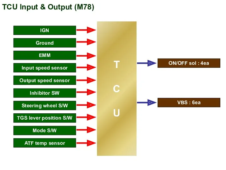
TCU Input & Output (M78)
T
C
U
IGN
Ground
EMM
Input speed sensor
Output speed sensor
ATF temp sensor
Inhibitor
TCU Input & Output (M78)
T
C
U
IGN
Ground
EMM
Input speed sensor
Output speed sensor
ATF temp sensor
Inhibitor
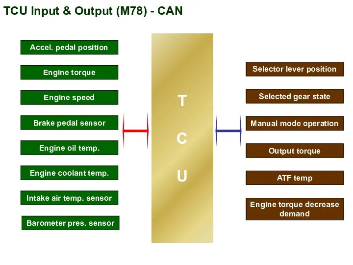
TCU Input & Output (M78) - CAN
Selector lever position
Selected gear state
Manual
TCU Input & Output (M78) - CAN
Selector lever position
Selected gear state
Manual
TCU input signal
■ EMM(Embedded Memory Module)
- Input speed sensor clustered
TCU input signal
■ EMM(Embedded Memory Module)
- Input speed sensor clustered
Input & Output signal wave form
CH1
2.0V
CH1
1.0V
2.0ms
ZOOM
HOLD
CH1
2.0V
CH1
1.0V
2.0ms
ZOOM
HOLD
CH1
2.0V
CH1
1.0V
2.0ms
ZOOM
HOLD
CH1
2.0V
CH1
1.0V
2.0ms
CH1
2.0V
CH1
1.0V
2.0ms
ZOOM
HOLD
Input shaft speed sensor
Output shaft speed
sensor
Input & Output signal wave form
CH1
2.0V
CH1
1.0V
2.0ms
ZOOM
HOLD
CH1
2.0V
CH1
1.0V
2.0ms
ZOOM
HOLD
CH1
2.0V
CH1
1.0V
2.0ms
ZOOM
HOLD
CH1
2.0V
CH1
1.0V
2.0ms
CH1
2.0V
CH1
1.0V
2.0ms
ZOOM
HOLD
Input shaft speed sensor
Output shaft speed
sensor
TCU input signal
■ Inhibitor switch
- TGS lever position detect
-
TCU input signal
■ Inhibitor switch
- TGS lever position detect
-
TCU input signal
■ Mode S/W
- DURA TGS lever
- Standard
TCU input signal
■ Mode S/W
- DURA TGS lever
- Standard
TCU output signal
■ ON/OFF sol. valve
- S1, S2, S3, S4
TCU output signal
■ ON/OFF sol. valve
- S1, S2, S3, S4
S1
S2
S3
S4
S5
S6
S7
Making gear shifting
-
-
Control shifting order & shifting
quality
Clutch regulator valve control
Front
S1
S2
S3
S4
S5
S6
S7
Making gear shifting
-
-
Control shifting order & shifting
quality
Clutch regulator valve control
Front
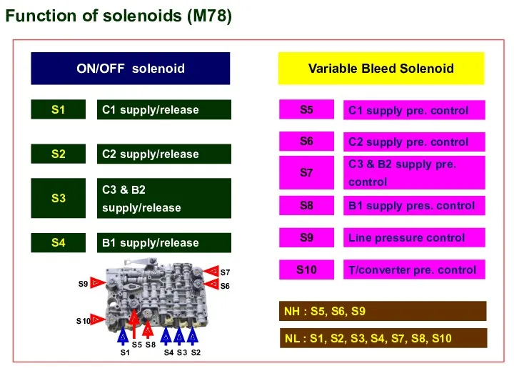
ON/OFF solenoid
Variable Bleed Solenoid
S1
S2
S3
S5
S6
C1 supply pre. control
C1 supply/release
S4
C2 supply/release
C3 & B2
ON/OFF solenoid
Variable Bleed Solenoid
S1
S2
S3
S5
S6
C1 supply pre. control
C1 supply/release
S4
C2 supply/release
C3 & B2
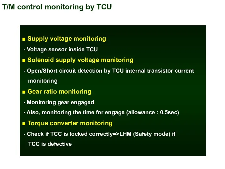
T/M control monitoring by TCU
■ Supply voltage monitoring
- Voltage sensor
T/M control monitoring by TCU
■ Supply voltage monitoring
- Voltage sensor
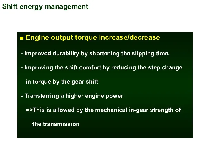
Shift energy management
■ Engine output torque increase/decrease
- Improved durability by
Shift energy management
■ Engine output torque increase/decrease
- Improved durability by
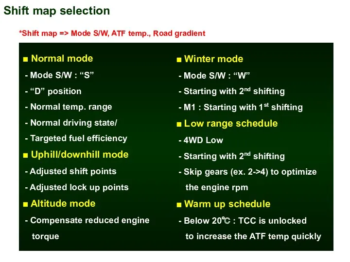
Shift map selection
■ Normal mode
- Mode S/W : “S”
Shift map selection
■ Normal mode
- Mode S/W : “S”
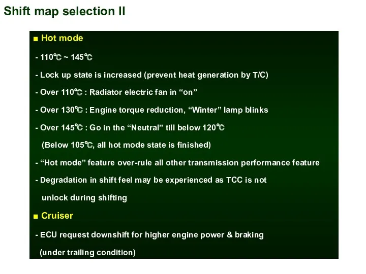
Shift map selection II
■ Hot mode
- 110℃ ~ 145℃
-
Shift map selection II
■ Hot mode
- 110℃ ~ 145℃
-
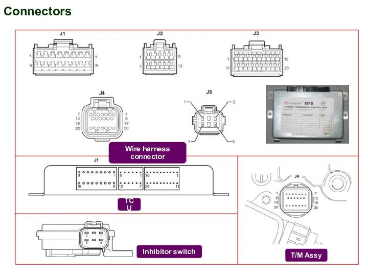
Connectors
Wire harness connector
TCU
T/M Assy
Inhibitor switch
Connectors
Wire harness connector
TCU
T/M Assy
Inhibitor switch
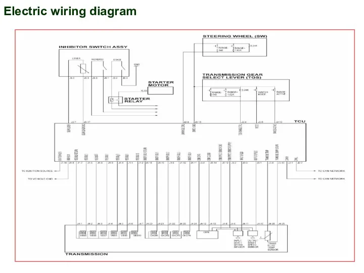
Electric wiring diagram
Electric wiring diagram
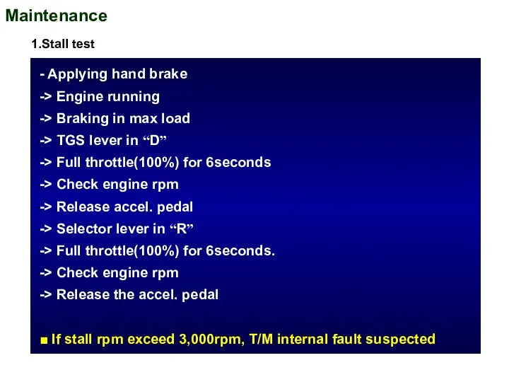
Maintenance
- Applying hand brake
-> Engine running
-> Braking
Maintenance
- Applying hand brake
-> Engine running
-> Braking
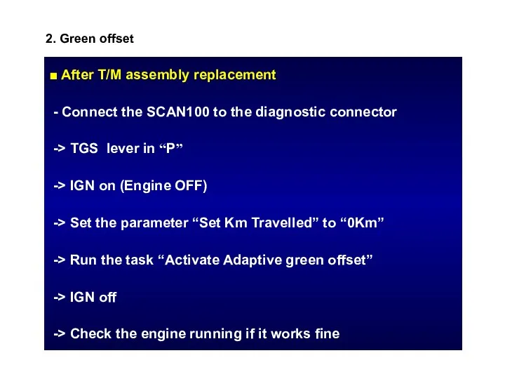
2. Green offset
■ After T/M assembly replacement
- Connect the SCAN100
2. Green offset
■ After T/M assembly replacement
- Connect the SCAN100
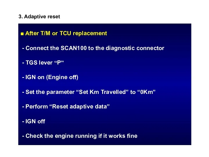
3. Adaptive reset
■ After T/M or TCU replacement
- Connect the
3. Adaptive reset
■ After T/M or TCU replacement
- Connect the
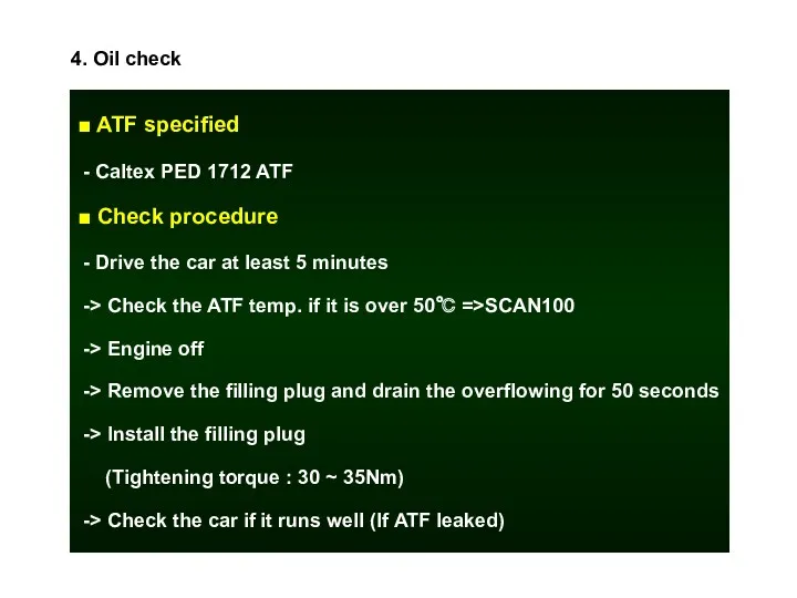
4. Oil check
■ ATF specified
- Caltex PED 1712 ATF
■ Check
4. Oil check
■ ATF specified
- Caltex PED 1712 ATF
■ Check
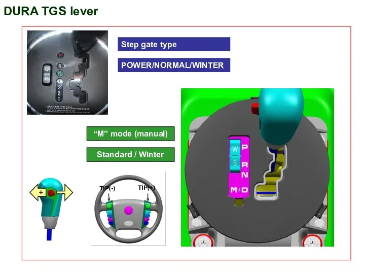
DURA TGS lever
TIP(-)
TIP(+)
Step gate type
POWER/NORMAL/WINTER
“M” mode (manual)
Standard / Winter
DURA TGS lever
TIP(-)
TIP(+)
Step gate type
POWER/NORMAL/WINTER
“M” mode (manual)
Standard / Winter
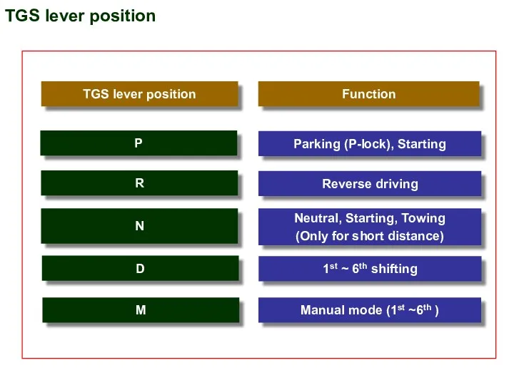
TGS lever position
Function
Parking (P-lock), Starting
Reverse driving
Neutral, Starting, Towing
(Only for short distance)
P
R
N
1st
TGS lever position
Function
Parking (P-lock), Starting
Reverse driving
Neutral, Starting, Towing
(Only for short distance)
P
R
N
1st
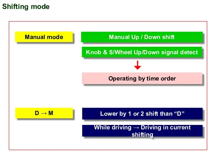
Shifting mode
Manual Up / Down shift
Knob & S/Wheel Up/Down signal detect
Manual
Shifting mode
Manual Up / Down shift
Knob & S/Wheel Up/Down signal detect
Manual
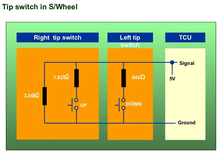
Tip switch in S/Wheel
3.24㏀
1.62㏀
845Ω
DOWN
UP
Signal
Ground
Right tip switch
Left tip switch
TCU
5V
Tip switch in S/Wheel
3.24㏀
1.62㏀
845Ω
DOWN
UP
Signal
Ground
Right tip switch
Left tip switch
TCU
5V
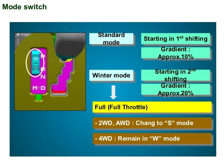
Mode switch
Standard mode
Winter mode
Starting in 1st shifting
Gradient : Approx.10%
Full (Full Throttle)
-
Mode switch
Standard mode
Winter mode
Starting in 1st shifting
Gradient : Approx.10%
Full (Full Throttle)
-
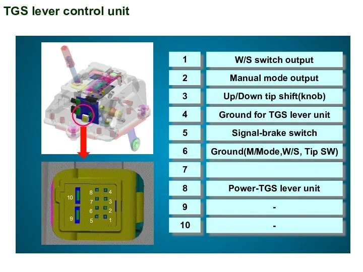
TGS lever control unit
1
2
3
4
5
6
7
8
9
10
W/S switch output
Manual mode output
Up/Down tip shift(knob)
Ground for
TGS lever control unit
1
2
3
4
5
6
7
8
9
10
W/S switch output
Manual mode output
Up/Down tip shift(knob)
Ground for
 Элементы машиноведения
 Литография
 Фрагменты урока на тему: Давление жидкостей и газов, Закон Архимеда
 Работа воздухораспределителя усл. № 483. Зарядка
 Механическая работа. Единицы работы. Мощность. Единицы мощности
 Методическая рекомендация внеклассного мероприятия Физическая лихорадка Диск
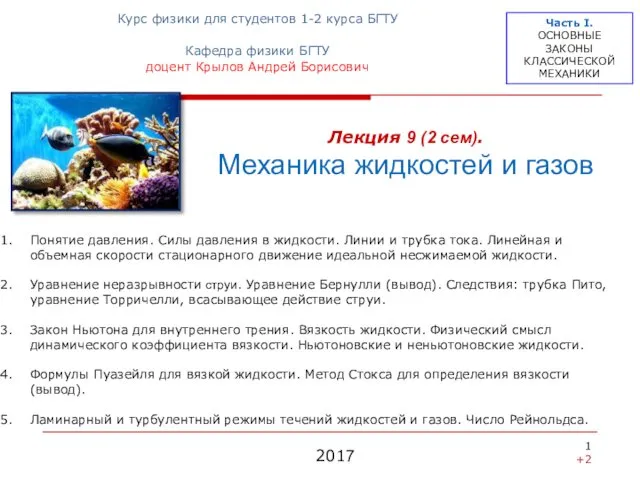 Механика жидкостей и газов. (Лекция 9)
 Дисперсия света. Цвета тел
 Начало космической эры и роль ученых нашей страны в изучении вселенной
 урок физики в 8 классе Мир сквозь очки
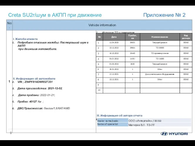 Creta SU2r/шум в АКПП при движение
 Магнит өрісі
 Проблемно-задачный подход обучения физике
 Закон всемирного тяготения
 Устройство электрических подстанций и составление их схем
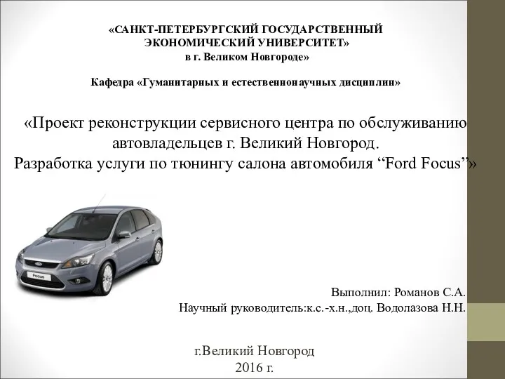 Проект реконструкции сервисного центра по обслуживанию автовладельцев г. Великий Новгород. Разработка услуги по тюнингу салона
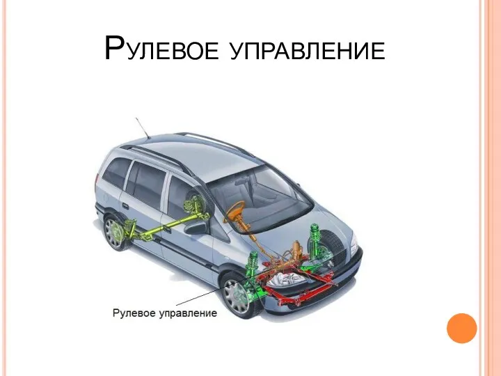 Рулевое управление
 Кран вспомогательного тормоза №254
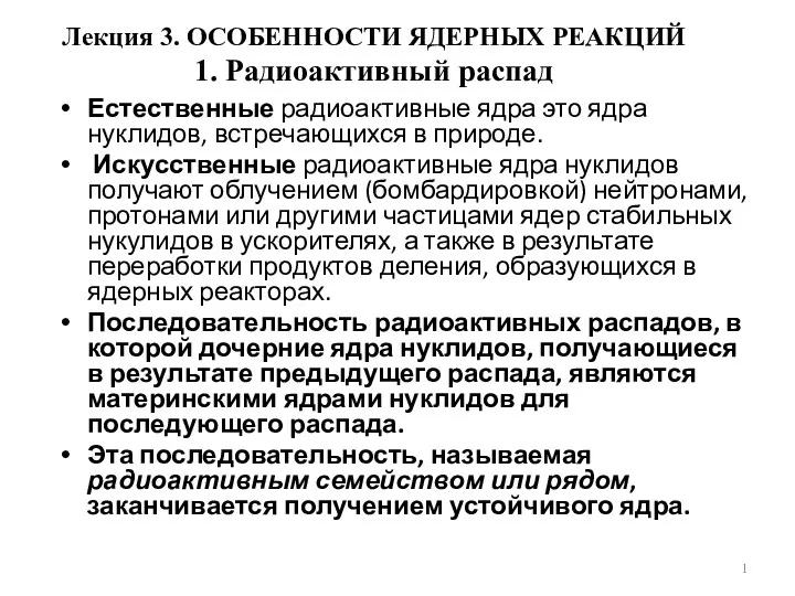 Особенности ядерных реакций
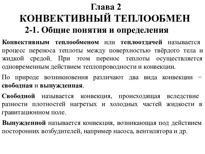 Конвективный теплообмен
 Проходимость автомобиля
 Газовые законы. Урок физики в 10 классе
 Ультразвук: источники и применение.
 История лампочки
 Ударно-тяговые устройства подвижного состава
 Курс Атомные реакторы и ядерная энергетика. Лекция 5. Формула четырех сомножителей
 Повторение за 8 класс
 Механические характеристики электродвигателей постоянного тока