- Computer Systems. (Unit 2)

Содержание
- 2. Two Antennas got married - the wedding was lousy, but the reception was outstanding THINK ABOUT
- 3. Define computer bridges Explain the function of BIOS Distinguish among various CMOS setup utility options Troubleshoot
- 4. BIOS AND CMOS
- 5. BIOS (BASIC INPUT OUTPUT SYSTEM) The BIOS contains instructions and setup for how your system should
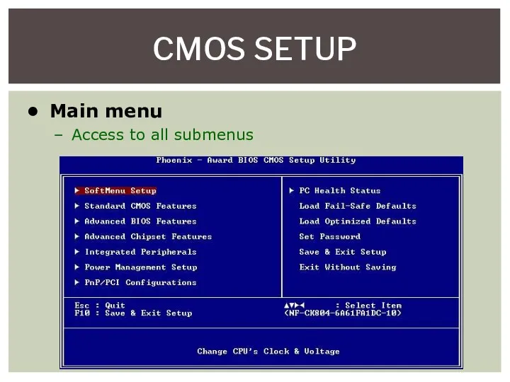
- 6. CMOS SETUP Main menu Access to all submenus
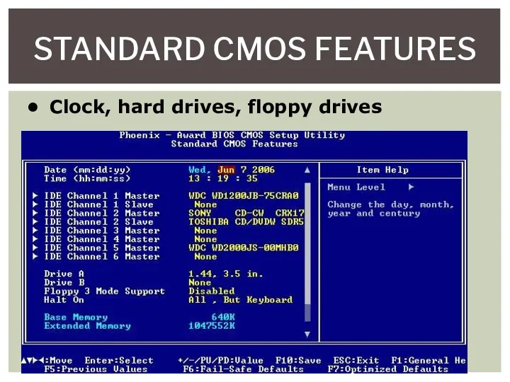
- 7. STANDARD CMOS FEATURES Clock, hard drives, floppy drives
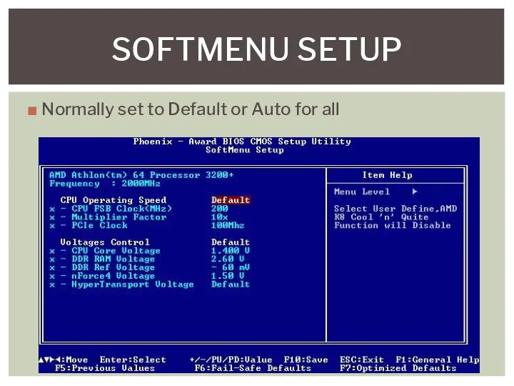
- 8. Normally set to Default or Auto for all SOFTMENU SETUP
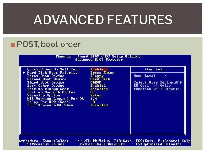
- 9. POST, boot order ADVANCED FEATURES
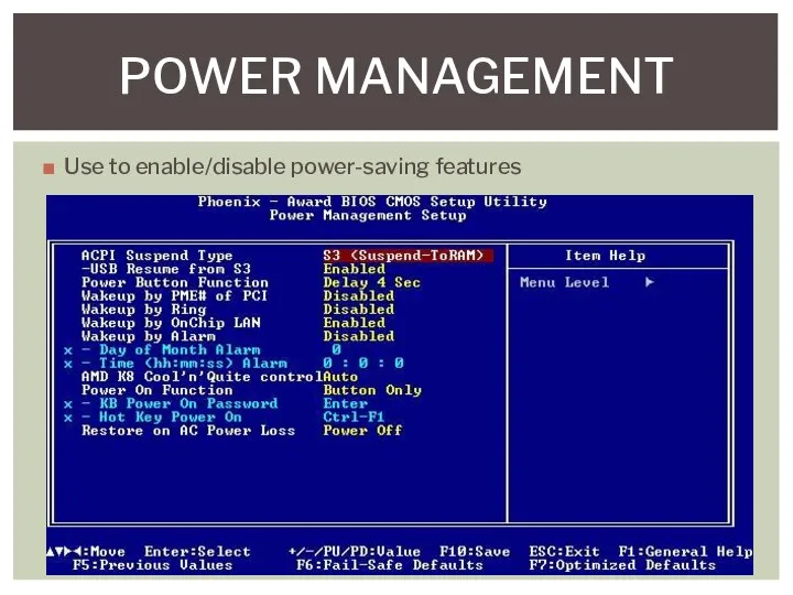
- 10. Use to enable/disable power-saving features POWER MANAGEMENT
- 11. Rarely need to manipulate on today’s PCs PNP/PCI
- 12. The power-on self test (POST) is a special program stored on the ROM chip Initiated when
- 13. If video is determined to be missing or faulty One long beep followed by three short
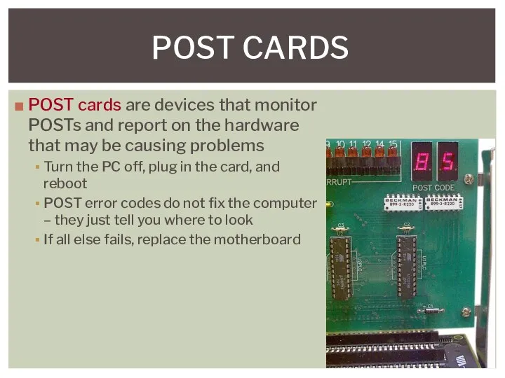
- 14. POST CARDS POST cards are devices that monitor POSTs and report on the hardware that may
- 15. UPDATING/FLASHING THE BIOS Flashing your BIOS to the latest release is crucial because it enhances your
- 16. To clear the CMOS settings, place the shunt on the CMOS jumper Resets to factory settings
- 17. Data flows through the computer Between CPU and RAM Between CPU and video Between CPU and
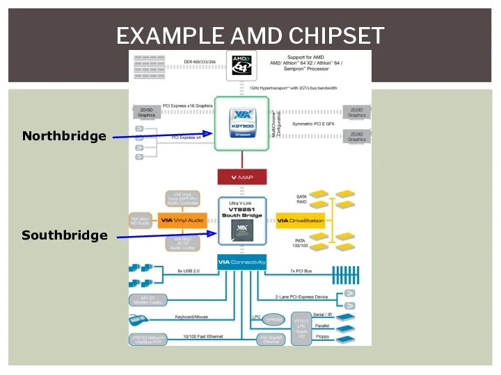
- 18. Northbridge Chip or chips that connect the CPU to video and/or memory Southbridge Handles all of
- 19. DATA FLOW Northbridge and Southbridge have connectivity with all devices Not the same in all systems
- 20. EXAMPLE AMD CHIPSET Northbridge Southbridge
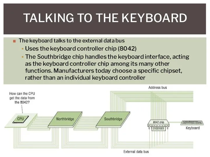
- 21. TALKING TO THE KEYBOARD The keyboard talks to the external data bus Uses the keyboard controller
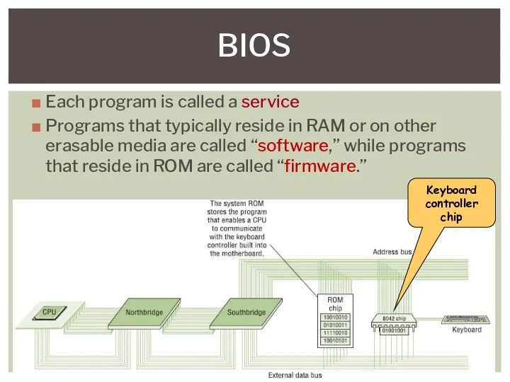
- 22. BIOS Each program is called a service Programs that typically reside in RAM or on other
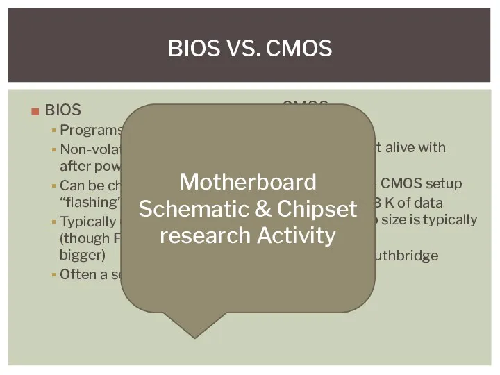
- 23. BIOS Programs Non-volatile (stays same after power off) Can be changed by “flashing” Typically 64 K
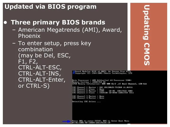
- 24. Updating CMOS Updated via BIOS program Three primary BIOS brands American Megatrends (AMI), Award, Phoenix To
- 25. CMOS (COMPLEMENTARY METAL OXIDE SEMICONDUCTOR) The CMOS is powered by a CMOS battery and contains your
- 26. LOSING CMOS SETTINGS Common errors CMOS configuration mismatch CMOS date/time not set No boot device available
- 27. A PSU converts the 115-volt alternating current (AC) supplied by an electrical outlet into direct current
- 28. Every PSU in use today is either an AT or an ATX The main difference is
- 29. 4 Pin Berg Connector Used to connect the PSU to small form factor devices, such as
- 30. A modular power supply unit, abbreviated MPS, is a type of PSU with cables to powered
- 31. ATX POWER SUPPLY PIN OUTS
- 32. A multimeter measures electrical properties such as AC or DC voltage, current, and resistance Electricians and
- 33. A digital multimeter has an LCD screen that gives a straight forward decimal read out, while
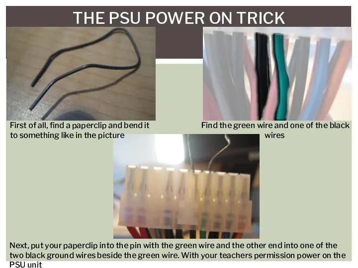
- 34. THE PSU POWER ON TRICK First of all, find a paperclip and bend it to something
- 36. Скачать презентацию

Two Antennas got married - the wedding was lousy, but the
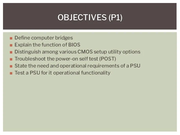
Define computer bridges
Explain the function of BIOS
Distinguish among various CMOS setup
Define computer bridges
Explain the function of BIOS
Distinguish among various CMOS setup
BIOS AND CMOS
BIOS AND CMOS
BIOS (BASIC INPUT OUTPUT SYSTEM)
The BIOS contains instructions and setup
BIOS (BASIC INPUT OUTPUT SYSTEM)
The BIOS contains instructions and setup
CMOS SETUP
Main menu
Access to all submenus
CMOS SETUP
Main menu
Access to all submenus
STANDARD CMOS FEATURES
Clock, hard drives, floppy drives
STANDARD CMOS FEATURES
Clock, hard drives, floppy drives
Normally set to Default or Auto for all
SOFTMENU SETUP
Normally set to Default or Auto for all
SOFTMENU SETUP
POST, boot order
ADVANCED FEATURES
POST, boot order
ADVANCED FEATURES
Use to enable/disable power-saving features
POWER MANAGEMENT
Use to enable/disable power-saving features
POWER MANAGEMENT
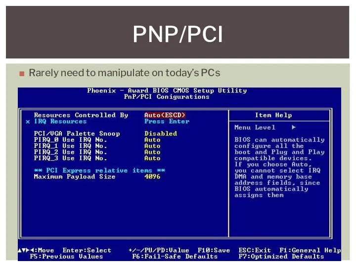
Rarely need to manipulate on today’s PCs
PNP/PCI
Rarely need to manipulate on today’s PCs
PNP/PCI

The power-on self test (POST) is a special program stored on
The power-on self test (POST) is a special program stored on
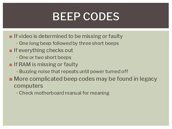
If video is determined to be missing or faulty
One long beep
If video is determined to be missing or faulty
One long beep
POST CARDS
POST cards are devices that monitor POSTs and report
POST CARDS
POST cards are devices that monitor POSTs and report
UPDATING/FLASHING THE BIOS
Flashing your BIOS to the latest release is crucial
UPDATING/FLASHING THE BIOS
Flashing your BIOS to the latest release is crucial
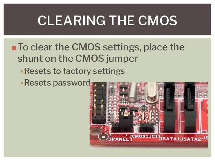
To clear the CMOS settings, place the shunt on the CMOS
To clear the CMOS settings, place the shunt on the CMOS
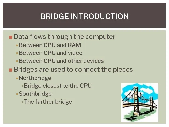
Data flows through the computer
Between CPU and RAM
Between CPU and video
Between
Data flows through the computer
Between CPU and RAM
Between CPU and video
Between
Northbridge
Chip or chips that connect the CPU to video and/or memory
Southbridge
Handles
Northbridge
Chip or chips that connect the CPU to video and/or memory
Southbridge
Handles
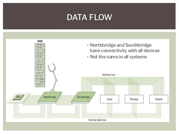
DATA FLOW
Northbridge and Southbridge
have connectivity with all devices
Not the same in
DATA FLOW
Northbridge and Southbridge
have connectivity with all devices
Not the same in
EXAMPLE AMD CHIPSET
Northbridge
Southbridge
EXAMPLE AMD CHIPSET
Northbridge
Southbridge
TALKING TO THE KEYBOARD
The keyboard talks to the external data bus
TALKING TO THE KEYBOARD
The keyboard talks to the external data bus
BIOS
Each program is called a service
Programs that typically reside in RAM
BIOS
Each program is called a service
Programs that typically reside in RAM
BIOS
Programs
Non-volatile (stays same after power off)
Can be changed by “flashing”
Typically 64
BIOS
Programs
Non-volatile (stays same after power off)
Can be changed by “flashing”
Typically 64
Updating CMOS
Updated via BIOS program
Three primary BIOS brands
American Megatrends (AMI),
Updating CMOS
Updated via BIOS program
Three primary BIOS brands
American Megatrends (AMI),
CMOS (COMPLEMENTARY METAL OXIDE SEMICONDUCTOR)
The CMOS is powered by a CMOS
CMOS (COMPLEMENTARY METAL OXIDE SEMICONDUCTOR)
The CMOS is powered by a CMOS
LOSING CMOS SETTINGS
Common errors
CMOS configuration mismatch
CMOS date/time not set
No boot device
LOSING CMOS SETTINGS
Common errors
CMOS configuration mismatch
CMOS date/time not set
No boot device

A PSU converts the 115-volt alternating current (AC) supplied by an
A PSU converts the 115-volt alternating current (AC) supplied by an
Every PSU in use today is either an AT or an
Every PSU in use today is either an AT or an
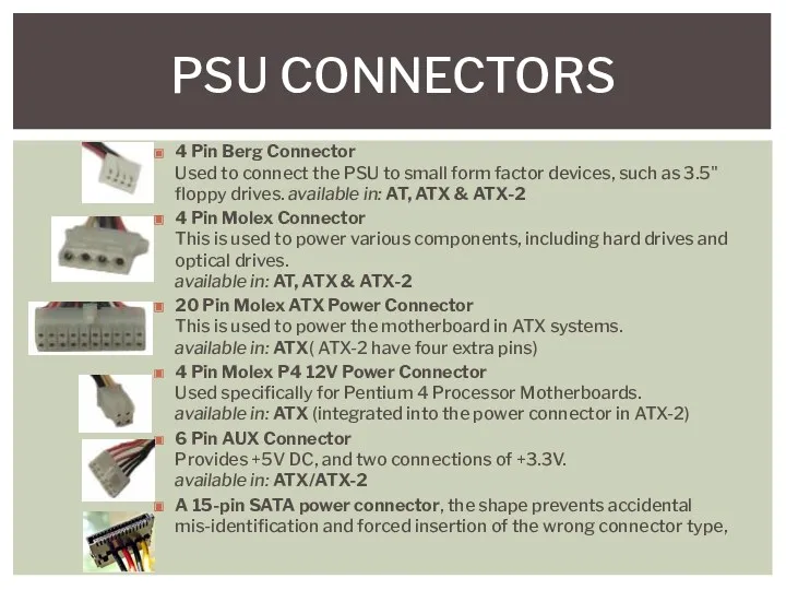
4 Pin Berg Connector
Used to connect the PSU to small form
4 Pin Berg Connector Used to connect the PSU to small form
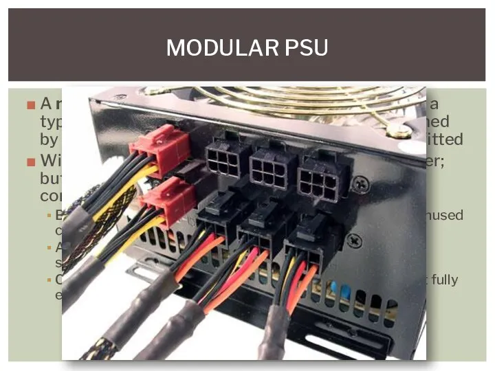
A modular power supply unit, abbreviated MPS, is a type of
A modular power supply unit, abbreviated MPS, is a type of
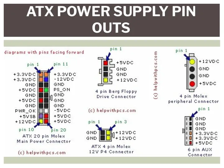
ATX POWER SUPPLY PIN OUTS
ATX POWER SUPPLY PIN OUTS
A multimeter measures electrical properties such as AC or DC voltage,
A multimeter measures electrical properties such as AC or DC voltage,
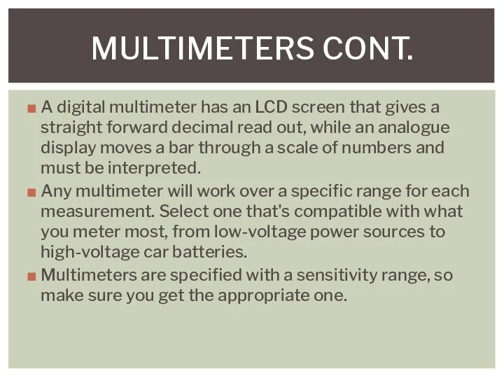
A digital multimeter has an LCD screen that gives a straight
A digital multimeter has an LCD screen that gives a straight
THE PSU POWER ON TRICK
First of all, find a paperclip and
THE PSU POWER ON TRICK
First of all, find a paperclip and
 Множественное наследование. Лекция 18
 Справочные издания
 Представления (VIEW). Лабораторная работа 7
 Системы счисления. Представление чисел в компьютере
 Эволюция операционных систем
 Дерево целей - как метод исследования
 Этапы развития вычислительной техники в период 60-х – 70-х
 Основные понятия криптографической защиты. Симметричные алгоритмы шифрования
 Стандартные программы Windows 7. (Лекция 7)
 Основные принципы работы в программе Cisco Packet Tracer
 Архитектура крупных систем информационного обеспечения
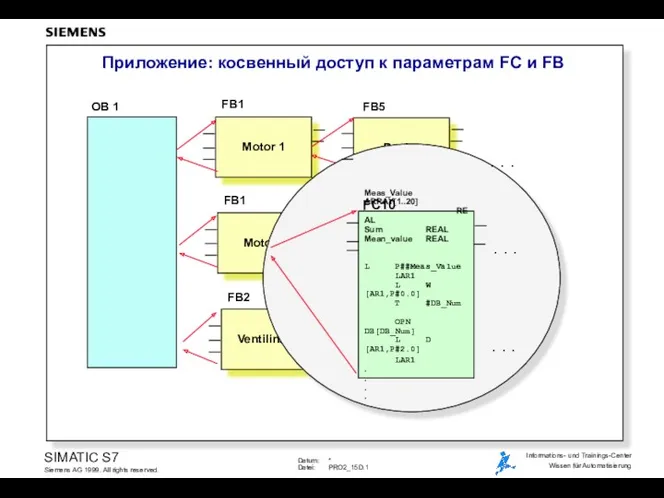 Приложение: косвенный доступ к параметрам FC и FB
 презентация к уроку Глобальная компьютерная сеть Интернет
 Оптимізація топології гетерогенної комп’ютерної мережі навчального закладу
 Средства коммуникационной техники. Средства и системы телефонной связи
 Влияние современных СМИ на молодёжь
 Розвиток інформатики в Україні
 Урок по теме Устройства компьютера
 Основные понятия и задачи моделирования процессов и систем
 Структура компьютера. Понятие вычислительной системы
 Основы гидродинамического моделирования
 Классификация программного обеспечения
 Кибербезопасность для младших школьников
 Язык PHP
 Введение в SDH
 Библиотеки PID_Regulators и PID_Reg2. Программные ПИД-регуляторы (на примере пакета CoDeSys)
 Как найти информацию о стажировках
 Понятие сетевой модели. Сетевая модель OSI. (Тема 8)