- CPU How It Works

Содержание
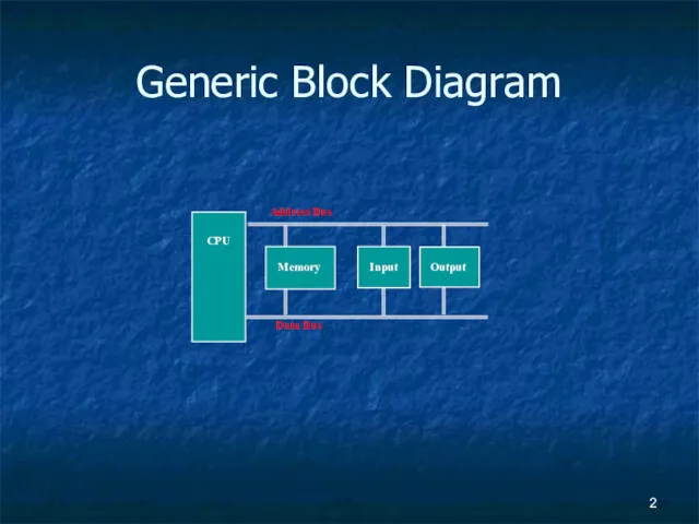
- 2. Generic Block Diagram CPU Memory Input Output Address Bus Data Bus
- 3. Hardware
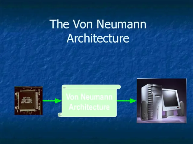
- 4. The Von Neumann Architecture Von Neumann Architecture
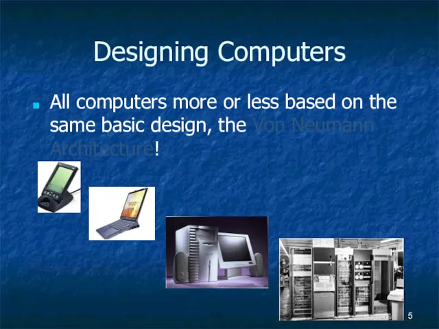
- 5. Designing Computers All computers more or less based on the same basic design, the Von Neumann
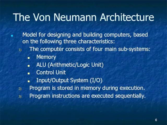
- 6. The Von Neumann Architecture Model for designing and building computers, based on the following three characteristics:
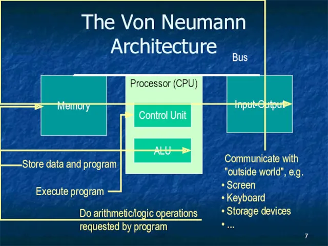
- 7. The Von Neumann Architecture Memory Processor (CPU) Input-Output Control Unit ALU Bus
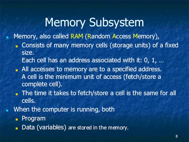
- 8. Memory Subsystem Memory, also called RAM (Random Access Memory), Consists of many memory cells (storage units)
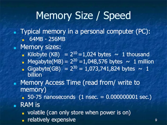
- 9. Memory Size / Speed Typical memory in a personal computer (PC): 64MB - 256MB Memory sizes:
- 10. Operations on Memory Fetch (address): Fetch a copy of the content of memory cell with the
- 11. Structure of the Memory Subsystem Fetch(address) Load address into MAR. Decode the address in MAR. Copy
- 12. Input/Output Subsystem Handles devices that allow the computer system to: Communicate and interact with the outside
- 13. I/O Controllers Speed of I/O devices is slow compared to RAM RAM ~ 50 nsec. Hard-Drive
- 14. I/O controller Structure of the I/O Subsystem I/O Buffer Control/Logic I/O device Data from/to memory Interrupt
- 15. The ALU Subsystem The ALU (Arithmetic/Logic Unit) performs mathematical operations (+, -, x, /, …) logic
- 16. Structure of the ALU Registers: Very fast local memory cells, that store operands of operations and
- 17. The Control Unit Program is stored in memory as machine language instructions, in binary The task
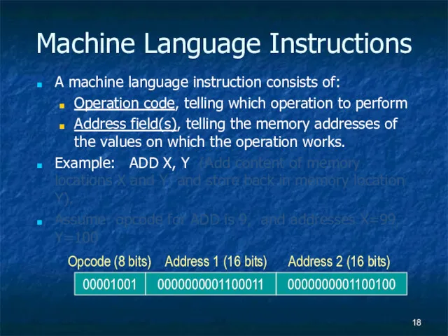
- 18. Machine Language Instructions A machine language instruction consists of: Operation code, telling which operation to perform
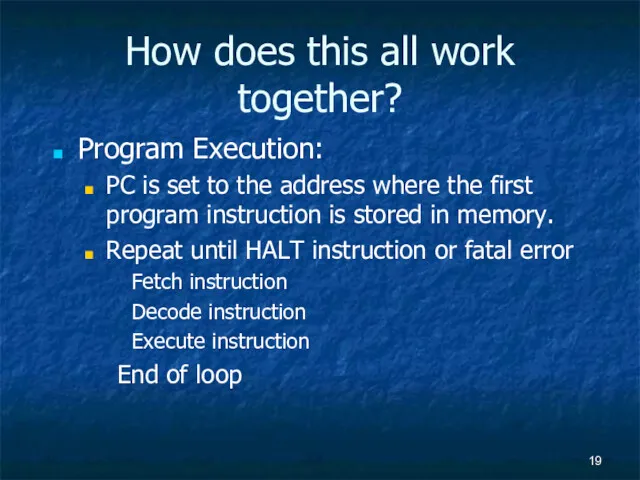
- 19. How does this all work together? Program Execution: PC is set to the address where the
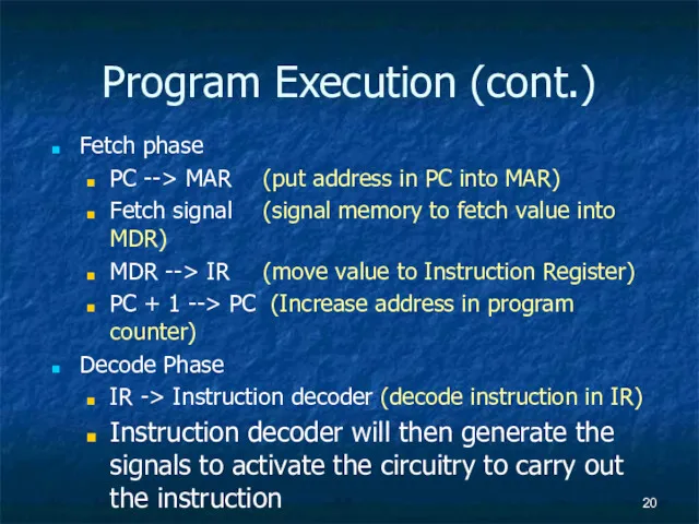
- 20. Program Execution (cont.) Fetch phase PC --> MAR (put address in PC into MAR) Fetch signal
- 22. Скачать презентацию
Generic Block Diagram
CPU
Memory
Input
Output
Address Bus
Data Bus
Generic Block Diagram
CPU
Memory
Input
Output
Address Bus
Data Bus
Hardware
Hardware
The Von Neumann Architecture
Von Neumann
Architecture
The Von Neumann Architecture
Von Neumann
Architecture
Designing Computers
All computers more or less based on the same basic design, the
Designing Computers
All computers more or less based on the same basic design, the
The Von Neumann Architecture
Model for designing and building computers, based on the following
The Von Neumann Architecture
Model for designing and building computers, based on the following
The Von Neumann Architecture
Memory
Processor (CPU)
Input-Output
Control Unit
ALU
Bus
The Von Neumann Architecture
Memory
Processor (CPU)
Input-Output
Control Unit
ALU
Bus
Memory Subsystem
Memory, also called RAM (Random Access Memory),
Consists of many memory cells
Memory Subsystem
Memory, also called RAM (Random Access Memory),
Consists of many memory cells
Memory Size / Speed
Typical memory in a personal computer (PC):
64MB - 256MB
Memory
Memory Size / Speed
Typical memory in a personal computer (PC):
64MB - 256MB
Memory
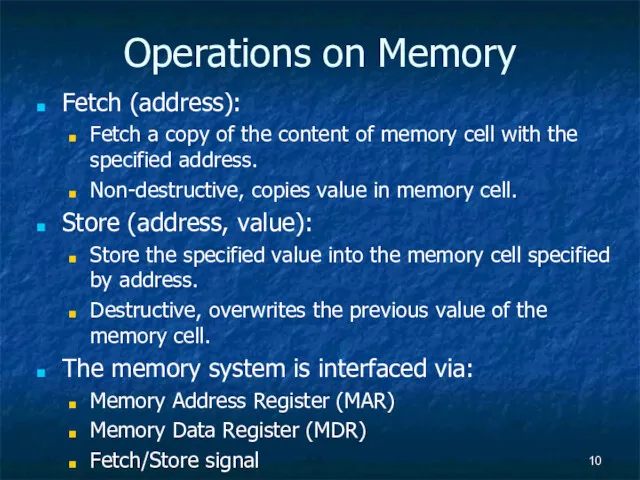
Operations on Memory
Fetch (address):
Fetch a copy of the content of memory cell
Operations on Memory
Fetch (address):
Fetch a copy of the content of memory cell
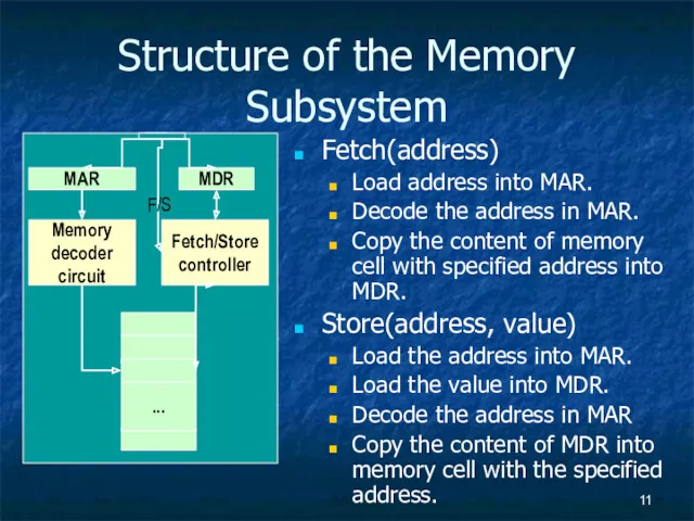
Structure of the Memory Subsystem
Fetch(address)
Load address into MAR.
Decode the address in MAR.
Copy the
Structure of the Memory Subsystem
Fetch(address)
Load address into MAR.
Decode the address in MAR.
Copy the
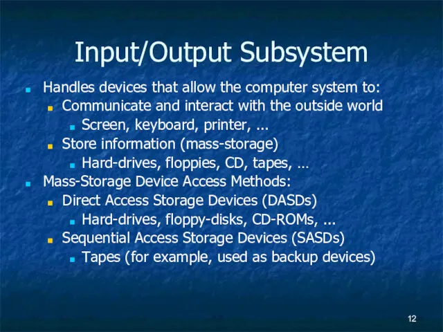
Input/Output Subsystem
Handles devices that allow the computer system to:
Communicate and interact with the
Input/Output Subsystem
Handles devices that allow the computer system to:
Communicate and interact with the
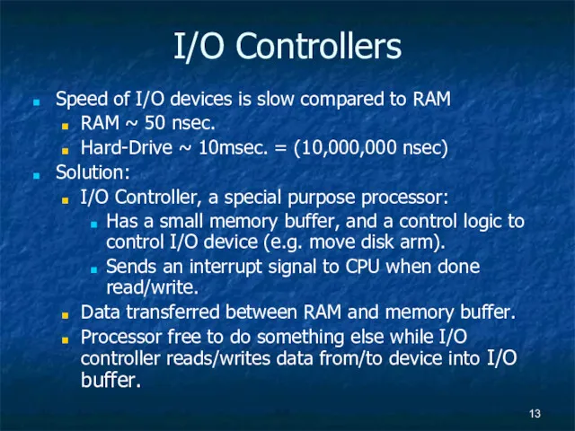
I/O Controllers
Speed of I/O devices is slow compared to RAM
RAM ~ 50 nsec.
Hard-Drive
I/O Controllers
Speed of I/O devices is slow compared to RAM
RAM ~ 50 nsec.
Hard-Drive
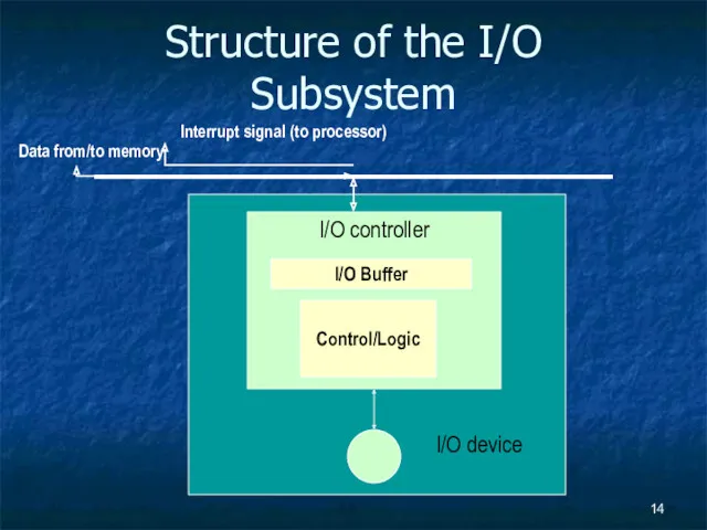
I/O controller
Structure of the I/O Subsystem
I/O Buffer
Control/Logic
I/O device
Data from/to memory
Interrupt signal (to processor)
I/O controller
Structure of the I/O Subsystem
I/O Buffer
Control/Logic
I/O device
Data from/to memory
Interrupt signal (to processor)
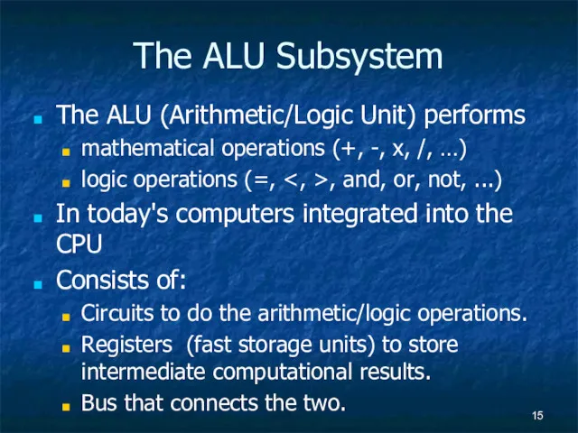
The ALU Subsystem
The ALU (Arithmetic/Logic Unit) performs
mathematical operations (+, -, x, /, …)
logic
The ALU Subsystem
The ALU (Arithmetic/Logic Unit) performs
mathematical operations (+, -, x, /, …)
logic
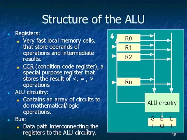
Structure of the ALU
Registers:
Very fast local memory cells, that store operands of operations
Structure of the ALU
Registers:
Very fast local memory cells, that store operands of operations
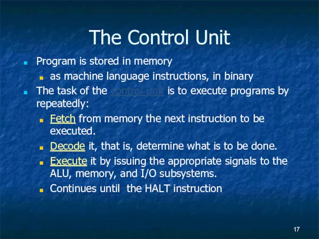
The Control Unit
Program is stored in memory
as machine language instructions, in binary
The
The Control Unit
Program is stored in memory
as machine language instructions, in binary
The
Machine Language Instructions
A machine language instruction consists of:
Operation code, telling which operation to
Machine Language Instructions
A machine language instruction consists of:
Operation code, telling which operation to
How does this all work together?
Program Execution:
PC is set to the address where
How does this all work together?
Program Execution:
PC is set to the address where
Program Execution (cont.)
Fetch phase
PC --> MAR (put address in PC into MAR)
Fetch signal (signal memory
Program Execution (cont.)
Fetch phase
PC --> MAR (put address in PC into MAR)
Fetch signal (signal memory
 Язык программирование Pascal ABC
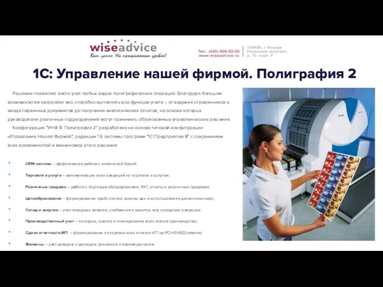 1С: Управление нашей фирмой. Полиграфия 2
 Персональный компьютер компьютер как унивесальное устройство для работы с информацией
 Всемирная паутина - WWW
 Базы и банки данных. Раздел 2. Концептуальное моделирование. ER-диаграмма
 Вектор Айлиффа( Ilife)
 JS and CSS Bundling and Minification
 Построение сети на основе концепции NGN
 Задание. КИМы по ЕГЭ-2012
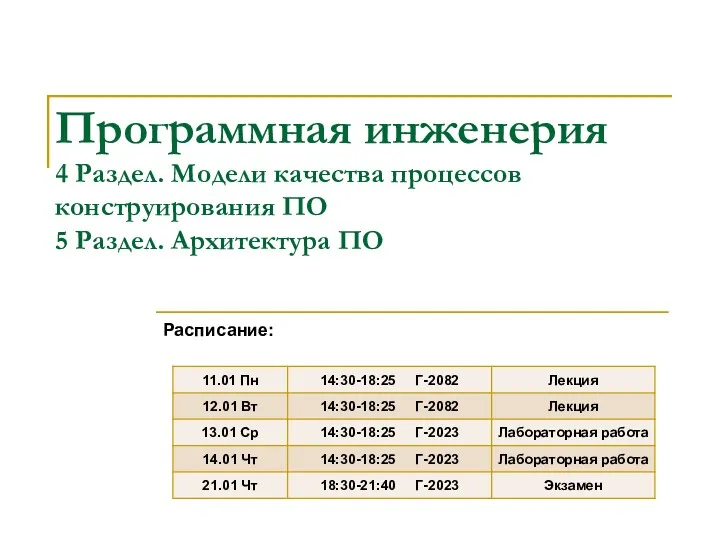 Модели качества процессов конструирования ПО
 Запуск Snort в качестве IDS
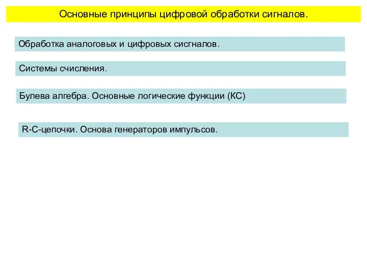 Основные принципы цифровой обработки сигналов
 Битва Клубов. Финал
 Java Troubleshooting and Diagnostic
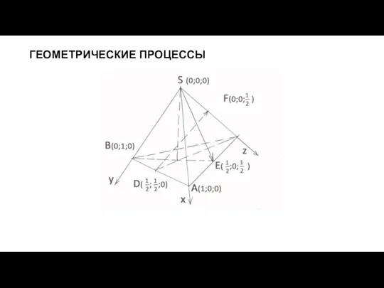 Геометрические процессы. Основные виды алгоритмов
 Технологии разработки программного обеспечения. Функциональная спецификация
 Программирование на языке Python
 Бинарный урок по физике и информатике на тему: Законы Ньютона. Создание теста на заданную тему. 10-й класс
 Создание презентации в PowerPoint
 Коммутация каналов, коммутация пакетов. Постоянная и динамическая коммутация сети
 Функции журналистики в обществе
 План урока по теме Интернет. Поиск информации в компьютерных сетях
 Использование однострочных функций для получения требуемых выходных данных
 Платформы для дистанционного обучения
 Модули в Python
 Компьютерная графика. Графический редактор. Устройства ввода графической информации
 Що таке інтернет
 Журналы-юбиляры 2018 года