- Development and Simulation

Содержание
- 2. Contents Overview System Component: EU System Component: DM System Component: XBAR System Component: Streaming Unit System
- 3. Contents “Design by Simulation” Strategy Hardware Considerations Structure of the Simulator Software Tests and Examples ToDo’s
- 4. OVERVIEW
- 5. Objectives Develop a framework and building blocks for the application specific vector processor, make simulation software.
- 6. Objectives Framework should provide unified approach for the development of the functional components: Execution Units (EU)
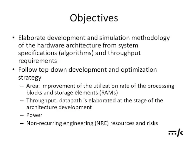
- 7. Objectives Elaborate development and simulation methodology of the hardware architecture from system specifications (algorithms) and throughput
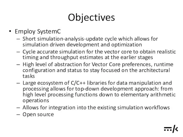
- 8. Objectives Employ SystemC Short simulation-analysis-update cycle which allows for simulation driven development and optimization Cycle accurate
- 9. Block Diagram
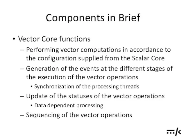
- 10. Components in Brief Vector Core functions Performing vector computations in accordance to the configuration supplied from
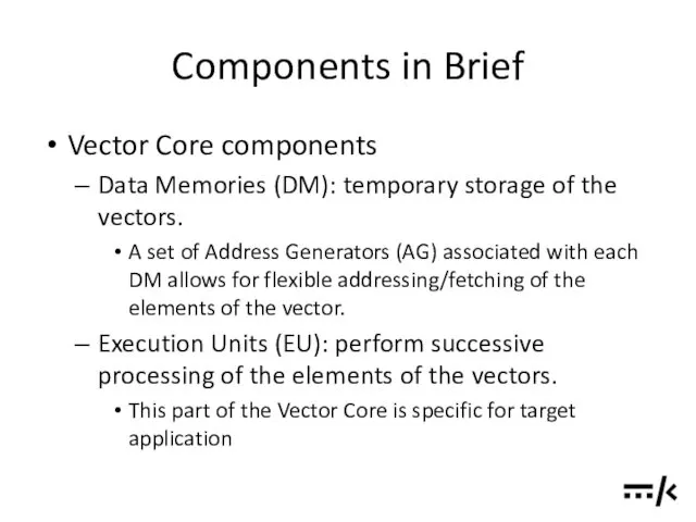
- 11. Components in Brief Vector Core components Data Memories (DM): temporary storage of the vectors. A set
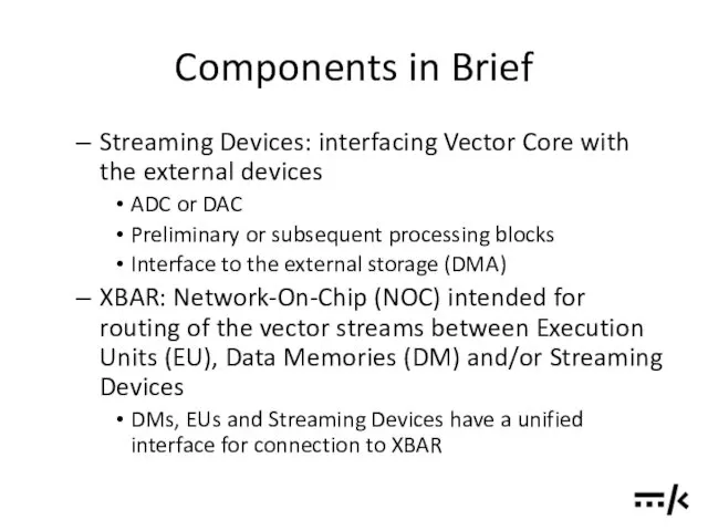
- 12. Components in Brief Streaming Devices: interfacing Vector Core with the external devices ADC or DAC Preliminary
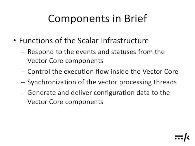
- 13. Components in Brief Functions of the Scalar Infrastructure Respond to the events and statuses from the
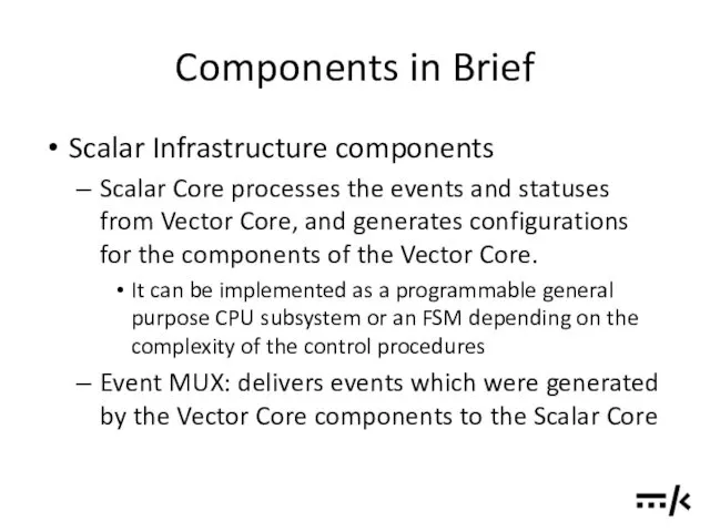
- 14. Components in Brief Scalar Infrastructure components Scalar Core processes the events and statuses from Vector Core,
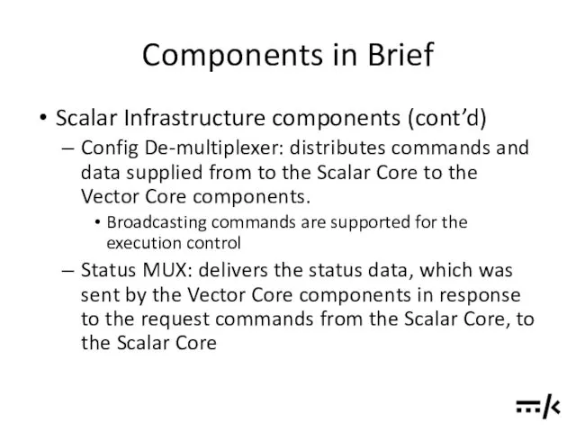
- 15. Components in Brief Scalar Infrastructure components (cont’d) Config De-multiplexer: distributes commands and data supplied from to
- 16. Outline of the development strategy Decompose the processing algorithm down to the level of functional blocks
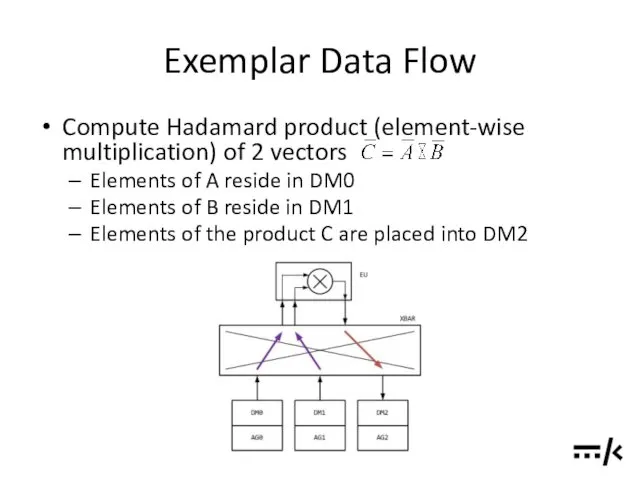
- 17. Exemplar Data Flow Compute Hadamard product (element-wise multiplication) of 2 vectors Elements of A reside in
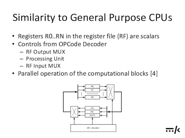
- 18. Similarity to General Purpose CPUs Registers R0..RN in the register file (RF) are scalars Controls from
- 19. VALID-READY Channel Main rule: Data is transferred at the active clock edge when both VALID and
- 20. VALID-READY Channel VALID before READY handshake READY before VALID handshake VALID with READY handshake *Refer to
- 21. VALID-READY Channel SOURCE retains the state of VALID and DATA signals until the transaction is acknowledged
- 22. VALID-READY Channel At the DM/EU interface DATA signal which is transferred in 1 clock cycle contains
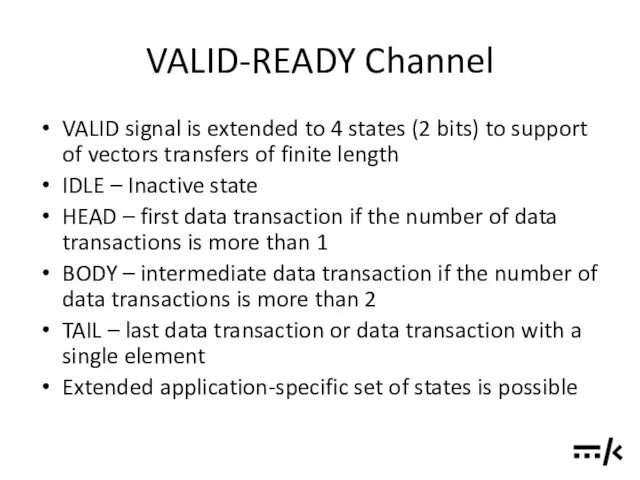
- 23. VALID-READY Channel VALID signal is extended to 4 states (2 bits) to support of vectors transfers
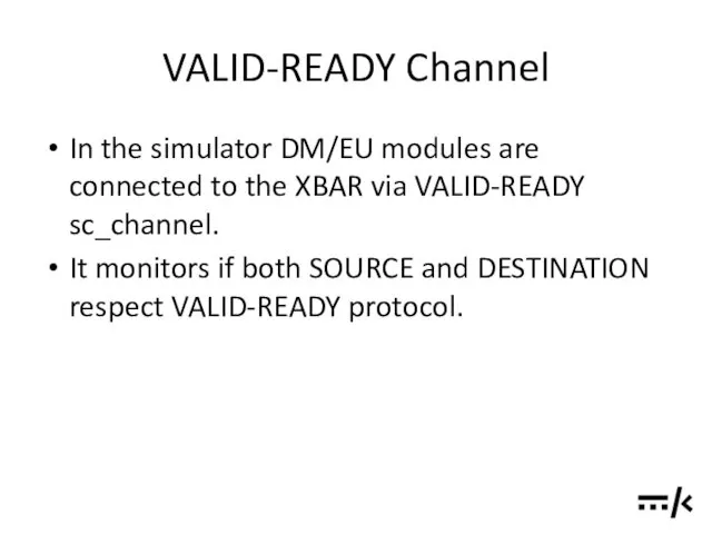
- 24. VALID-READY Channel In the simulator DM/EU modules are connected to the XBAR via VALID-READY sc_channel. It
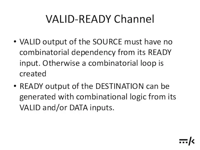
- 25. VALID-READY Channel VALID output of the SOURCE must have no combinatorial dependency from its READY input.
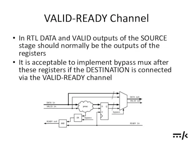
- 26. VALID-READY Channel In RTL DATA and VALID outputs of the SOURCE stage should normally be the
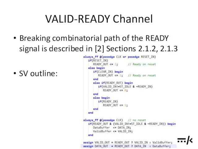
- 27. VALID-READY Channel Breaking combinatorial path of the READY signal is described in [2] Sections 2.1.2, 2.1.3
- 28. VALID-READY Channel When merging streams, a processing stage should rely on all the upstream SOURCES to
- 29. VALID-READY Channel To constrain combinational paths through the XBAR, both input and output signals of VALID,
- 30. SYSTEM COMPONENT: EU
- 31. SYSTEM COMPONENT: DM
- 32. SYSTEM COMPONENT: XBAR
- 33. SYSTEM COMPONENT: STREAMING UNIT
- 34. SYSTEM COMPONENT: SCALAR INFRASTRUCTURE
- 35. PROGRAM EXECUTION
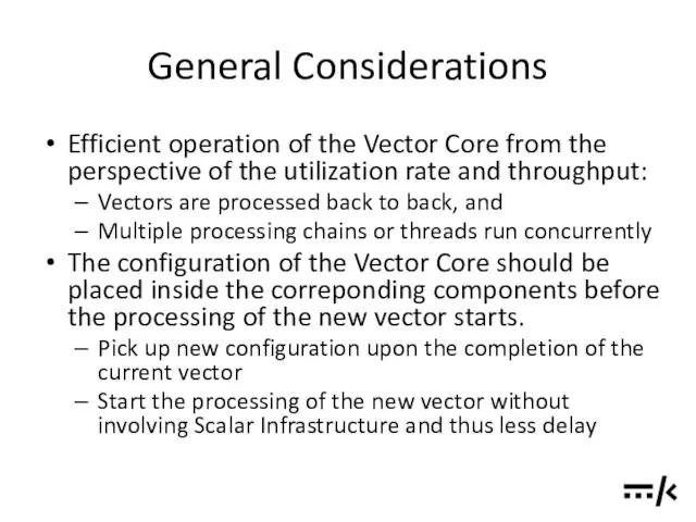
- 36. General Considerations Efficient operation of the Vector Core from the perspective of the utilization rate and
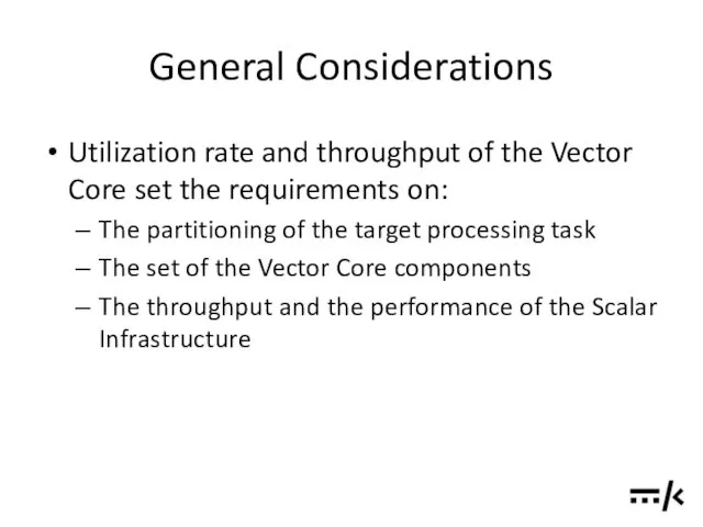
- 37. General Considerations Utilization rate and throughput of the Vector Core set the requirements on: The partitioning
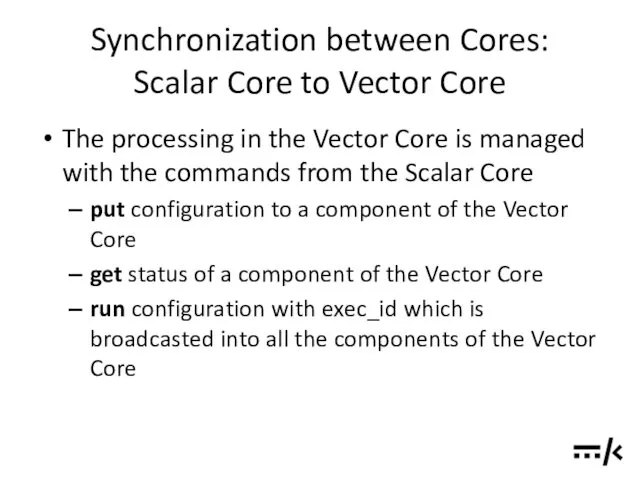
- 38. Synchronization between Cores: Scalar Core to Vector Core The processing in the Vector Core is managed
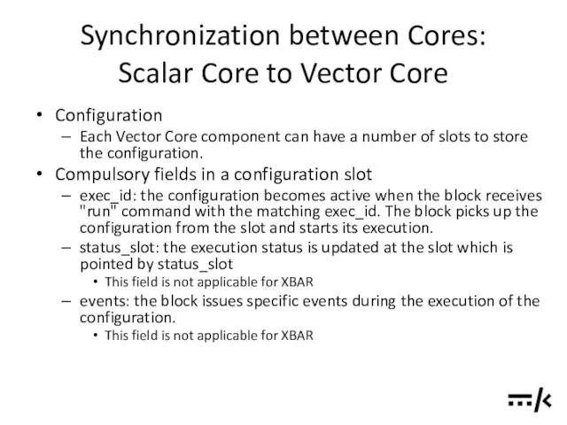
- 39. Synchronization between Cores: Scalar Core to Vector Core Configuration Each Vector Core component can have a
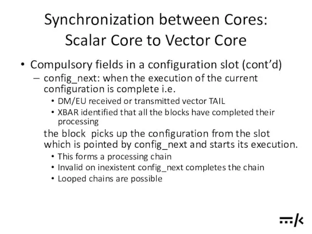
- 40. Synchronization between Cores: Scalar Core to Vector Core Compulsory fields in a configuration slot (cont’d) config_next:
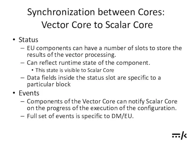
- 41. Synchronization between Cores: Vector Core to Scalar Core Status EU components can have a number of
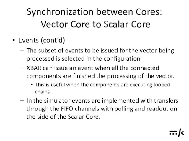
- 42. Synchronization between Cores: Vector Core to Scalar Core Events (cont’d) The subset of events to be
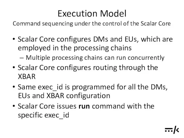
- 43. Execution Model Command sequencing under the control of the Scalar Core Scalar Core configures DMs and
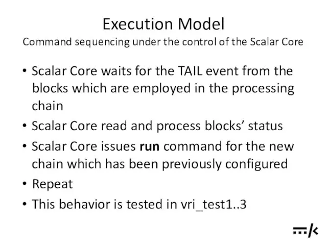
- 44. Execution Model Command sequencing under the control of the Scalar Core Scalar Core waits for the
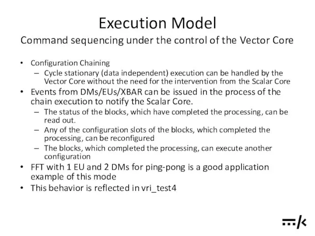
- 45. Execution Model Command sequencing under the control of the Vector Core Configuration Chaining Cycle stationary (data
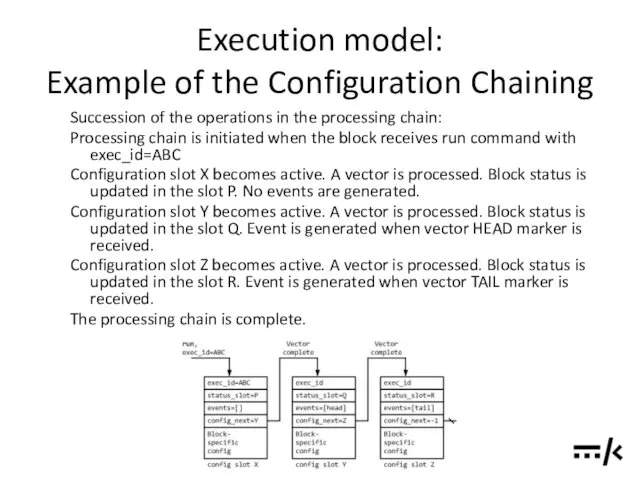
- 46. Execution model: Example of the Configuration Chaining Succession of the operations in the processing chain: Processing
- 47. Execution Model Deferred Execution Deferred Execution allows writing configuration and issuing run command to DMs, EUs
- 48. Execution Model Deferred Execution XBAR If XBAR receives run command for a configuration which connects DMs/EUs
- 49. Execution Model Data Exchange and Data Dependent Execution Components of the Vector Core can exchange small
- 50. Execution Model Data Exchange and Data Dependent Execution Exemplar task: frequency offset estimation in one chain
- 51. “DESIGN BY SIMULATION” STRATEGY
- 52. HARDWARE CONSIDERATIONS
- 53. STRUCTURE OF THE SIMULATOR SOFTWARE
- 54. TESTS AND EXAMPLES
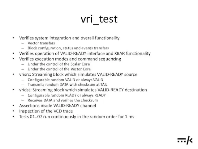
- 55. vri_test Verifies system integration and overall functionality Vector transfers Block configuration, status and events transfers Verifies
- 56. vri_test Clean make EXAMPLE=basic/vri_test clean Build make EXAMPLE=basic/vri_test all Run ./build/Release/out/simsimd Inspect the result: In gtkwave
- 57. vri_test / test01 Verifies basic operation Scalar core configures vector core components src1->dst1, src2->dst2 Scalar core
- 58. vri_test / test02 Verifies operation of the “always ready” destination Scalar core configures vector core components
- 59. vri_test / test03 Verifies data multicasting Scalar core configures vector core components src1->dst1, dst2. dst1 set
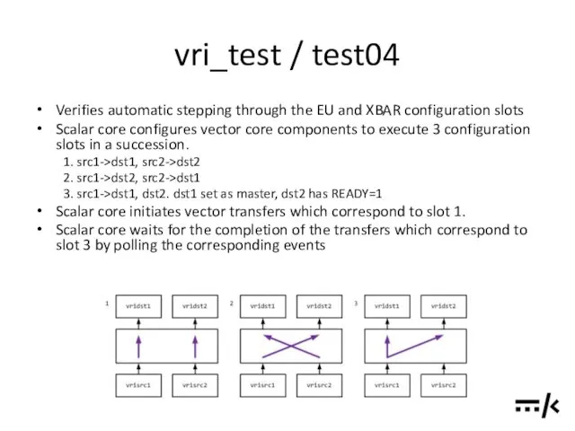
- 60. vri_test / test04 Verifies automatic stepping through the EU and XBAR configuration slots Scalar core configures
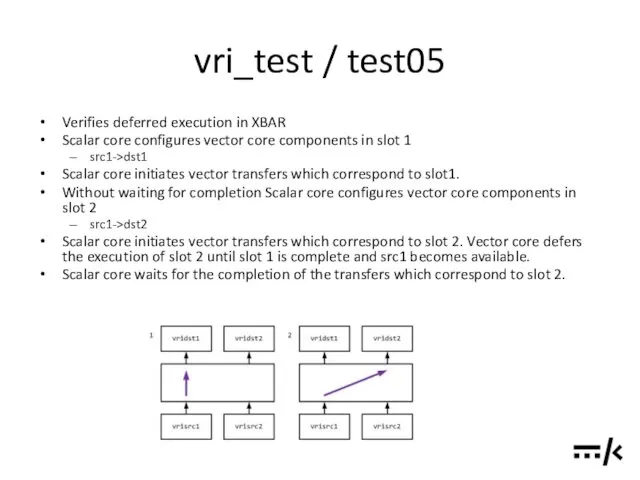
- 61. vri_test / test05 Verifies deferred execution in XBAR Scalar core configures vector core components in slot
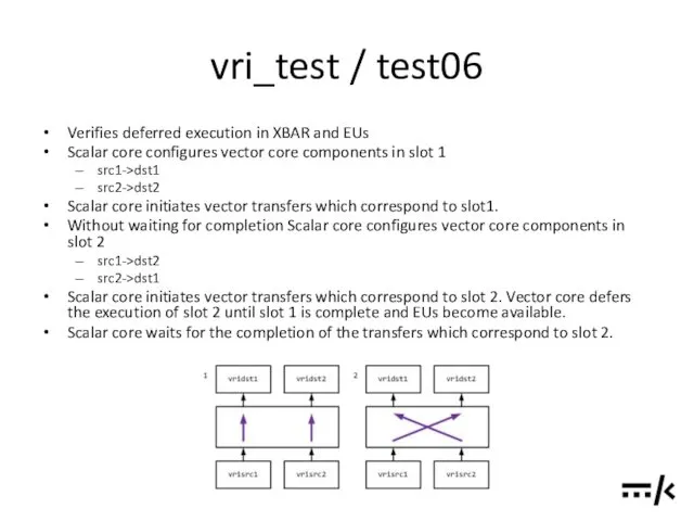
- 62. vri_test / test06 Verifies deferred execution in XBAR and EUs Scalar core configures vector core components
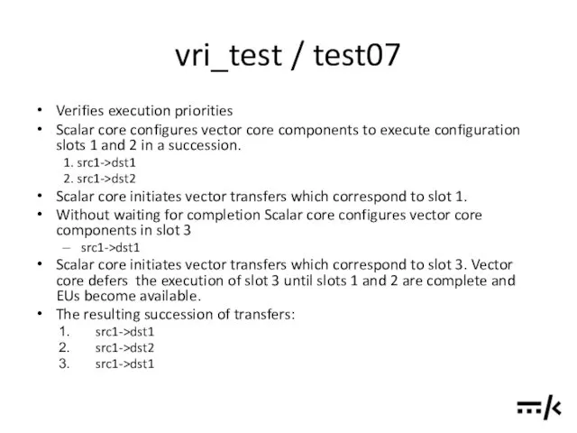
- 63. vri_test / test07 Verifies execution priorities Scalar core configures vector core components to execute configuration slots
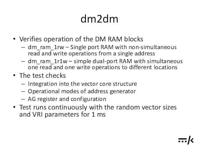
- 64. dm2dm Verifies operation of the DM RAM blocks dm_ram_1rw – Single port RAM with non-simultaneous read
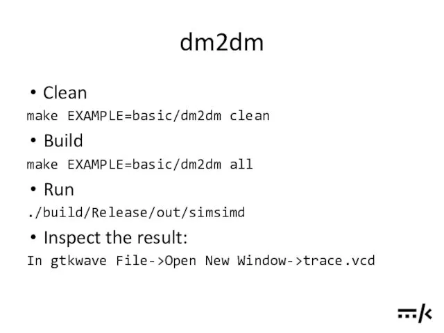
- 65. dm2dm Clean make EXAMPLE=basic/dm2dm clean Build make EXAMPLE=basic/dm2dm all Run ./build/Release/out/simsimd Inspect the result: In gtkwave
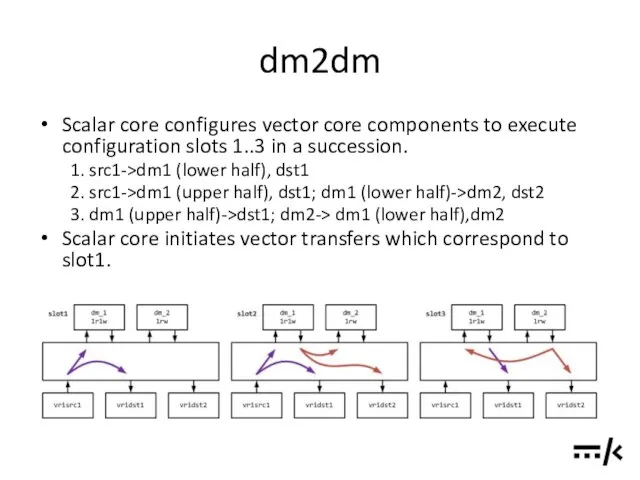
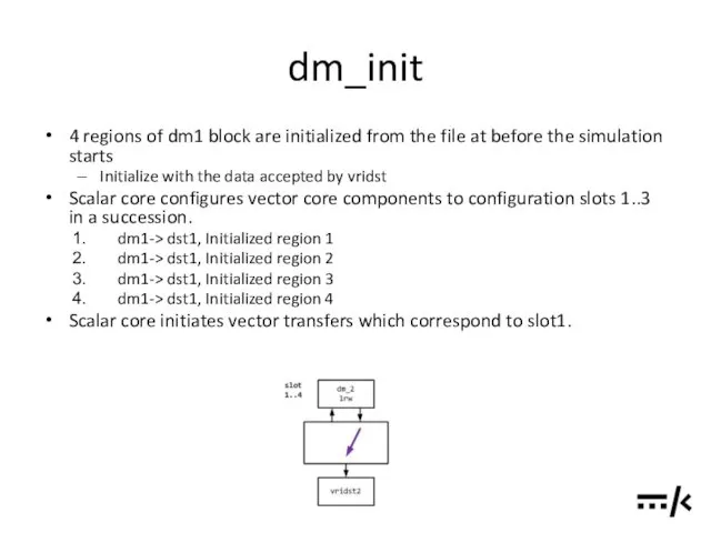
- 66. dm2dm Scalar core configures vector core components to execute configuration slots 1..3 in a succession. 1.
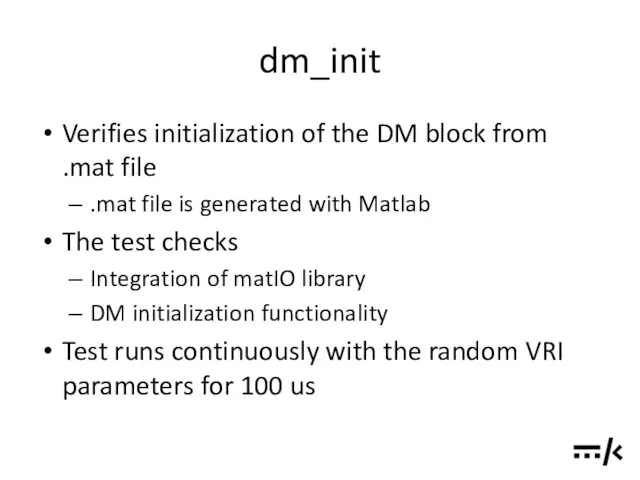
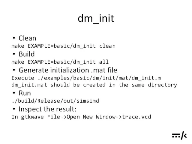
- 67. dm_init Verifies initialization of the DM block from .mat file .mat file is generated with Matlab
- 68. dm_init Clean make EXAMPLE=basic/dm_init clean Build make EXAMPLE=basic/dm_init all Generate initialization .mat file Execute ./examples/basic/dm/init/mat/dm_init.m dm_init.mat
- 69. dm_init 4 regions of dm1 block are initialized from the file at before the simulation starts
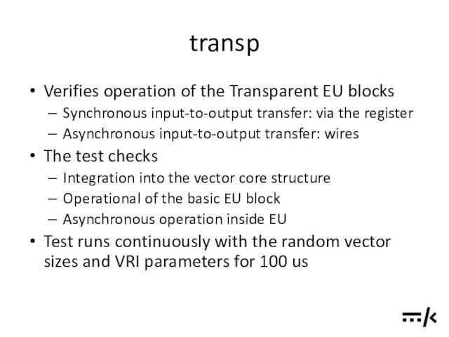
- 70. transp Verifies operation of the Transparent EU blocks Synchronous input-to-output transfer: via the register Asynchronous input-to-output
- 71. transp Clean make EXAMPLE=basic/transp clean Build make EXAMPLE=basic/transp all Run ./build/Release/out/simsimd Inspect the result: In gtkwave
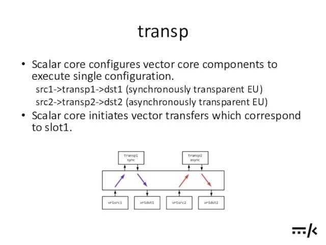
- 72. transp Scalar core configures vector core components to execute single configuration. src1->transp1->dst1 (synchronously transparent EU) src2->transp2->dst2
- 73. TODO’S AND PLANS
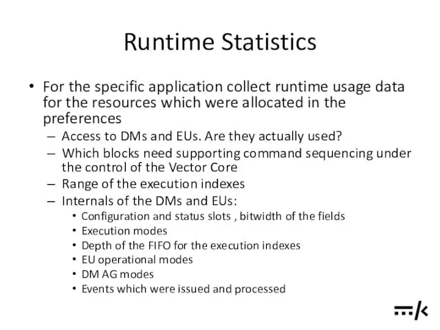
- 74. Runtime Statistics For the specific application collect runtime usage data for the resources which were allocated
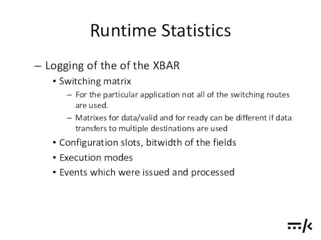
- 75. Runtime Statistics Logging of the of the XBAR Switching matrix For the particular application not all
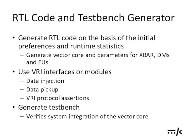
- 76. RTL Code and Testbench Generator Generate RTL code on the basis of the initial preferences and
- 77. Common Pool of Address Generators for DMs Additional cross-bar switch (AG -> 4way DMs) can make
- 78. Debug Interface for the Vector Core Debug Interface for the Vector Core
- 79. Data Dump Data Dump
- 80. FXP FXP
- 81. REFERENCES
- 82. Source Code and Documentation https://github.com/timurkelin/simsimd
- 83. Books, Papers and Presentations [1] Bridging dream and reality: Programmable baseband processors for software-defined radio, D.Liu,
- 84. Standards and Datasheets [3] AMBA 4 AXI4-Stream Protocol Specification, Version: 1.0, (c) 2010 ARM [4] SHARC
- 86. Скачать презентацию
Contents
Overview
System Component: EU
System Component: DM
System Component: XBAR
System Component: Streaming Unit
System
Contents
Overview
System Component: EU
System Component: DM
System Component: XBAR
System Component: Streaming Unit
System
Contents
“Design by Simulation” Strategy
Hardware Considerations
Structure of the Simulator Software
Tests and Examples
ToDo’s
Contents
“Design by Simulation” Strategy
Hardware Considerations
Structure of the Simulator Software
Tests and Examples
ToDo’s

OVERVIEW
OVERVIEW
Objectives
Develop a framework and building blocks for the application specific vector
Objectives
Develop a framework and building blocks for the application specific vector
Objectives
Framework should provide unified approach for the development of the functional
Objectives
Framework should provide unified approach for the development of the functional
Objectives
Elaborate development and simulation methodology of the hardware architecture from system
Objectives
Elaborate development and simulation methodology of the hardware architecture from system
Objectives
Employ SystemC
Short simulation-analysis-update cycle which allows for simulation driven development and
Objectives
Employ SystemC
Short simulation-analysis-update cycle which allows for simulation driven development and
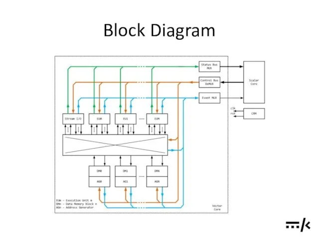
Block Diagram
Block Diagram
Components in Brief
Vector Core functions
Performing vector computations in accordance to the
Components in Brief
Vector Core functions
Performing vector computations in accordance to the
Components in Brief
Vector Core components
Data Memories (DM): temporary storage of
Components in Brief
Vector Core components
Data Memories (DM): temporary storage of
Components in Brief
Streaming Devices: interfacing Vector Core with the external devices
ADC
Components in Brief
Streaming Devices: interfacing Vector Core with the external devices
ADC
Components in Brief
Functions of the Scalar Infrastructure
Respond to the events and
Components in Brief
Functions of the Scalar Infrastructure
Respond to the events and
Components in Brief
Scalar Infrastructure components
Scalar Core processes the events and statuses
Components in Brief
Scalar Infrastructure components
Scalar Core processes the events and statuses
Components in Brief
Scalar Infrastructure components (cont’d)
Config De-multiplexer: distributes commands and data
Components in Brief
Scalar Infrastructure components (cont’d)
Config De-multiplexer: distributes commands and data
Outline of the development strategy
Decompose the processing algorithm down to the
Outline of the development strategy
Decompose the processing algorithm down to the
Exemplar Data Flow
Compute Hadamard product (element-wise multiplication) of 2 vectors
Elements of
Exemplar Data Flow
Compute Hadamard product (element-wise multiplication) of 2 vectors
Elements of
Similarity to General Purpose CPUs
Registers R0..RN in the register file (RF)
Similarity to General Purpose CPUs
Registers R0..RN in the register file (RF)
VALID-READY Channel
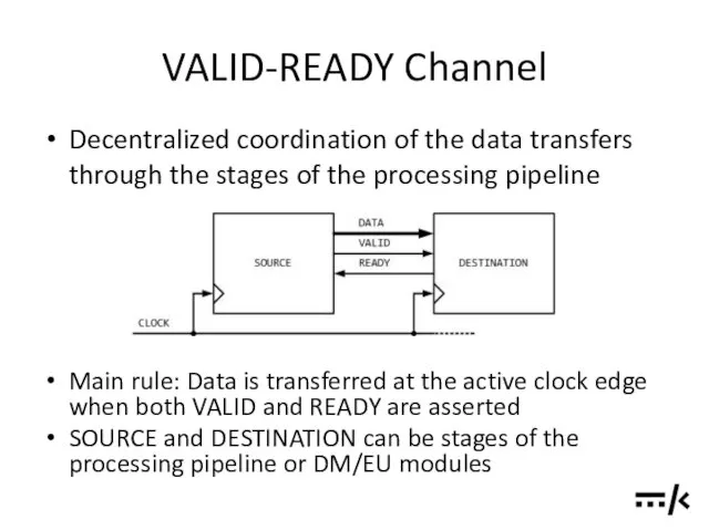
Main rule: Data is transferred at the active clock edge
VALID-READY Channel
Main rule: Data is transferred at the active clock edge
VALID-READY Channel
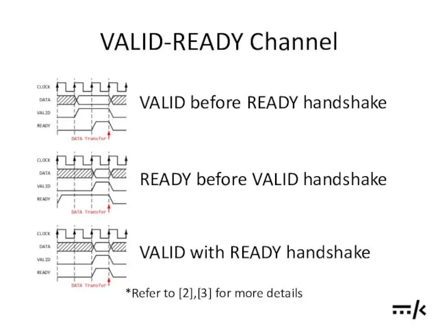
VALID before READY handshake
READY before VALID handshake
VALID with READY handshake
*Refer
VALID-READY Channel
VALID before READY handshake
READY before VALID handshake
VALID with READY handshake
*Refer
VALID-READY Channel
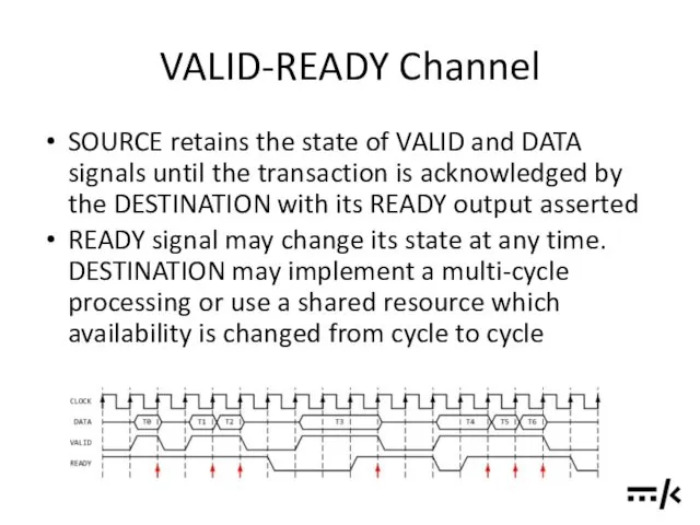
SOURCE retains the state of VALID and DATA signals until
VALID-READY Channel
SOURCE retains the state of VALID and DATA signals until
VALID-READY Channel
At the DM/EU interface DATA signal which is transferred in
VALID-READY Channel
At the DM/EU interface DATA signal which is transferred in
VALID-READY Channel
VALID signal is extended to 4 states (2 bits) to
VALID-READY Channel
VALID signal is extended to 4 states (2 bits) to
VALID-READY Channel
In the simulator DM/EU modules are connected to the XBAR
VALID-READY Channel
In the simulator DM/EU modules are connected to the XBAR
VALID-READY Channel
VALID output of the SOURCE must have no combinatorial dependency
VALID-READY Channel
VALID output of the SOURCE must have no combinatorial dependency
VALID-READY Channel
In RTL DATA and VALID outputs of the SOURCE stage
VALID-READY Channel
In RTL DATA and VALID outputs of the SOURCE stage
VALID-READY Channel
Breaking combinatorial path of the READY signal is described in
VALID-READY Channel
Breaking combinatorial path of the READY signal is described in
VALID-READY Channel
When merging streams, a processing stage should rely on all
VALID-READY Channel
When merging streams, a processing stage should rely on all
VALID-READY Channel
To constrain combinational paths through the XBAR, both input and
VALID-READY Channel
To constrain combinational paths through the XBAR, both input and
SYSTEM COMPONENT: EU
SYSTEM COMPONENT: EU
SYSTEM COMPONENT: DM
SYSTEM COMPONENT: DM
SYSTEM COMPONENT: XBAR
SYSTEM COMPONENT: XBAR
SYSTEM COMPONENT:
STREAMING UNIT
SYSTEM COMPONENT:
STREAMING UNIT
SYSTEM COMPONENT:
SCALAR INFRASTRUCTURE
SYSTEM COMPONENT:
SCALAR INFRASTRUCTURE
PROGRAM EXECUTION
PROGRAM EXECUTION
General Considerations
Efficient operation of the Vector Core from the perspective of
General Considerations
Efficient operation of the Vector Core from the perspective of
General Considerations
Utilization rate and throughput of the Vector Core set the
General Considerations
Utilization rate and throughput of the Vector Core set the
Synchronization between Cores:
Scalar Core to Vector Core
The processing in the Vector
Synchronization between Cores:
Scalar Core to Vector Core
The processing in the Vector
Synchronization between Cores:
Scalar Core to Vector Core
Configuration
Each Vector Core component can
Synchronization between Cores:
Scalar Core to Vector Core
Configuration
Each Vector Core component can
Synchronization between Cores:
Scalar Core to Vector Core
Compulsory fields in a configuration
Synchronization between Cores:
Scalar Core to Vector Core
Compulsory fields in a configuration
Synchronization between Cores:
Vector Core to Scalar Core
Status
EU components can have
Synchronization between Cores:
Vector Core to Scalar Core
Status
EU components can have
Synchronization between Cores:
Vector Core to Scalar Core
Events (cont’d)
The subset of
Synchronization between Cores:
Vector Core to Scalar Core
Events (cont’d)
The subset of
Execution Model
Command sequencing under the control of the Scalar Core
Scalar
Execution Model
Command sequencing under the control of the Scalar Core
Scalar
Execution Model
Command sequencing under the control of the Scalar Core
Scalar
Execution Model
Command sequencing under the control of the Scalar Core
Scalar
Execution Model
Command sequencing under the control of the Vector Core
Configuration
Execution Model
Command sequencing under the control of the Vector Core
Configuration
Execution model:
Example of the Configuration Chaining
Succession of the operations in
Execution model:
Example of the Configuration Chaining
Succession of the operations in
Execution Model
Deferred Execution
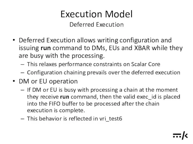
Deferred Execution allows writing configuration and issuing run
Execution Model
Deferred Execution
Deferred Execution allows writing configuration and issuing run
Execution Model
Deferred Execution
XBAR
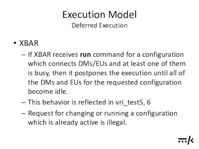
If XBAR receives run command for a configuration
Execution Model
Deferred Execution
XBAR
If XBAR receives run command for a configuration
Execution Model Data Exchange and Data Dependent Execution
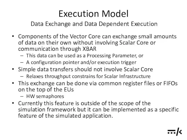
Components of the Vector
Execution Model Data Exchange and Data Dependent Execution
Components of the Vector
Execution Model Data Exchange and Data Dependent Execution
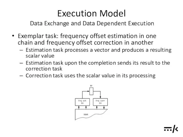
Exemplar task: frequency offset
Execution Model Data Exchange and Data Dependent Execution
Exemplar task: frequency offset
“DESIGN BY SIMULATION” STRATEGY
“DESIGN BY SIMULATION” STRATEGY

HARDWARE CONSIDERATIONS
HARDWARE CONSIDERATIONS
STRUCTURE OF THE SIMULATOR SOFTWARE
STRUCTURE OF THE SIMULATOR SOFTWARE
TESTS AND EXAMPLES
TESTS AND EXAMPLES
vri_test
Verifies system integration and overall functionality
Vector transfers
Block configuration, status and events
vri_test
Verifies system integration and overall functionality
Vector transfers
Block configuration, status and events
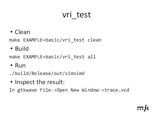
vri_test
Clean
make EXAMPLE=basic/vri_test clean
Build
make EXAMPLE=basic/vri_test all
Run
./build/Release/out/simsimd
Inspect the
vri_test
Clean
make EXAMPLE=basic/vri_test clean
Build
make EXAMPLE=basic/vri_test all
Run
./build/Release/out/simsimd
Inspect the
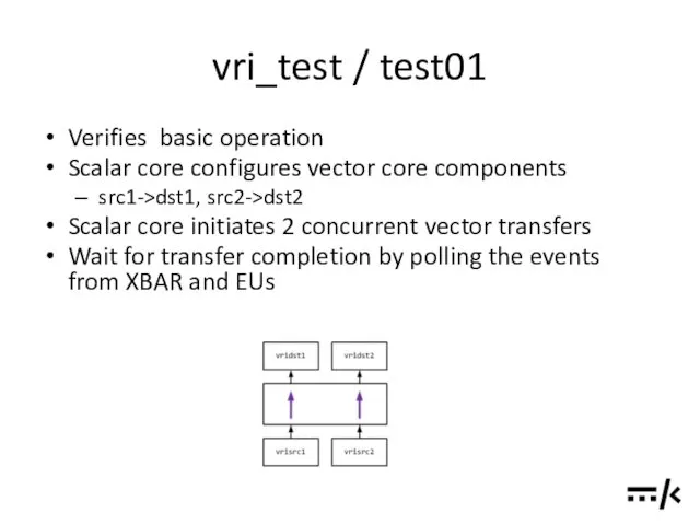
vri_test / test01
Verifies basic operation
Scalar core configures vector core components
src1->dst1, src2->dst2
vri_test / test01
Verifies basic operation
Scalar core configures vector core components
src1->dst1, src2->dst2
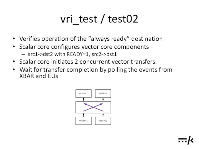
vri_test / test02
Verifies operation of the “always ready” destination
Scalar core configures
vri_test / test02
Verifies operation of the “always ready” destination
Scalar core configures
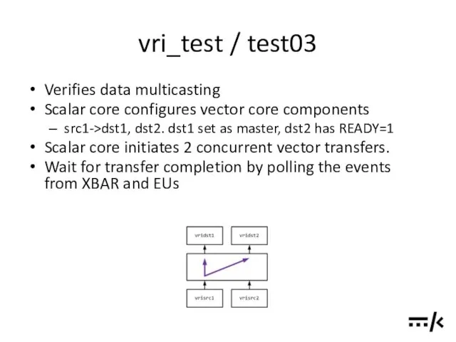
vri_test / test03
Verifies data multicasting
Scalar core configures vector core components
src1->dst1,
vri_test / test03
Verifies data multicasting
Scalar core configures vector core components
src1->dst1,
vri_test / test04
Verifies automatic stepping through the EU and XBAR configuration
vri_test / test04
Verifies automatic stepping through the EU and XBAR configuration
vri_test / test05
Verifies deferred execution in XBAR
Scalar core configures vector core
vri_test / test05
Verifies deferred execution in XBAR
Scalar core configures vector core
vri_test / test06
Verifies deferred execution in XBAR and EUs
Scalar core configures
vri_test / test06
Verifies deferred execution in XBAR and EUs
Scalar core configures
vri_test / test07
Verifies execution priorities
Scalar core configures vector core components to
vri_test / test07
Verifies execution priorities
Scalar core configures vector core components to
dm2dm
Verifies operation of the DM RAM blocks
dm_ram_1rw – Single port RAM
dm2dm
Verifies operation of the DM RAM blocks
dm_ram_1rw – Single port RAM
dm2dm
Clean
make EXAMPLE=basic/dm2dm clean
Build
make EXAMPLE=basic/dm2dm all
Run
./build/Release/out/simsimd
Inspect the
dm2dm
Clean
make EXAMPLE=basic/dm2dm clean
Build
make EXAMPLE=basic/dm2dm all
Run
./build/Release/out/simsimd
Inspect the
dm2dm
Scalar core configures vector core components to execute configuration slots 1..3
dm2dm
Scalar core configures vector core components to execute configuration slots 1..3
dm_init
Verifies initialization of the DM block from .mat file
.mat file is
dm_init
Verifies initialization of the DM block from .mat file
.mat file is
dm_init
Clean
make EXAMPLE=basic/dm_init clean
Build
make EXAMPLE=basic/dm_init all
Generate initialization .mat
dm_init
Clean
make EXAMPLE=basic/dm_init clean
Build
make EXAMPLE=basic/dm_init all
Generate initialization .mat
dm_init
4 regions of dm1 block are initialized from the file at
dm_init
4 regions of dm1 block are initialized from the file at
transp
Verifies operation of the Transparent EU blocks
Synchronous input-to-output transfer: via the
transp
Verifies operation of the Transparent EU blocks
Synchronous input-to-output transfer: via the

transp
Clean
make EXAMPLE=basic/transp clean
Build
make EXAMPLE=basic/transp all
Run
./build/Release/out/simsimd
Inspect the
transp
Clean
make EXAMPLE=basic/transp clean
Build
make EXAMPLE=basic/transp all
Run
./build/Release/out/simsimd
Inspect the
transp
Scalar core configures vector core components to execute single configuration.
src1->transp1->dst1
transp
Scalar core configures vector core components to execute single configuration.
src1->transp1->dst1

TODO’S AND PLANS
TODO’S AND PLANS
Runtime Statistics
For the specific application collect runtime usage data for the
Runtime Statistics
For the specific application collect runtime usage data for the
Runtime Statistics
Logging of the of the XBAR
Switching matrix
For the particular
Runtime Statistics
Logging of the of the XBAR
Switching matrix
For the particular
RTL Code and Testbench Generator
Generate RTL code on the basis of
RTL Code and Testbench Generator
Generate RTL code on the basis of
Common Pool of Address Generators for DMs
Additional cross-bar switch (AG ->
Common Pool of Address Generators for DMs
Additional cross-bar switch (AG ->
Debug Interface for the Vector Core
Debug Interface for the Vector Core
Debug Interface for the Vector Core
Debug Interface for the Vector Core
Data Dump
Data Dump
Data Dump
Data Dump
FXP
FXP
FXP
FXP

REFERENCES
REFERENCES
Source Code and Documentation
https://github.com/timurkelin/simsimd
Source Code and Documentation
https://github.com/timurkelin/simsimd
![Books, Papers and Presentations [1] Bridging dream and reality: Programmable](/_ipx/f_webp&q_80&fit_contain&s_1440x1080/imagesDir/jpg/21006/slide-82.jpg)
Books, Papers and Presentations
[1] Bridging dream and reality: Programmable
baseband processors
Books, Papers and Presentations
[1] Bridging dream and reality: Programmable
baseband processors
![Standards and Datasheets [3] AMBA 4 AXI4-Stream Protocol Specification, Version:](/_ipx/f_webp&q_80&fit_contain&s_1440x1080/imagesDir/jpg/21006/slide-83.jpg)
Standards and Datasheets
[3] AMBA 4 AXI4-Stream Protocol Specification,
Version: 1.0, (c)
Standards and Datasheets
[3] AMBA 4 AXI4-Stream Protocol Specification,
Version: 1.0, (c)
 Позиционные системы счисления
 Локальные сети. Параметры сетей и их стандарты
 Сбор и подготовка данных
 Современные накопители информации, используемые в вычислительной технике
 Использование технологии веб-квест как средство развития познавательных и творческих способностей учащихся
 Блочные алгоритмы. Блочное шифрование. Сравнение блочных и поточных шифров. Предпосылки создания шифра Фейстеля
 Параллельное программирование. С++. Thread Support Library. Atomic Operations Library
 Функции в Excel
 Организация и средства информационных технологий обеспечения управленческой деятельности
 Поиск публикаций и показатели деятельности ученого в Web of Science
 Бездротові мережі
 Занятие 1. Знакомство с программой Adobe Photoshop
 Microsoft Visual Studio — линейка продуктов компании Microsoft
 Операторы цикла
 Понятие об информации. Представление информации. Информационная деятельность человека.
 Автоматизоване створення запитів у базі даних
 Архітектура операційних систем
 Windows System Programming
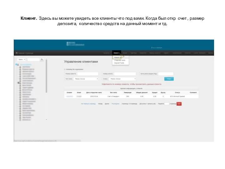 Личный кабинет
 Мир станочника. Аддитивные технологии и 3D-сканирование
 Методы и средства защиты программ от компьютерных вирусов
 46_Yaroslavskaya_Sasha
 Локальные и глобальные сети ЭВМ. Защита информации в сетях. (Тема 6)
 Godseeker. Игра
 Рабочий стол. Управление компьютером с помощью мыши
 Проектирование изделий из листового металла в NX
 Эти люди изменили мир
 Электронные ресурсы для детей и юношества в общедоступных библиотеках: создание и использование