- E -doctor user’s manual

Содержание
- 2. e-Doctor is to - Show engine failure Current status and history. - View each engine components
- 3. e-Doctor Kit Components (P/N : K9001683) Program Installation CD Gate way (Module) Main Harness (Module /
- 4. Wiring e-Doctor with machine and laptop 4 ← Lap top (USB or Serial Port) Machine →
- 5. Install program Insert program install CD in your lap top computer - Copy and save “USB
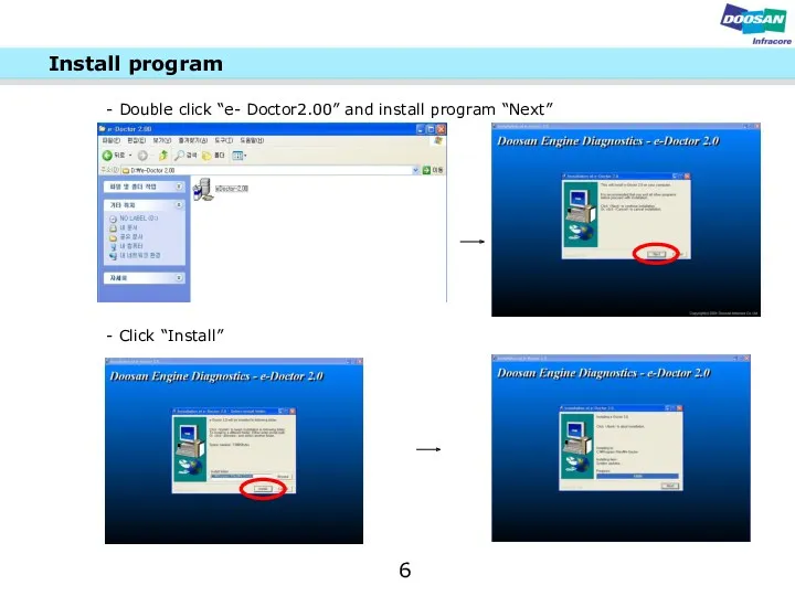
- 6. Install program - Double click “e- Doctor2.00” and install program “Next” - Click “Install” 6
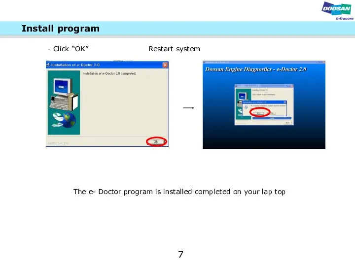
- 7. Install program - Click “OK” Restart system The e- Doctor program is installed completed on your
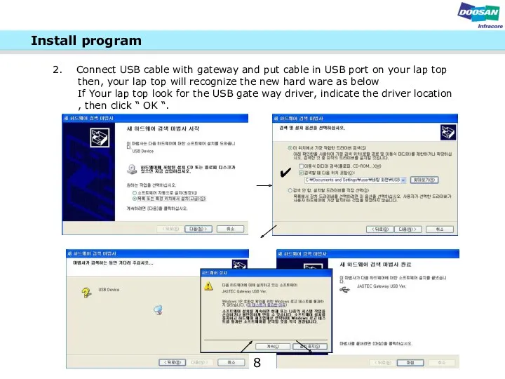
- 8. Install program Connect USB cable with gateway and put cable in USB port on your lap
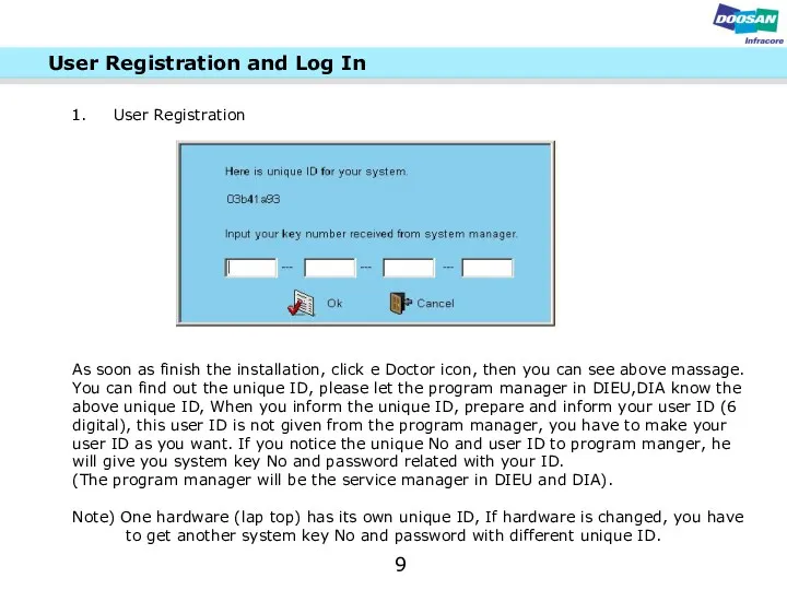
- 9. User Registration and Log In User Registration As soon as finish the installation, click e Doctor
- 10. If you fill the system key No which is acquired from the program manager, you can
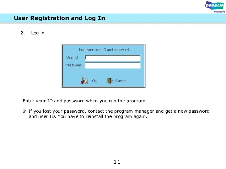
- 11. Log in Enter your ID and password when you run the program. ※ If you lost
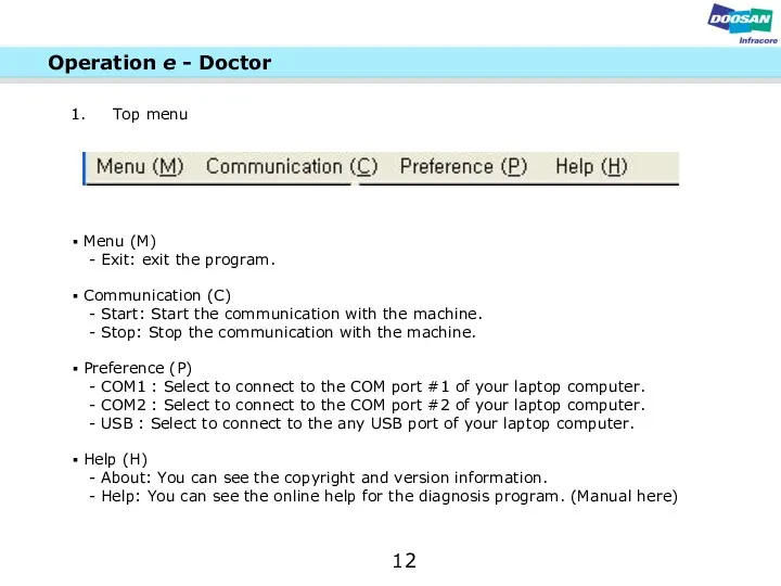
- 12. Operation e - Doctor Top menu Menu (M) - Exit: exit the program. Communication (C) -
- 13. Start communication icon - Make the e Doctor and engine ECU communicate. - Let you know
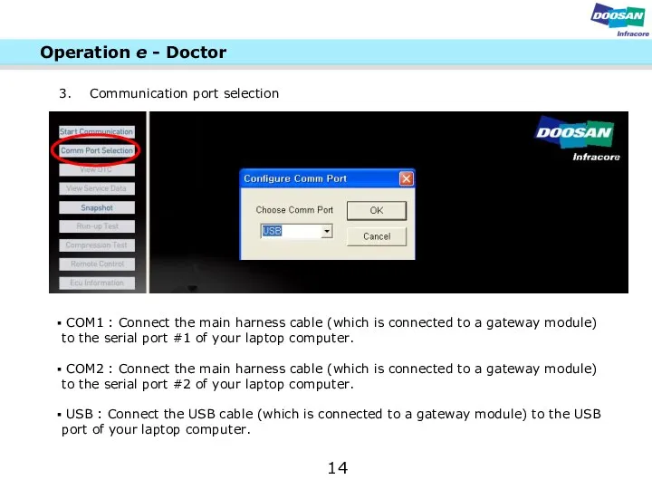
- 14. Communication port selection COM1 : Connect the main harness cable (which is connected to a gateway
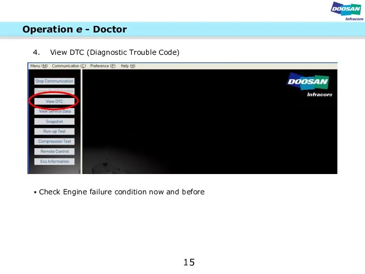
- 15. View DTC (Diagnostic Trouble Code) Check Engine failure condition now and before 15 Operation e -
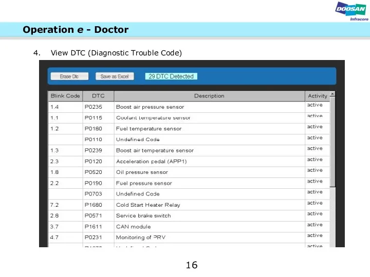
- 16. View DTC (Diagnostic Trouble Code) 16 Operation e - Doctor
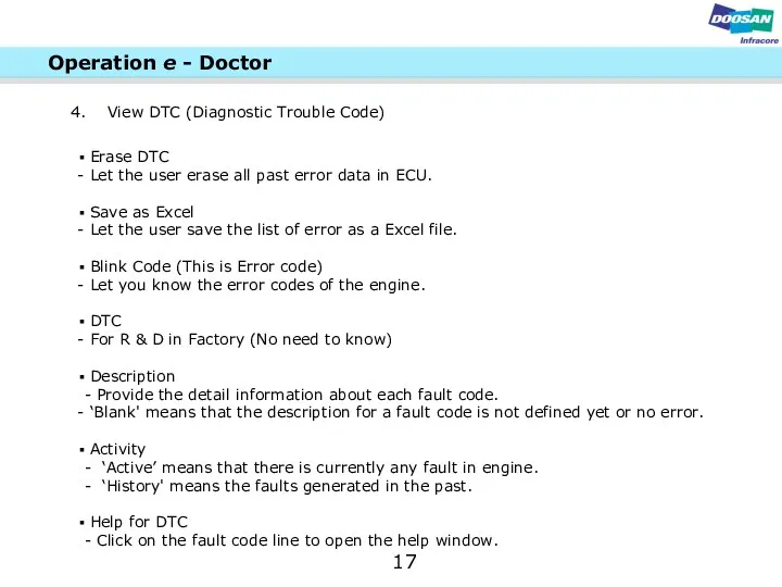
- 17. Erase DTC Let the user erase all past error data in ECU. Save as Excel Let
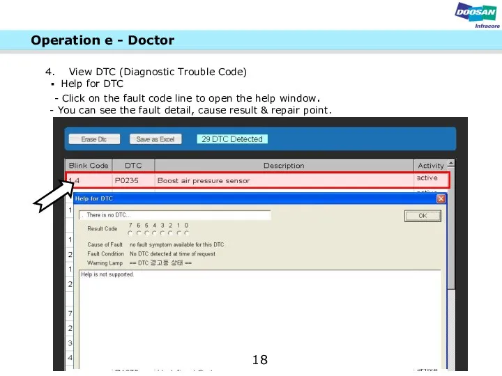
- 18. View DTC (Diagnostic Trouble Code) Help for DTC - Click on the fault code line to
- 19. Result Code (Fault Status) - 0 Bit – Higher output voltage than the max(4850mV) limit -
- 20. View Service Data View service data enables you to check the sensors and service data values
- 21. View Service Data 21 Operation e - Doctor
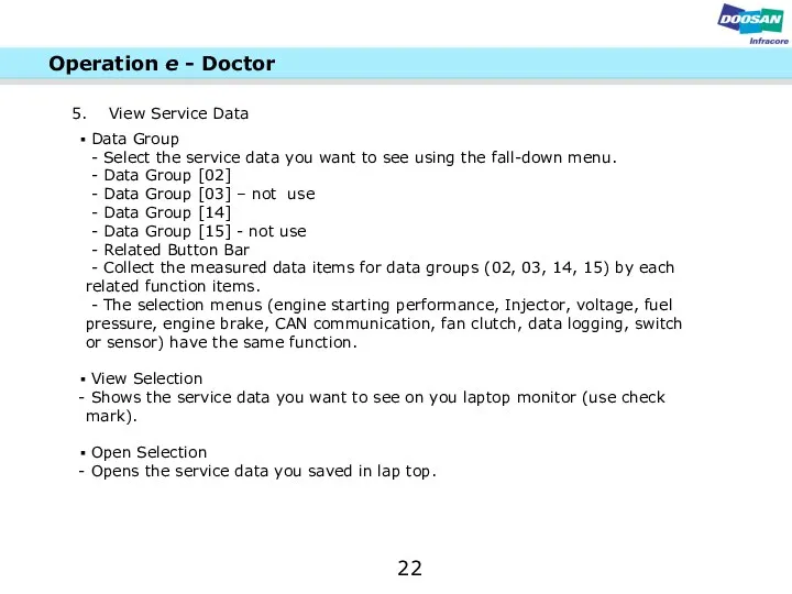
- 22. View Service Data Data Group - Select the service data you want to see using the
- 23. View Service Data Save Selection - You can save the specified service data which you selected
- 24. View Service Data 24 Operation e - Doctor
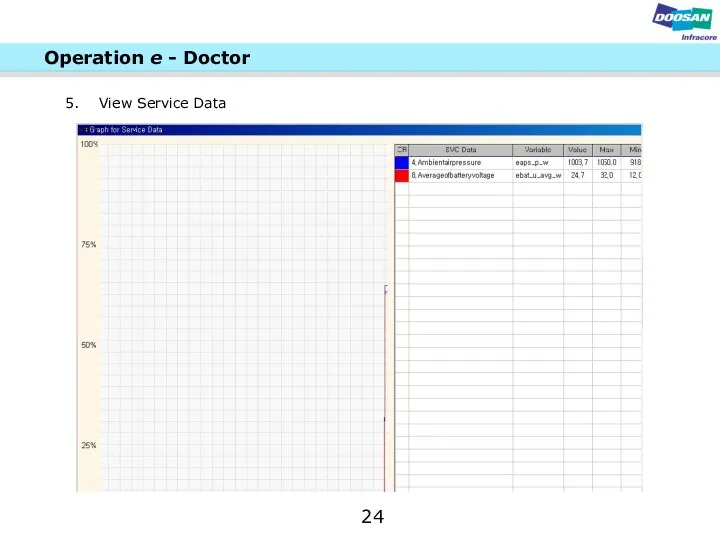
- 25. View Service Data Graph - Color: Indicates the line color on the graph. - Service Data
- 26. View Service Data Sensor condition - If click any column of current value line, you can
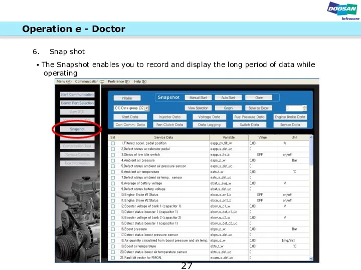
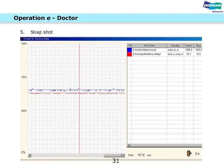
- 27. Snap shot The Snapshot enables you to record and display the long period of data while
- 28. Snap shot Initialize - The Initialize icon has the same function as the service data check.
- 29. Snap shot Manual Start - Data can be saved up to 200 seconds (100 seconds before
- 30. Graph - It will be activated when selecting to save the snapshot manually or automatically. -
- 31. Snap shot 31 Operation e - Doctor
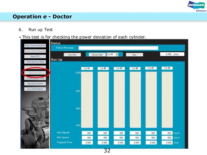
- 32. Run up Test This test is for checking the power deviation of each cylinder. 32 Operation
- 33. Auto Start icon - Start and idle the engine before clicking the Auto Start icon. -
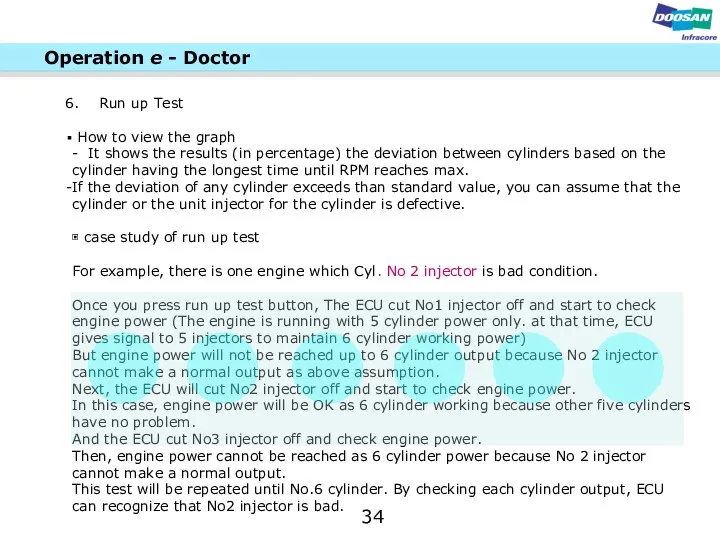
- 34. How to view the graph - It shows the results (in percentage) the deviation between cylinders
- 35. This is to check the deviation of the compression function of each cylinders. Compression Test 35
- 36. Start icon - Be sure compression test must be conducted on “ Key On “position after
- 37. Remote control This is to test ECU when the user provided abnormal signal. You can check
- 38. Remote control View current value - Show current working value Start remote control - Start remote
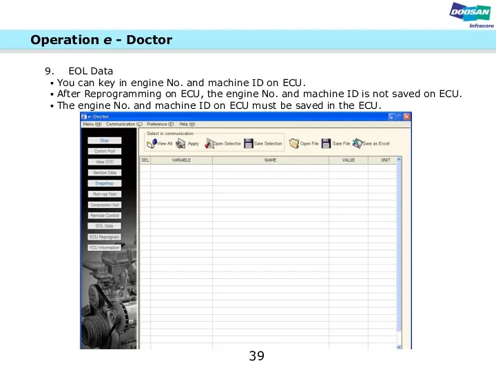
- 39. EOL Data 39 You can key in engine No. and machine ID on ECU. After Reprogramming
- 40. 40 Select in communication - View all : Click view all icon, you can see the
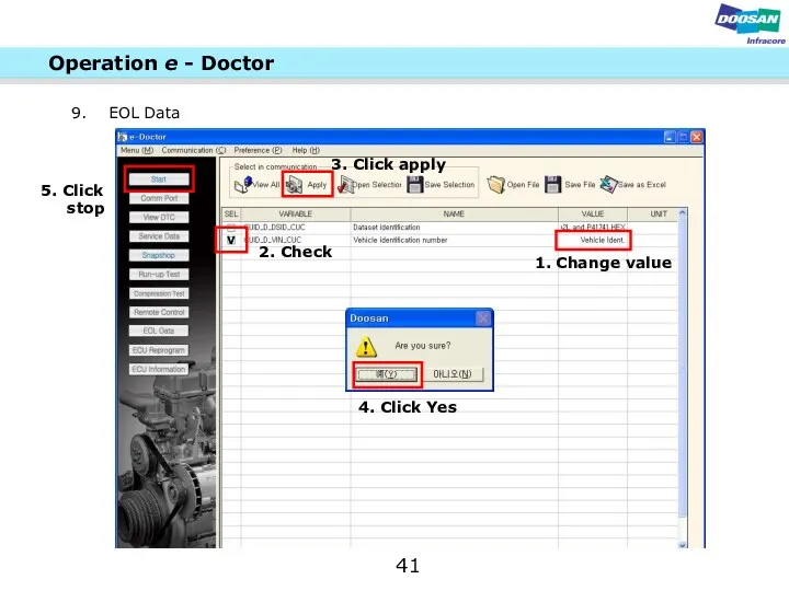
- 41. 41 Operation e - Doctor V 1. Change value 2. Check 3. Click apply 4. Click
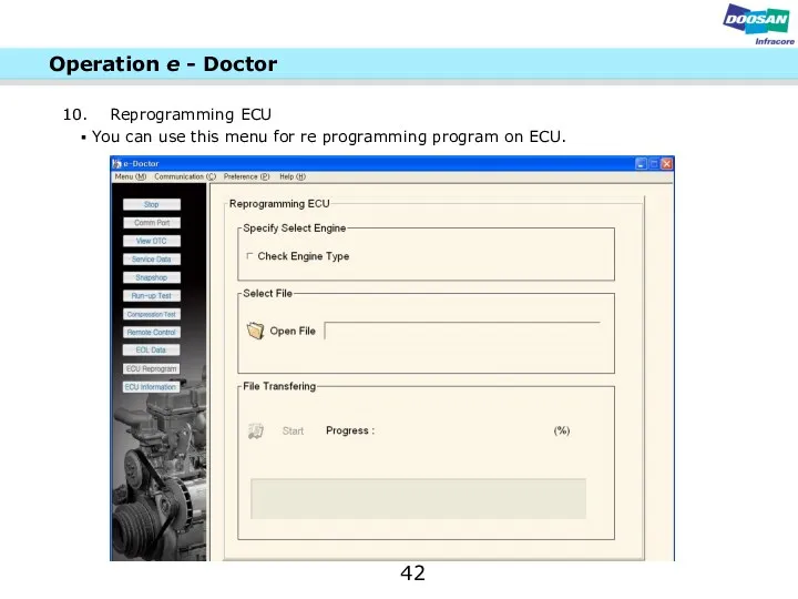
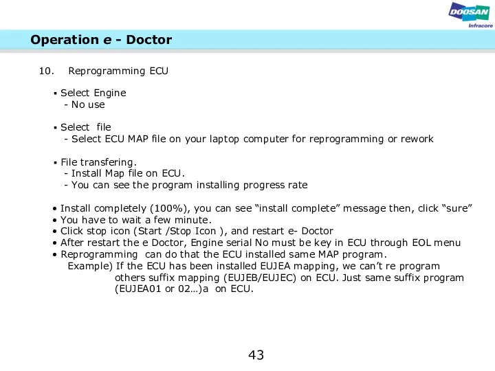
- 42. Reprogramming ECU 42 You can use this menu for re programming program on ECU. Operation e
- 43. 43 Select Engine - No use Select file - Select ECU MAP file on your laptop
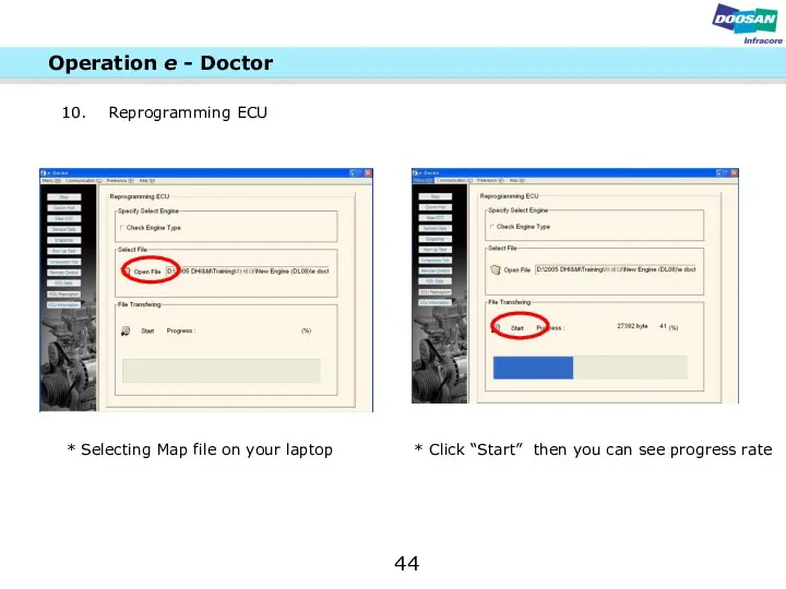
- 44. 44 Operation e - Doctor * Selecting Map file on your laptop * Click “Start” then
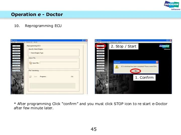
- 45. 45 Operation e - Doctor Reprogramming ECU * After programming Click “confirm” and you must click
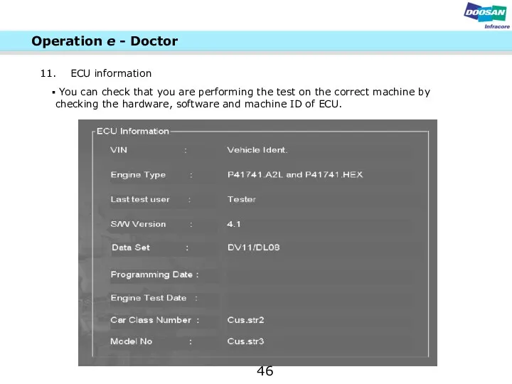
- 46. You can check that you are performing the test on the correct machine by checking the
- 47. VIN - Machine Identification number Engine Type - Suffix / Engine Number Last test user -
- 49. Скачать презентацию
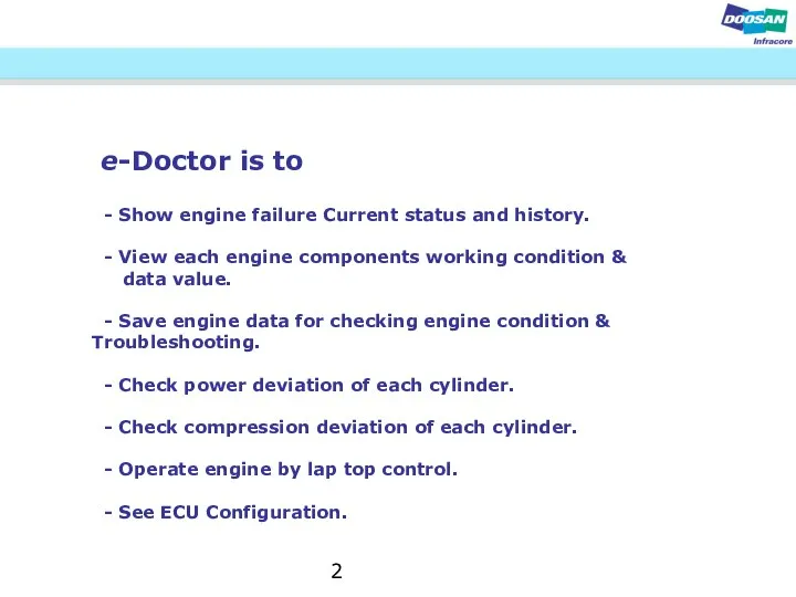
e-Doctor is to
- Show engine failure Current status
e-Doctor is to
- Show engine failure Current status
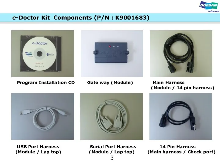
e-Doctor Kit Components (P/N : K9001683)
Program Installation CD Gate way
e-Doctor Kit Components (P/N : K9001683)
Program Installation CD Gate way
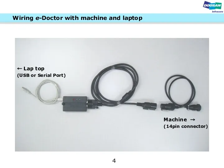
Wiring e-Doctor with machine and laptop
4
← Lap top
(USB or
Wiring e-Doctor with machine and laptop
4
← Lap top
(USB or
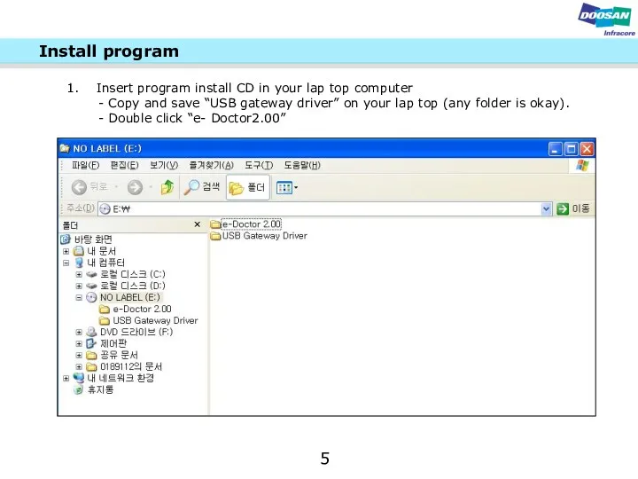
Install program
Insert program install CD in your lap top computer
Install program
Insert program install CD in your lap top computer
Install program
- Double click “e- Doctor2.00” and install program
Install program
- Double click “e- Doctor2.00” and install program
Install program
- Click “OK” Restart system
The e- Doctor
Install program
- Click “OK” Restart system
The e- Doctor
Install program
Connect USB cable with gateway and put cable in
Install program
Connect USB cable with gateway and put cable in
User Registration and Log In
User Registration
As soon as
User Registration and Log In
User Registration
As soon as
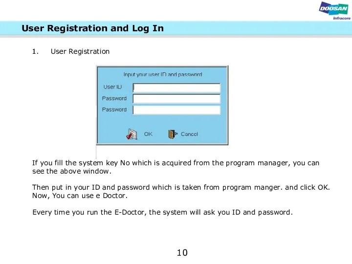
If you fill the system key No which is acquired from
If you fill the system key No which is acquired from
Log in
Enter your ID and password when you run the
Log in
Enter your ID and password when you run the
Operation e - Doctor
Top menu
Menu (M)
- Exit:
Operation e - Doctor
Top menu
Menu (M)
- Exit:
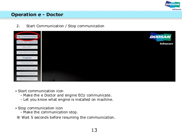
Start communication icon
- Make the e Doctor and
Start communication icon
- Make the e Doctor and
Communication port selection
COM1 : Connect the main harness cable (which
Communication port selection
COM1 : Connect the main harness cable (which
View DTC (Diagnostic Trouble Code)
Check Engine failure condition now
View DTC (Diagnostic Trouble Code)
Check Engine failure condition now
View DTC (Diagnostic Trouble Code)
16
Operation e - Doctor
View DTC (Diagnostic Trouble Code)
16
Operation e - Doctor
Erase DTC
Let the user erase all past error data
Erase DTC
Let the user erase all past error data
View DTC (Diagnostic Trouble Code)
Help for DTC
- Click
View DTC (Diagnostic Trouble Code)
Help for DTC
- Click
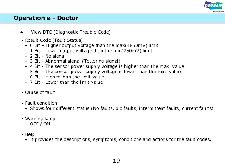
Result Code (Fault Status)
- 0 Bit – Higher output voltage
Result Code (Fault Status)
- 0 Bit – Higher output voltage
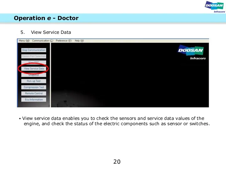
View Service Data
View service data enables you to check
View Service Data
View service data enables you to check
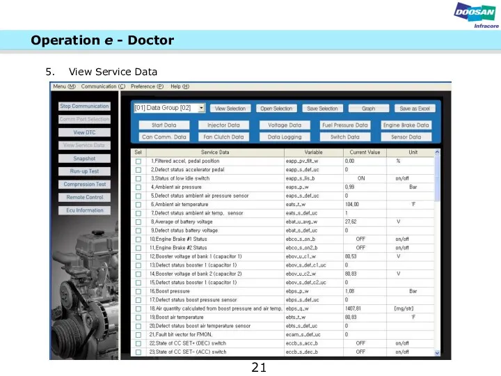
View Service Data
21
Operation e - Doctor
View Service Data
21
Operation e - Doctor
View Service Data
Data Group
- Select the service
View Service Data
Data Group
- Select the service
View Service Data
Save Selection
- You can save
View Service Data
Save Selection
- You can save
View Service Data
24
Operation e - Doctor
View Service Data
24
Operation e - Doctor
View Service Data
Graph
- Color: Indicates the line
View Service Data
Graph
- Color: Indicates the line

View Service Data
Sensor condition
- If click any column
View Service Data
Sensor condition
- If click any column
Snap shot
The Snapshot enables you to record and display
Snap shot
The Snapshot enables you to record and display
Snap shot
Initialize
- The Initialize icon has the same function
Snap shot
Initialize
- The Initialize icon has the same function
Snap shot
Manual Start
- Data can be saved up
Snap shot
Manual Start
- Data can be saved up
Graph
- It will be activated when selecting to
Graph
- It will be activated when selecting to
Snap shot
31
Operation e - Doctor
Snap shot
31
Operation e - Doctor
Run up Test
This test is for checking the power
Run up Test
This test is for checking the power
Auto Start icon
- Start and idle the engine
Auto Start icon
- Start and idle the engine
How to view the graph
- It shows the results
How to view the graph
- It shows the results
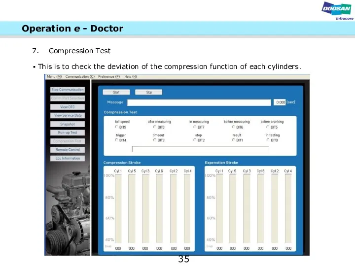
This is to check the deviation of the compression function
This is to check the deviation of the compression function
Start icon
- Be sure compression test must be
Start icon
- Be sure compression test must be
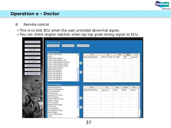
Remote control
This is to test ECU when the user
Remote control
This is to test ECU when the user
Remote control
View current value
- Show current working
Remote control
View current value
- Show current working
EOL Data
39
You can key in engine No. and machine ID
EOL Data
39
You can key in engine No. and machine ID
40
Select in communication
- View all : Click view all
40
Select in communication
- View all : Click view all
41
Operation e - Doctor
V
1. Change value
2. Check
3. Click apply
4. Click
41
Operation e - Doctor
V
1. Change value
2. Check
3. Click apply
4. Click
Reprogramming ECU
42
You can use this menu for re programming program
Reprogramming ECU
42
You can use this menu for re programming program
43
Select Engine
- No use
Select file
-
43
Select Engine
- No use
Select file
-
44
Operation e - Doctor
* Selecting Map file on your laptop *
44
Operation e - Doctor
* Selecting Map file on your laptop *
45
Operation e - Doctor
Reprogramming ECU
* After programming Click “confirm” and you
45
Operation e - Doctor
Reprogramming ECU
* After programming Click “confirm” and you
You can check that you are performing the test on
You can check that you are performing the test on
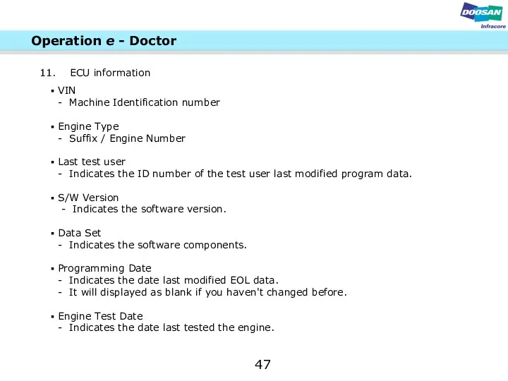
VIN
- Machine Identification number
Engine Type
- Suffix
VIN
- Machine Identification number
Engine Type
- Suffix
 Презентация к уроку Циклы на паскале
 Данные. Виды и типы данных
 Понятие мультимедиа
 Презентация к занятию по внеурочной деятельности: Возникновение мультипликации
 Библиографическое описание для составления списка литературы
 Фреймворки. Популярные фреймворки для веб-разработки
 Перечень опасных событий. Модели угроз нарушителя и модель защиты от компьютерных атак. (Лекция 3)
 Лекция 3. Виды компьютерной графики
 Тестирование ПО. Виды тестирования. Лекция 4
 Операции, линейный алгоритм. (Семинар 1-3)
 Программное обеспечение
 Внедрение Битрикс24 в сфере услуг
 Информация в живой и неживой природе
 Дискретные и непрерывные модели
 Компьютер и его части. 2 класс
 Основы программирования на языке Паскаль
 А что такое ОС?
 Основы программирования на языке высокого уровня. Модуль 1
 Переход от REST API к GraphQL на примере реальных проектов
 Урок по теме Действия с фрагментом рисунка в графическом редакторе Paint
 Доменная система имён. Протоколы передачи данных
 Курсоры. Типы курсоров в Т-SQL
 Информационная культура
 Развитие автомобильных телеканалов в 2019 г
 Язык программирования Python
 Курсовий проект. Побудова графіку функції за наданим користувачем рядком, що містить припустимий опис функції
 Технологии аналитики и визуализации больших данных (лекция № 7)
 Социальные сети: почему люди предпочитают живому общению виртуальное?