- Flight controls

Содержание
- 2. We will begin this module by explaining the basic concept of the “Fly By Wire“ system.
- 3. This has the advantage of saving weight on the aircraft, However, there are, even greater advantages
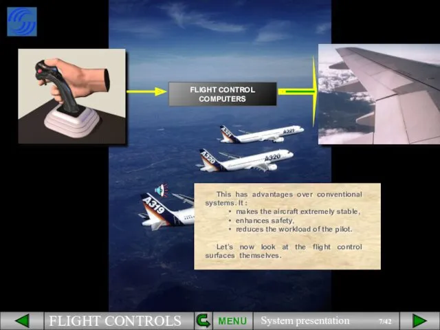
- 6. The electrical signals created by sidestick movement travel through flight control computers before being passed to
- 7. MENU This has advantages over conventional systems. It : makes the aircraft extremely stable, enhances safety,
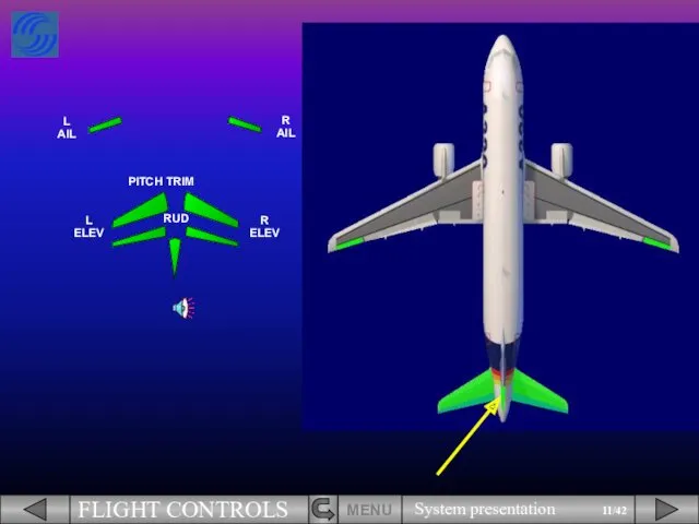
- 10. PITCH TRIM
- 11. PITCH TRIM RUD
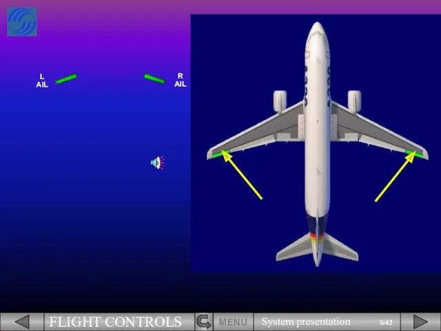
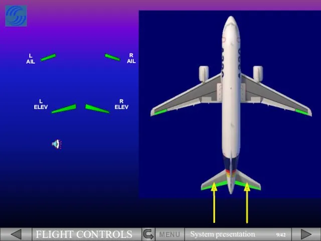
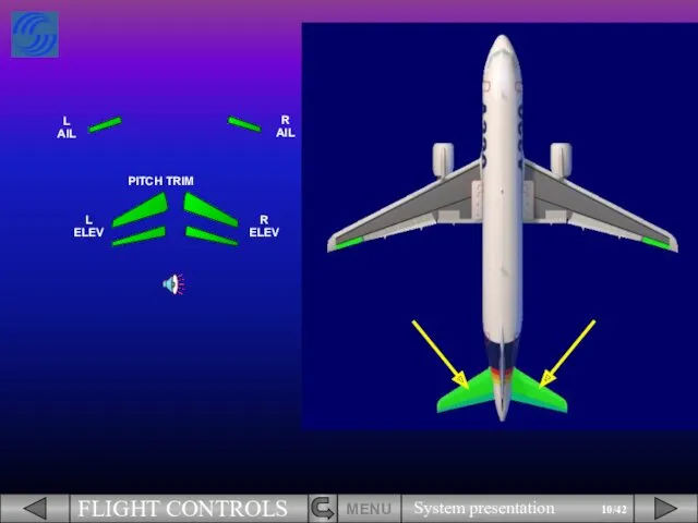
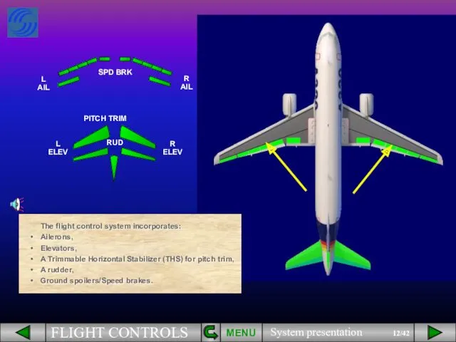
- 12. PITCH TRIM A rudder, RUD The flight control system incorporates: Ailerons, A Trimmable Horizontal Stabilizer (THS)
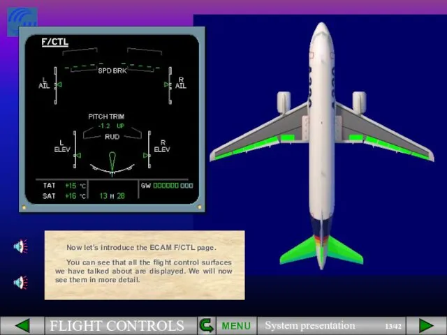
- 13. PITCH TRIM RUD Now let’s introduce the ECAM F/CTL page. You can see that all the
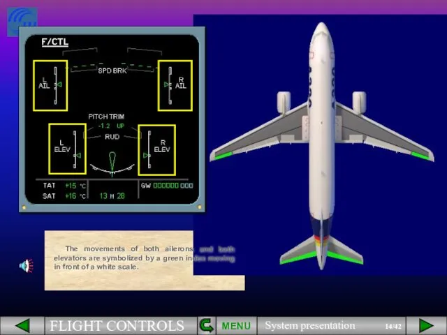
- 14. The movements of both ailerons and both elevators are symbolized by a green index moving in
- 15. The green rudder symbol is used as an index to display the movements of the rudder
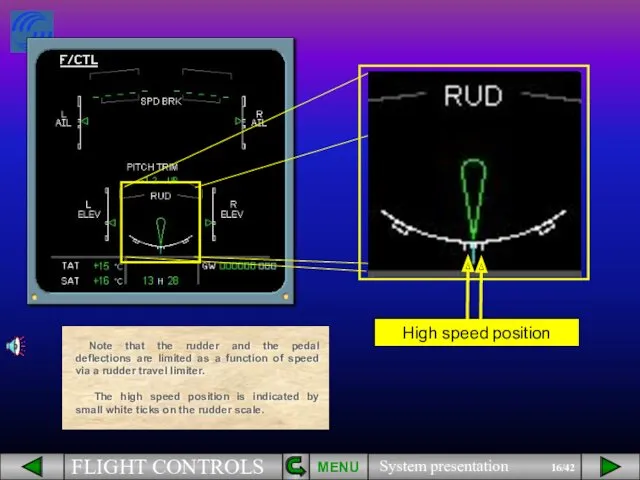
- 16. MENU High speed position Note that the rudder and the pedal deflections are limited as a
- 17. The PITCH TRIM position is indicated by THS deflection in degrees up or down. Let’s continue
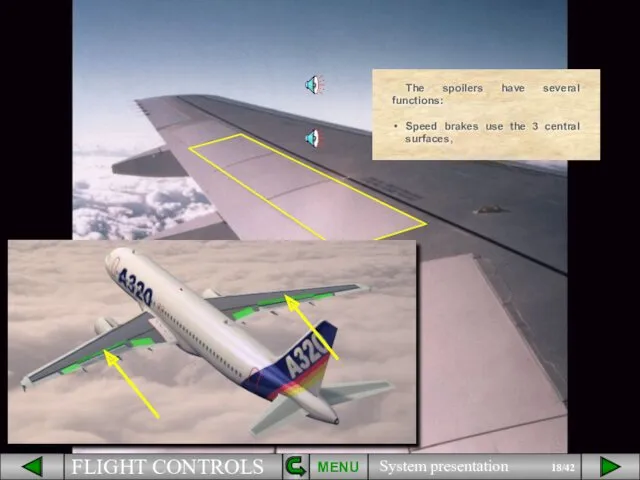
- 18. MENU The spoilers have several functions: Speed brakes use the 3 central surfaces,
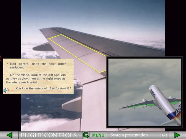
- 19. MENU Roll control uses the four outer surfaces, On the video, look at the left spoilers
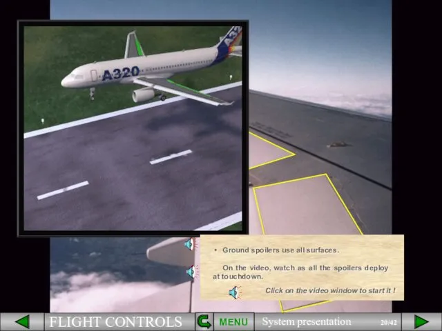
- 20. MENU Ground spoilers use all surfaces. On the video, watch as all the spoilers deploy at
- 21. On the ECAM F/CTL page, the spoiler extended position is indicated by small arrows. This is
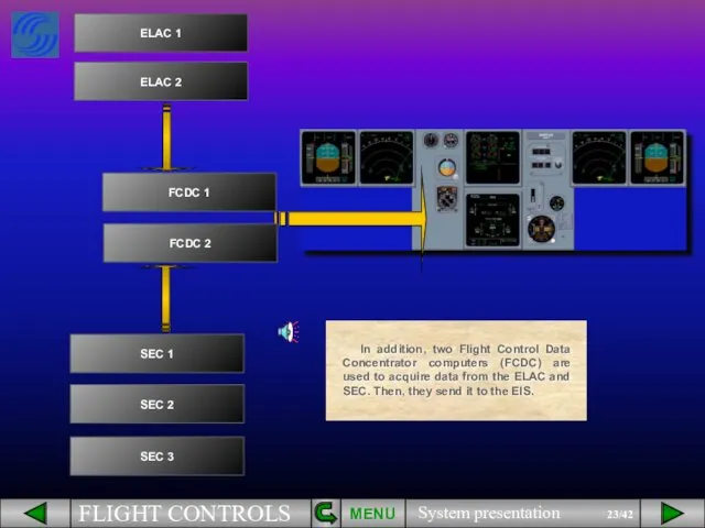
- 22. Two ELevator and Aileron Computers (ELAC), Three Spoiler and Elevator Computers (SEC), Two Flight Augmentation Computers
- 23. In addition, two Flight Control Data Concentrator computers (FCDC) are used to acquire data from the
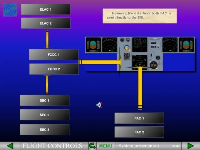
- 24. However, the data from both FAC is sent directly to the EIS. MENU
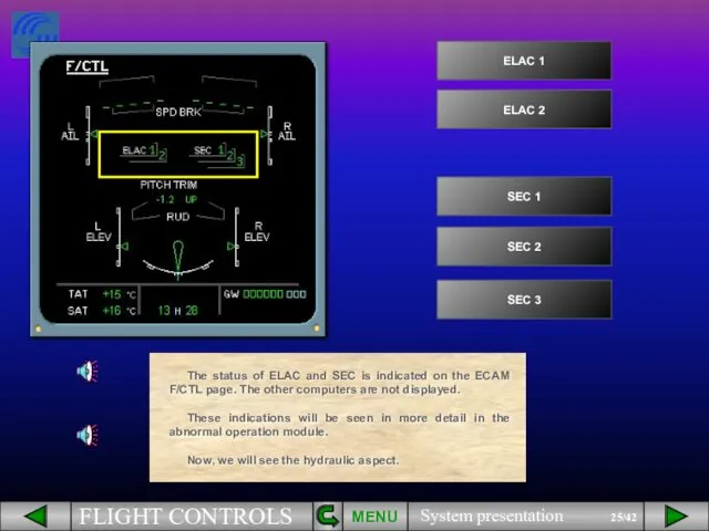
- 25. The status of ELAC and SEC is indicated on the ECAM F/CTL page. The other computers
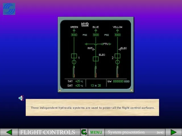
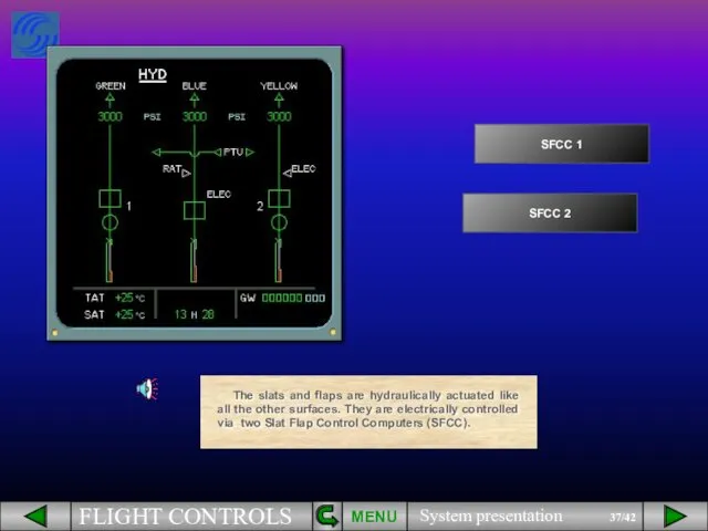
- 26. Three independent hydraulic systems are used to power all the flight control surfaces. MENU
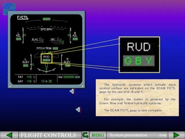
- 27. MENU The hydraulic systems which actuate each control surface are indicated on the ECAM F/CTL page
- 28. Pilots control pitch and roll through two side sticks. MENU
- 29. There are associated side stick priority lights. Side sticks and priority lights will be explained in
- 30. Pitch trim wheels are located on the center pedestal. MENU
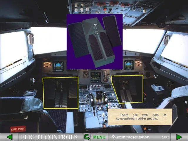
- 31. MENU There are two sets of conventional rudder pedals.
- 32. A RUD TRIM panel is located on the pedestal. MENU
- 33. A speed brake lever is located on the left side of the pedestal. MENU
- 34. In addition, there are two panels, located on the overhead panel to control the flight control
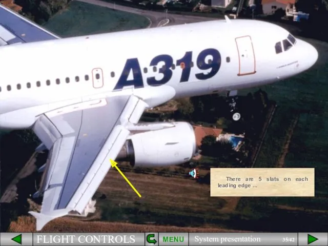
- 35. There are 5 slats on each leading edge ... MENU
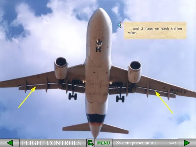
- 36. and 2 flaps on each trailing edge. MENU
- 37. The slats and flaps are hydraulically actuated like all the other surfaces. They are electrically controlled
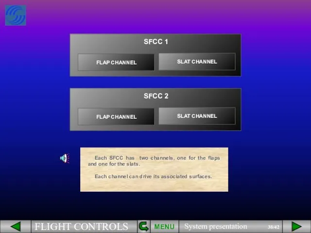
- 38. Each SFCC has two channels, one for the flaps and one for the slats. Each channel
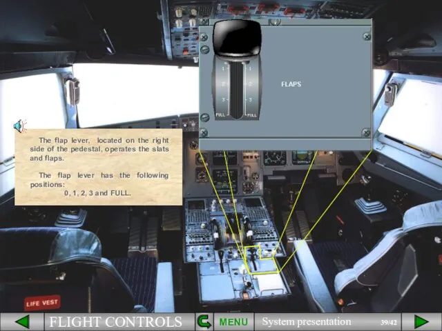
- 39. The flap lever, located on the right side of the pedestal, operates the slats and flaps.
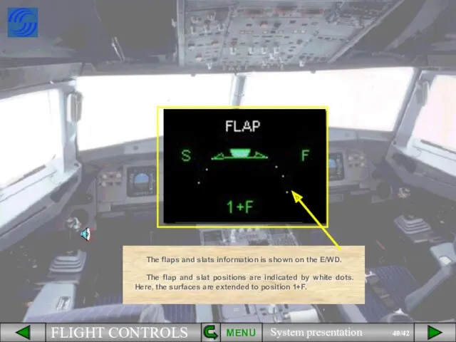
- 40. The flaps and slats information is shown on the E/WD. The flap and slat positions are
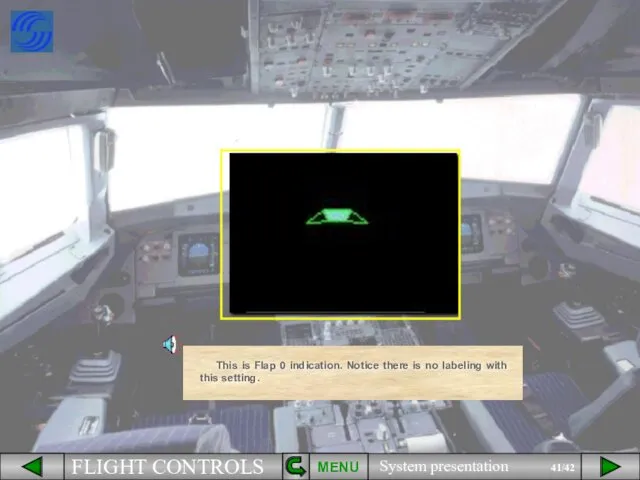
- 41. This is Flap 0 indication. Notice there is no labeling with this setting. MENU
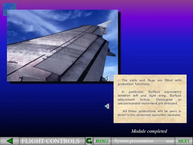
- 42. The slats and flaps are fitted with protection functions. In particular, Surface asymmetry between left and
- 44. Скачать презентацию
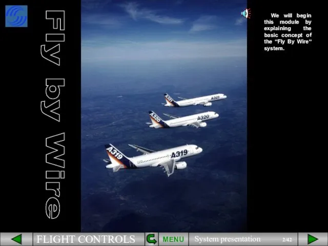
We will begin this module by explaining the basic concept of
We will begin this module by explaining the basic concept of
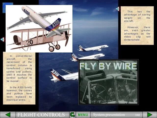
This has the advantage of saving weight on the aircraft,
However, there
This has the advantage of saving weight on the aircraft,
However, there

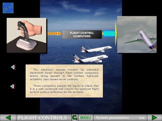
The electrical signals created by sidestick movement travel through flight control
The electrical signals created by sidestick movement travel through flight control
MENU
This has advantages over conventional systems. It :
makes the aircraft extremely
MENU
This has advantages over conventional systems. It :
makes the aircraft extremely
PITCH TRIM
PITCH TRIM
PITCH TRIM
RUD
PITCH TRIM
RUD
PITCH TRIM
A rudder,
RUD
The flight control system incorporates:
Ailerons,
A Trimmable Horizontal Stabilizer (THS)
PITCH TRIM
A rudder,
RUD
The flight control system incorporates:
Ailerons,
A Trimmable Horizontal Stabilizer (THS)
PITCH TRIM
RUD
Now let’s introduce the ECAM F/CTL page.
You can see that
PITCH TRIM
RUD
Now let’s introduce the ECAM F/CTL page.
You can see that
The movements of both ailerons and both elevators are symbolized by
The movements of both ailerons and both elevators are symbolized by
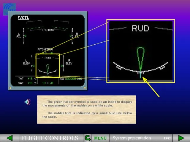
The green rudder symbol is used as an index to display
The green rudder symbol is used as an index to display
MENU
High speed position
Note that the rudder and the pedal deflections are
MENU
High speed position
Note that the rudder and the pedal deflections are
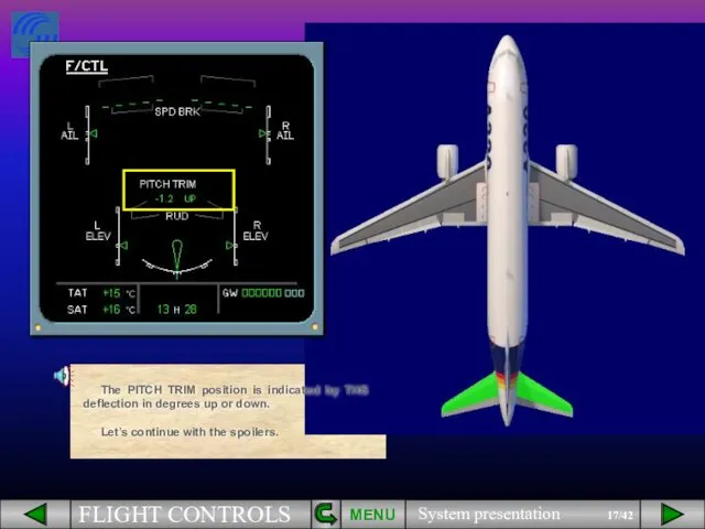
The PITCH TRIM position is indicated by THS deflection in degrees
The PITCH TRIM position is indicated by THS deflection in degrees
MENU
The spoilers have several functions:
Speed brakes use the 3 central surfaces,
MENU
The spoilers have several functions:
Speed brakes use the 3 central surfaces,
MENU
Roll control uses the four outer surfaces,
On the video, look at
MENU
Roll control uses the four outer surfaces,
On the video, look at
MENU
Ground spoilers use all surfaces.
On the video, watch as all the
MENU
Ground spoilers use all surfaces.
On the video, watch as all the
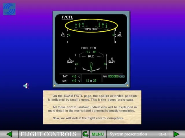
On the ECAM F/CTL page, the spoiler extended position is indicated
On the ECAM F/CTL page, the spoiler extended position is indicated
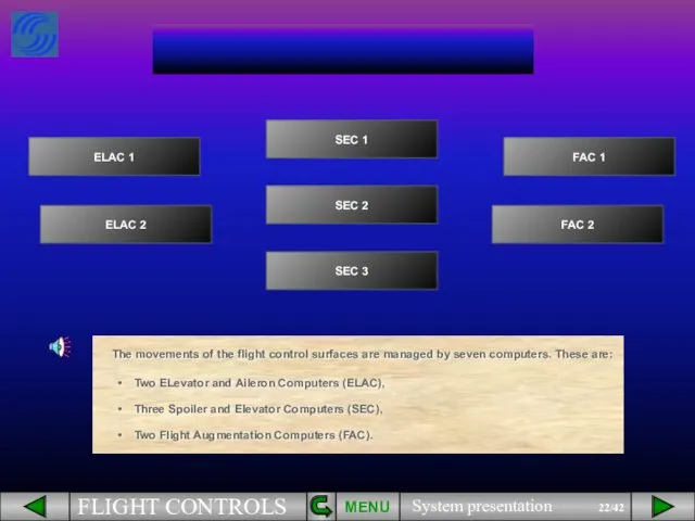
Two ELevator and Aileron Computers (ELAC),
Three Spoiler and Elevator Computers (SEC),
Two
Two ELevator and Aileron Computers (ELAC),
Three Spoiler and Elevator Computers (SEC),
Two
In addition, two Flight Control Data Concentrator computers (FCDC) are used
In addition, two Flight Control Data Concentrator computers (FCDC) are used
However, the data from both FAC is sent directly to the
However, the data from both FAC is sent directly to the
The status of ELAC and SEC is indicated on the ECAM
The status of ELAC and SEC is indicated on the ECAM
Three independent hydraulic systems are used to power all the flight
Three independent hydraulic systems are used to power all the flight
MENU
The hydraulic systems which actuate each control surface are indicated on
MENU
The hydraulic systems which actuate each control surface are indicated on
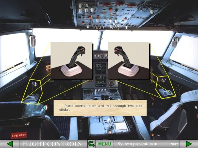
Pilots control pitch and roll through two side sticks.
MENU
Pilots control pitch and roll through two side sticks.
MENU
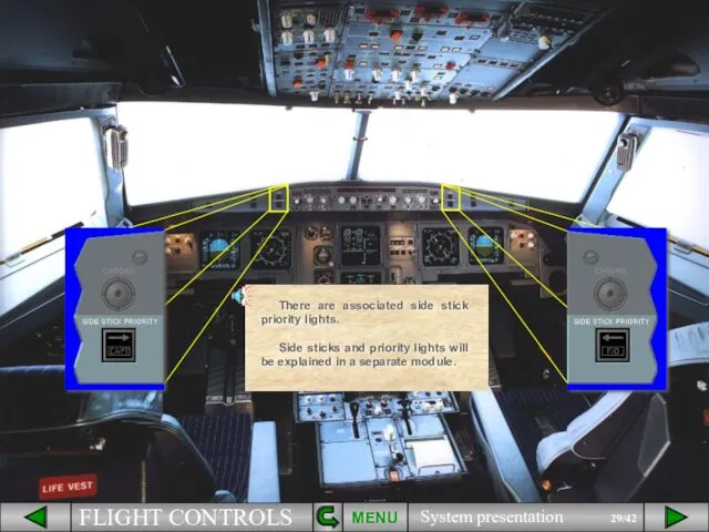
There are associated side stick priority lights.
Side sticks and priority lights
There are associated side stick priority lights.
Side sticks and priority lights
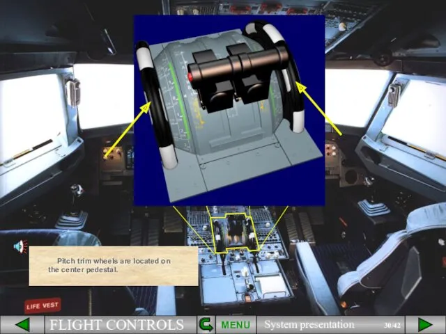
Pitch trim wheels are located on the center pedestal.
MENU
Pitch trim wheels are located on the center pedestal.
MENU
MENU
There are two sets of conventional rudder pedals.
MENU
There are two sets of conventional rudder pedals.
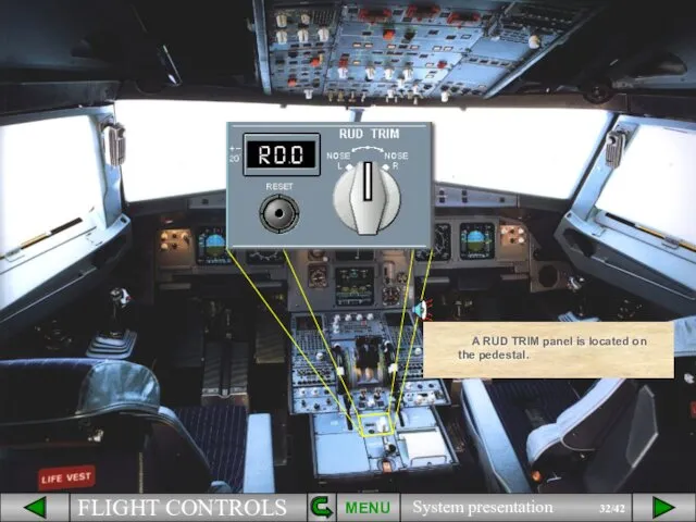
A RUD TRIM panel is located on the pedestal.
MENU
A RUD TRIM panel is located on the pedestal.
MENU
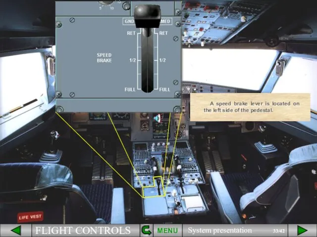
A speed brake lever is located on the left side of
A speed brake lever is located on the left side of
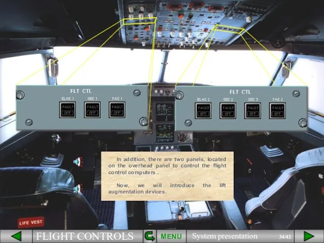
In addition, there are two panels, located on the overhead panel
In addition, there are two panels, located on the overhead panel
There are 5 slats on each leading edge ...
MENU
There are 5 slats on each leading edge ...
MENU
and 2 flaps on each trailing edge.
MENU
and 2 flaps on each trailing edge.
MENU
The slats and flaps are hydraulically actuated like all the other
The slats and flaps are hydraulically actuated like all the other
Each SFCC has two channels, one for the flaps and one
Each SFCC has two channels, one for the flaps and one
The flap lever, located on the right side of the pedestal,
The flap lever, located on the right side of the pedestal,
The flaps and slats information is shown on the E/WD.
The flap
The flaps and slats information is shown on the E/WD.
The flap
This is Flap 0 indication. Notice there is no labeling with
This is Flap 0 indication. Notice there is no labeling with
The slats and flaps are fitted with protection functions.
In particular, Surface
The slats and flaps are fitted with protection functions.
In particular, Surface
 Алгоритмы
 Компьютерная графика (Autodesk 3ds max). Лекция 8. Текстурные карты
 Урок по информатике для 10 класса по теме Что такое система? Информационные процессы.
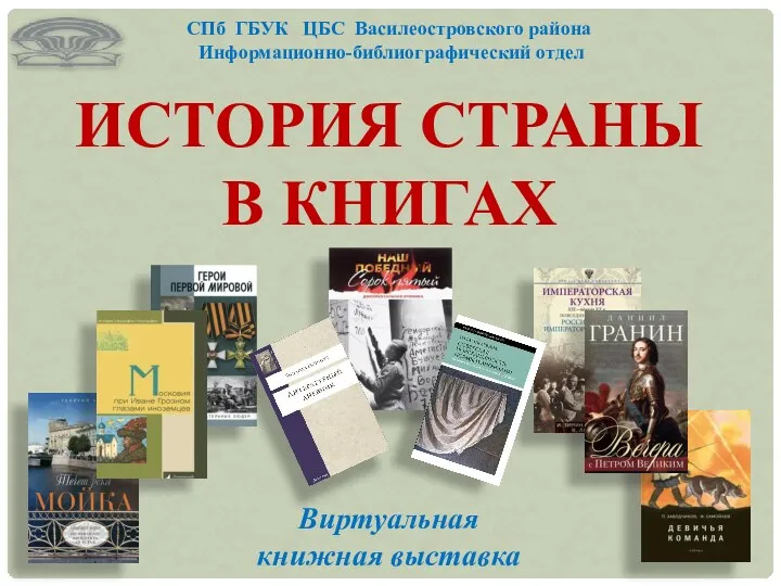 СПб ГБУК ЦБС Василеостровского района. Информационно-библиографический отдел. История страны в книгах
 Разработка алгоритма по сказке Репка
 Презентации
 Зимняя школа журналистики. Программа
 Списки. Элемент списка. (Лекция 2)
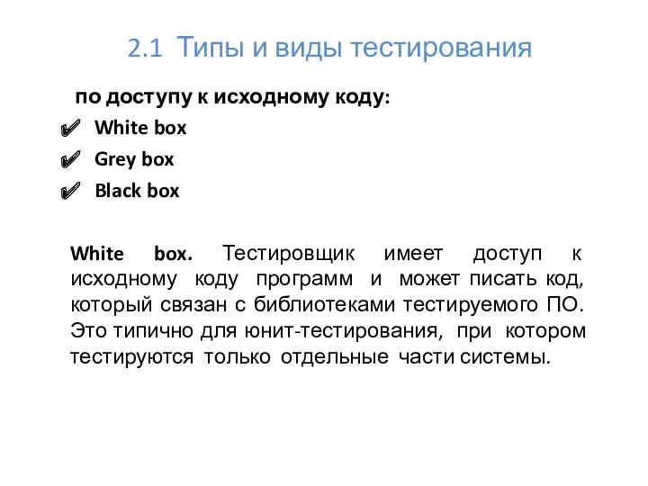 Типы и виды тестирования по доступу к исходному коду
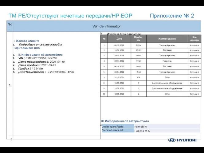 Коды неисправностей. Приложение Photos and description
 Типы алгоритмов. Алгоритмы с повторениями
 Современная криптография
 Шифрование с открытым ключом. Алгоритм RSA
 Adaptive libraries for multicore architectures with explicitly-managed memory hierarchies
 Криптографические методы защиты информации
 Внутренняя оптимизация
 Добро пожаловать в PowerPoint! 5 советов, которые помогут вам упростить работу
 Новые течения современной журналистики
 Встраивание видео в презентацию
 Особливості викладання інформатики
 Внеклассное мероприятие ИНФОРМ-БОЙ
 Алгоритмы и исполнители
 Применение ИКТ на уроках математики
 Configuration
 Пересечение множеств
 Рисуем мультфильм
 Голосовые мессенджеры
 Пути изучения английского языка с помощью сети интернет