- Hardware Configuration

Содержание
- 2. Hardware Configuration
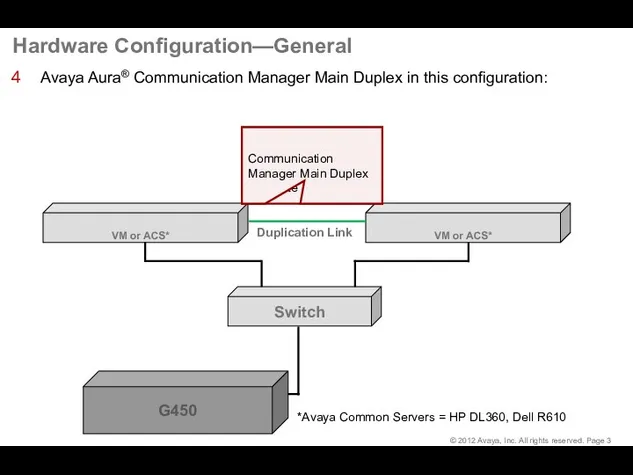
- 3. Hardware Configuration—General Avaya Aura® Communication Manager Main Duplex in this configuration: G450
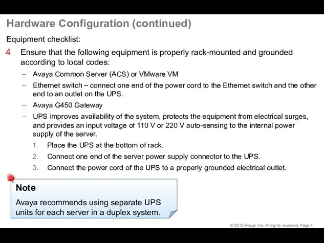
- 4. Hardware Configuration (continued) Equipment checklist: Ensure that the following equipment is properly rack-mounted and grounded according
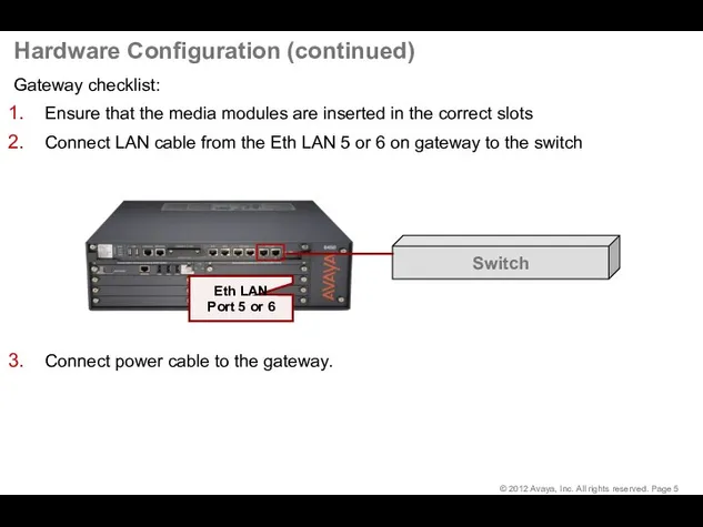
- 5. Hardware Configuration (continued) Gateway checklist: Ensure that the media modules are inserted in the correct slots
- 6. G450 Media Module Slot Assignments
- 7. Deployment of the CM OVA
- 8. Deploy the CM OVA At the end of this lesson, you should be able to: Identify
- 9. Deployment and Servers Virtualized Environment (VE) – Avaya and customer work together to enable the solution:
- 10. Planning and Configuration Ensure that you complete the following before deploying the Communication Manager open virtual
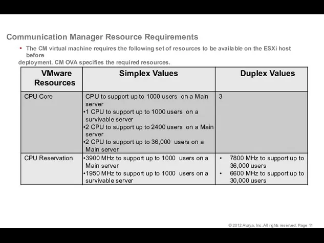
- 11. Communication Manager Resource Requirements The CM virtual machine requires the following set of resources to be
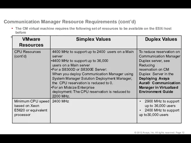
- 12. Communication Manager Resource Requirements (cont’d) The CM virtual machine requires the following set of resources to
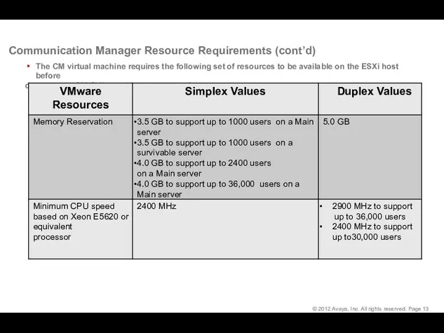
- 13. Communication Manager Resource Requirements (cont’d) The CM virtual machine requires the following set of resources to
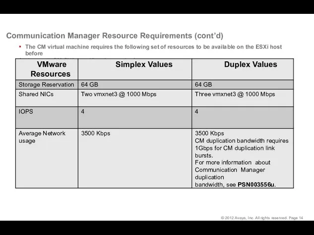
- 14. Communication Manager Resource Requirements (cont’d) The CM virtual machine requires the following set of resources to
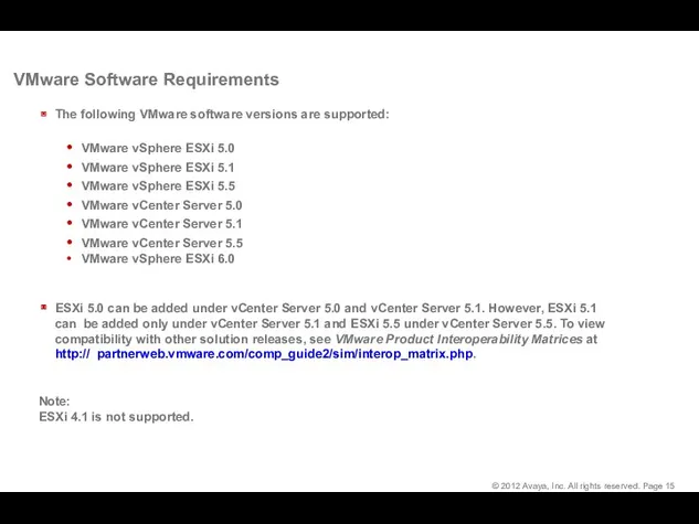
- 15. VMware Software Requirements The following VMware software versions are supported: VMware vSphere ESXi 5.0 VMware vSphere
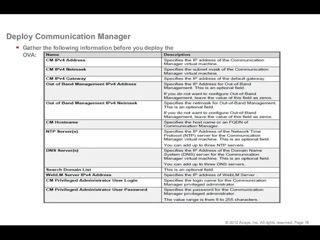
- 16. Deploy Communication Manager Gather the following information before you deploy the OVA:
- 17. Click Browse and provide the CM OVA file location and click Next: From File, click Deploy
- 18. Read the License Agreement and click Accept to accept the license, and then click Next: Deploy
- 19. Select a Deployment Configuration and click Next: Deploy Communication Manager (cont’d) In the Name field, type
- 20. Deploy Communication Manager (cont’d) Select the data store location to store the virtual machine files and
- 21. Deploy Communication Manager (cont’d) If you have multiple virtual machine networks in your environment you will
- 22. Deploy Communication Manager (cont’d) Management Network Settings (cont’d) Next the Management Network Settings page will be
- 23. Deploy Communication Manager (cont’d) Management Network Settings (cont’d) Scroll down to complete the remaining fields and
- 24. View the Deploying status: Deployment Completed Successfully Deploy Communication Manager (cont’d) Note : It is possible
- 25. Deploy Communication Manager (cont’d) Starting the Virtual Machine 1. The new virtual machine will be in
- 26. Communication Manager (CM) OVA Deployment - Duplex To deploy the Duplex OVA, install the Duplex OVA
- 27. Install the CM Main Duplex Launch another browser on your computer. Type the Communication Manager IP
- 28. Install the CM Main Duplex The Messages page indicates the last time that login was used.
- 29. Install the CM Main Duplex Select Server Configuration > Network Configuration to administer the network connections
- 30. Install the CM Main Duplex Complete the administration of eth1 at the bottom of the Network
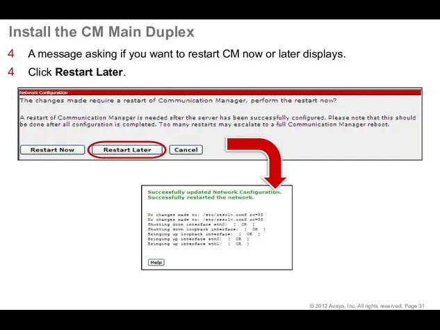
- 31. Install the CM Main Duplex A message asking if you want to restart CM now or
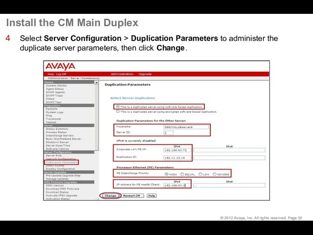
- 32. Install the CM Main Duplex Select Server Configuration > Duplication Parameters to administer the duplicate server
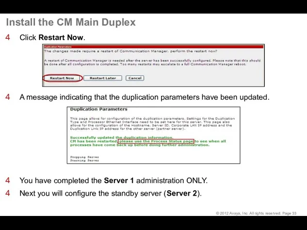
- 33. Install the CM Main Duplex Click Restart Now. A message indicating that the duplication parameters have
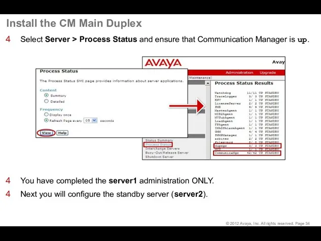
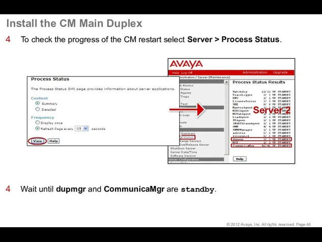
- 34. Install the CM Main Duplex Select Server > Process Status and ensure that Communication Manager is
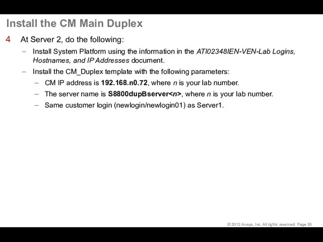
- 35. Install the CM Main Duplex At Server 2, do the following: Install System Platform using the
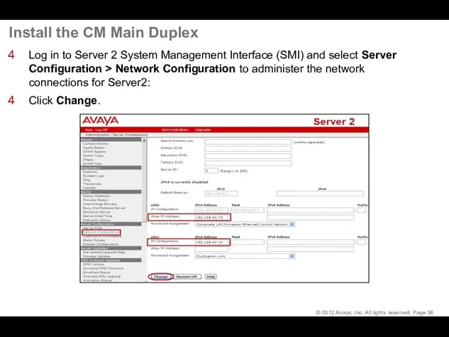
- 36. Install the CM Main Duplex Log in to Server 2 System Management Interface (SMI) and select
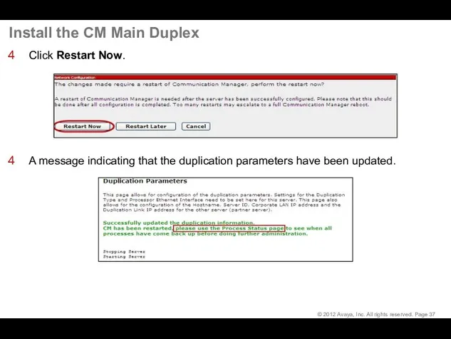
- 37. Install the CM Main Duplex Click Restart Now. A message indicating that the duplication parameters have
- 38. Install the CM Main Duplex At the SMI for server2 select Server Configuration > Duplication Parameters
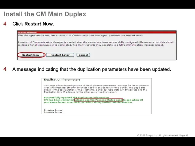
- 39. Install the CM Main Duplex Click Restart Now. A message indicating that the duplication parameters have
- 40. Install the CM Main Duplex To check the progress of the CM restart select Server >
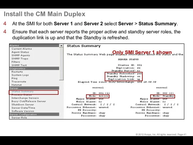
- 41. Install the CM Main Duplex At the SMI for both Server 1 and Server 2 select
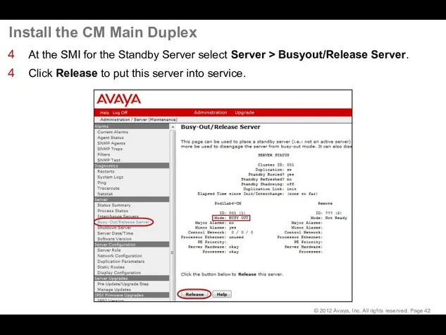
- 42. Install the CM Main Duplex At the SMI for the Standby Server select Server > Busyout/Release
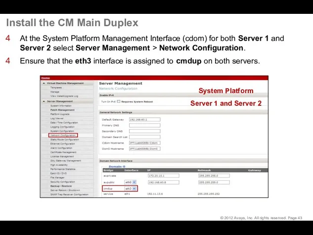
- 43. Install the CM Main Duplex At the System Platform Management Interface (cdom) for both Server 1
- 44. Install the License Files
- 45. Download License from PLDS
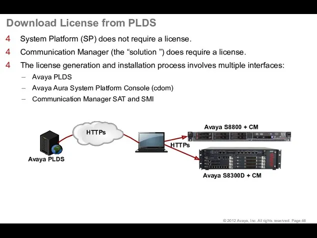
- 46. Download License from PLDS System Platform (SP) does not require a license. Communication Manager (the “solution
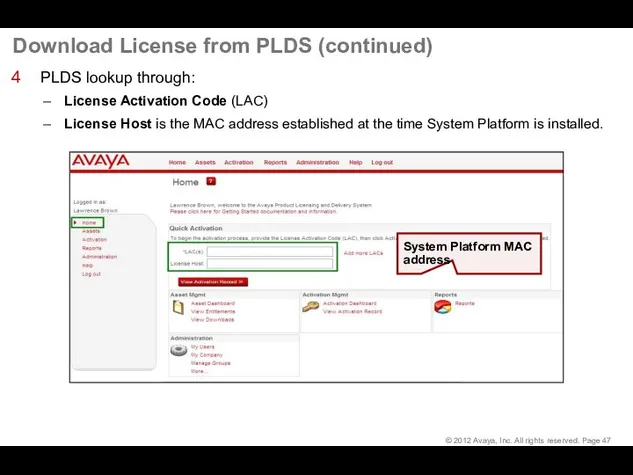
- 47. Download License from PLDS (continued) PLDS lookup through: License Activation Code (LAC) License Host is the
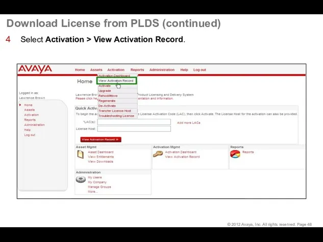
- 48. Download License from PLDS (continued) Select Activation > View Activation Record.
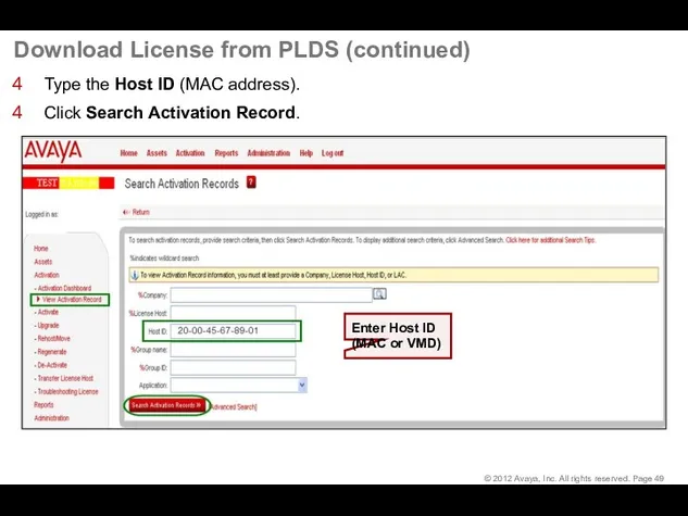
- 49. Download License from PLDS (continued) Type the Host ID (MAC address). Click Search Activation Record.
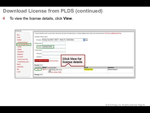
- 50. Download License from PLDS (continued) To view the license details, click View.
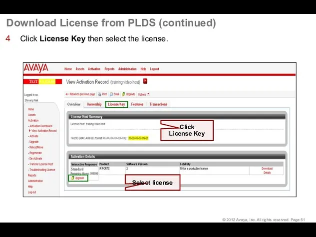
- 51. Download License from PLDS (continued) Click License Key then select the license.
- 52. Download License from PLDS (continued) Click Save to File. Save file to Service PC. Click Save
- 53. Install the License File
- 54. Install the License File Connect Service PC to Services port on server. Open a browser. Go
- 55. Install the License File (continued) The first time that you launch the Web License Manager you
- 56. Install the License File (continued) Select Install License. Browse to the license file location on the
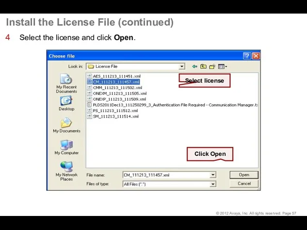
- 57. Install the License File (continued) Select the license and click Open.
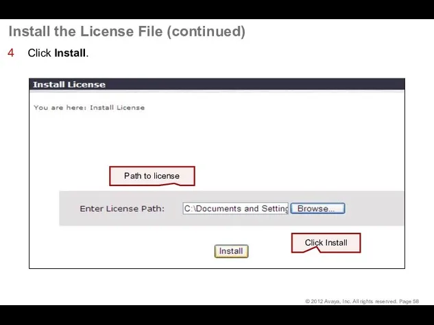
- 58. Install the License File (continued) Click Install. Path to license Click Install
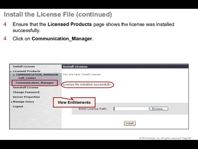
- 59. Install the License File (continued) Ensure that the Licensed Products page shows the license was installed
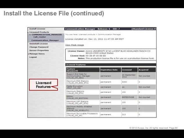
- 60. Install the License File (continued)
- 61. Complete Installation
- 62. Log in to Communication Manager
- 63. Save Communication Manager Translations Type save translation and press Enter to save changes to the system
- 64. Reset System 4 Type reset system 4 and press Enter to commit the updates to the
- 65. Configure G430/G450 Gateway
- 66. Log in to Gateway CLI
- 67. Log in to Gateway Command Line Interface (CLI) You can connect to the G450 Command Line
- 68. Log in to the Gateway CLI (continued) Log in to the gateway using HyperTerminal, PuTTY, or
- 69. Gateway Configuration
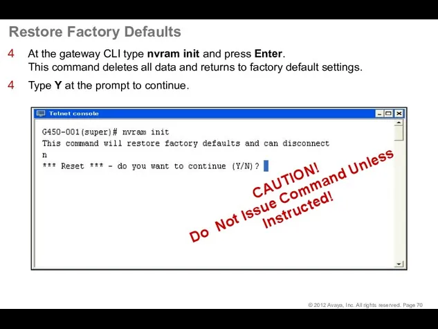
- 70. Restore Factory Defaults At the gateway CLI type nvram init and press Enter. This command deletes
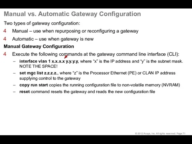
- 71. Manual vs. Automatic Gateway Configuration Two types of gateway configuration: Manual – use when repurposing or
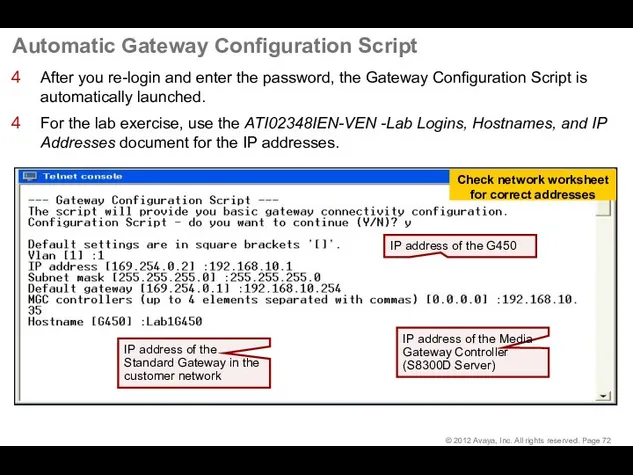
- 72. Automatic Gateway Configuration Script After you re-login and enter the password, the Gateway Configuration Script is
- 73. Automatic Gateway Configuration Script (continued) When the script has completed, save the new configuration by typing
- 74. Review Gateway Administration Use the show system command to review the gateway administration. Write down the
- 75. Save Gateway Administration Copy the configuration from the volatile to the non-volatile memory of the G450
- 76. Add the Gateway to CM Administration
- 77. Add Gateway to CM Administration At the CM SAT type add media-gateway 1 and press Enter.
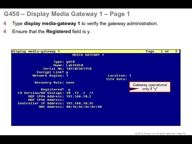
- 78. G450 – Display Media Gateway 1 – Page 1 Type display media-gateway 1 to verify the
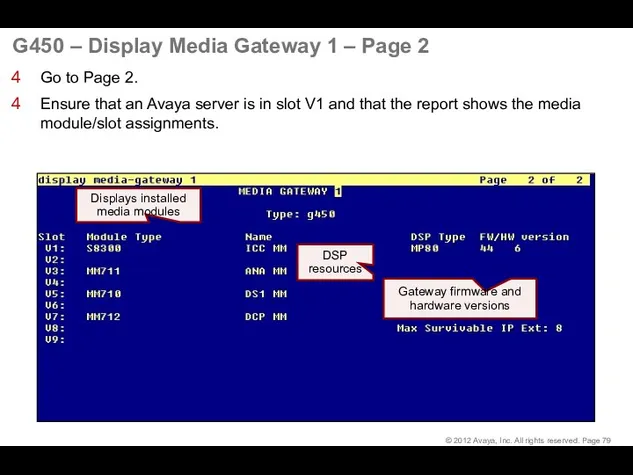
- 79. G450 – Display Media Gateway 1 – Page 2 Go to Page 2. Ensure that an
- 80. Configuring Communication Manager for AAMS connectivity © 2017 Avaya, Inc. All rights reserved.
- 81. Configuring Communication Manager for AAMS connectivity To configure Communication Manager for AAMS resources usage we
- 82. Configuring Communication Manager for AAMS connectivity Next we need to add a Signaling Group to
- 83. Configuring Communication Manager for AAMS connectivity And now we can add a media server to
- 84. Configuring Communication Manager for AAMS connectivity © 2017 Avaya, Inc. All rights reserved. After adding
- 85. Configure IPSI Circuit Pack
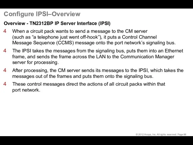
- 86. Configure IPSI–Overview Overview - TN2312BP IP Server Interface (IPSI) When a circuit pack wants to send
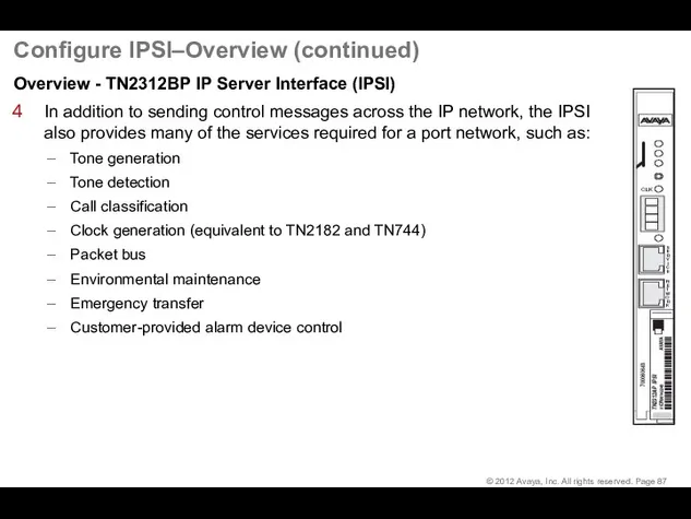
- 87. Configure IPSI–Overview (continued) Overview - TN2312BP IP Server Interface (IPSI) In addition to sending control messages
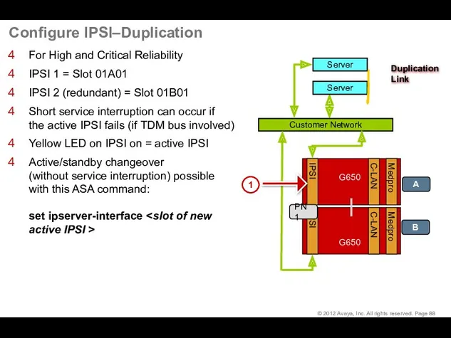
- 88. Configure IPSI–Duplication For High and Critical Reliability IPSI 1 = Slot 01A01 IPSI 2 (redundant) =
- 89. Configure IPSI–Access Open a command line interface on the Service PC (Start > Run > cmd).
- 90. Configure IPSI–Administration Commands must be entered in the full syntax as shown with no abbreviations nor
- 91. Configure IPSI–Administration (continued)
- 92. G650 Cabinet and Circuit Pack Administration in CM
- 93. Add Cabinet for Port Network 1 At the CM SAT type add cabinet 1 and press
- 94. Add Cabinet for Port Network 2 At the CM SAT type add cabinet 2 and press
- 95. Enable IPSI Control of Port Networks At the CM SAT type change system-parameters ip-server-interface and press
- 96. Administer IPSI 1 At the CM SAT type add ipserver-interface 1 and press Enter. Administer the
- 97. Administer IPSI 2 At the CM SAT type add ipserver-interface 2 and press Enter. Administer the
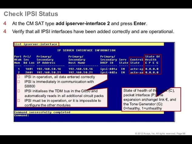
- 98. Check IPSI Status At the CM SAT type add ipserver-interface 2 and press Enter. Verify that
- 99. Enable Operation of IPSI Duplication At the CM SAT type change system-parameters duplication and press Enter.
- 100. Duplicated IPSI Administration in CM Go back to the IPSI interface 1 form and add the
- 101. Check IPSI Status At the CM SAT type list ipserver-interface and press Enter. Verify that the
- 102. Confirm System Configuration At the CM SAT type list configuration all and press Enter. Verify that
- 103. Administer Node Names IP Table At the CM SAT type change node-names ip and press Enter.
- 104. Look Up C-LAN Configuration At the CM SAT type list configuration circuit-pack TN799 and press Enter.
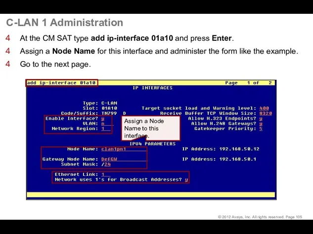
- 105. C-LAN 1 Administration At the CM SAT type add ip-interface 01a10 and press Enter. Assign a
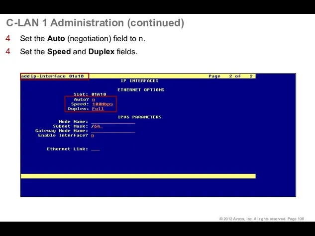
- 106. C-LAN 1 Administration (continued) Set the Auto (negotiation) field to n. Set the Speed and Duplex
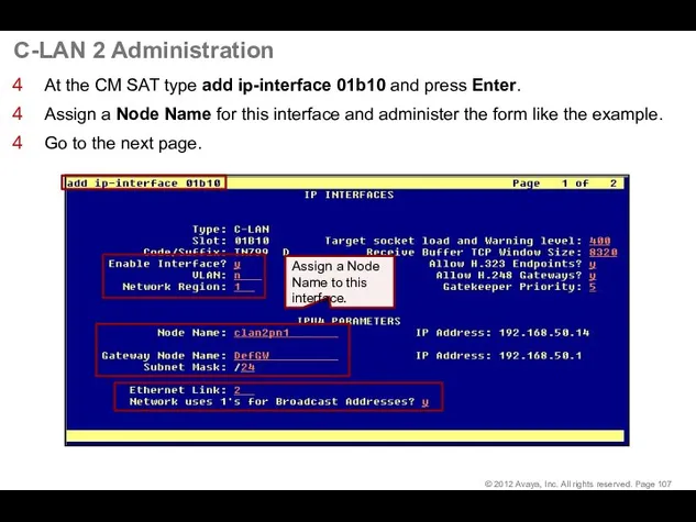
- 107. C-LAN 2 Administration At the CM SAT type add ip-interface 01b10 and press Enter. Assign a
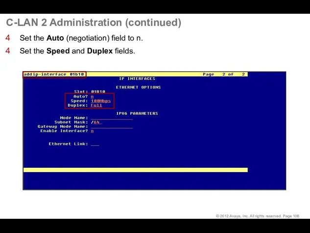
- 108. C-LAN 2 Administration (continued) Set the Auto (negotiation) field to n. Set the Speed and Duplex
- 109. C-LAN 3 Administration At the CM SAT type add ip-interface 02a10 and press Enter. Assign a
- 110. C-LAN 3 Administration (continued) Set the Auto (negotiation) field to n. Set the Speed and Duplex
- 111. Verify C-LAN Status At the CM SAT type status clan-all and press Enter. Verify that all
- 112. List Configuration for MedPro At the CM SAT type list configuration circuit-pack TN2302 and press Enter.
- 113. List Configuration for Media Resource 320 At the CM SAT type list configuration circuit-pack TN2602 and
- 114. Media Resource 1 Administration At the SAT type add ip-interface 01a12 and press Enter. Set the
- 115. Media Resource 1 Administration (continued) Set the Auto (negotiation) field to n. Set the Speed and
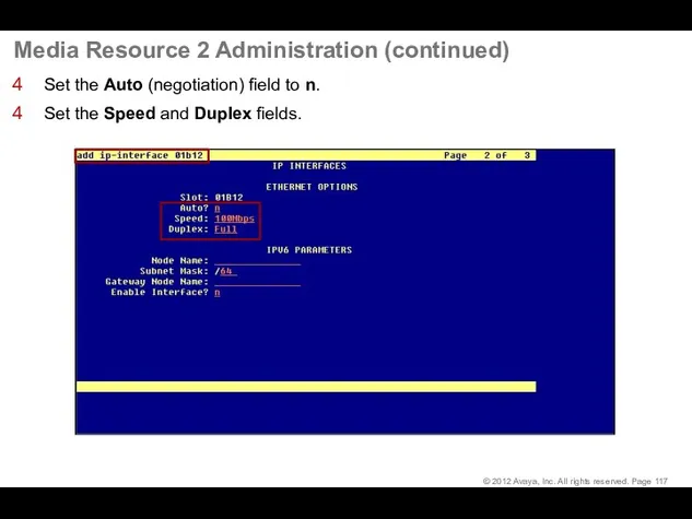
- 116. Media Resource 2 Administration At the SAT type add ip-interface 01b12 and press Enter. Set the
- 117. Media Resource 2 Administration (continued) Set the Auto (negotiation) field to n. Set the Speed and
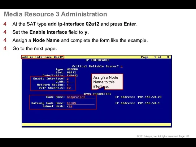
- 118. Media Resource 3 Administration At the SAT type add ip-interface 02a12 and press Enter. Set the
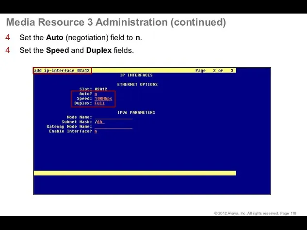
- 119. Media Resource 3 Administration (continued) Set the Auto (negotiation) field to n. Set the Speed and
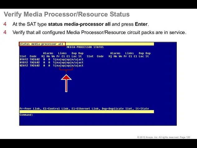
- 120. Verify Media Processor/Resource Status At the SAT type status media-processor all and press Enter. Verify that
- 121. Make a Test Call
- 122. Administer CM Endpoints
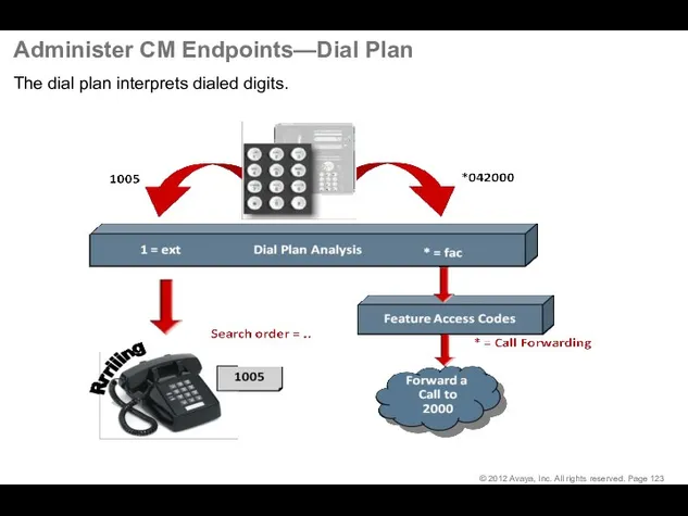
- 123. Administer CM Endpoints—Dial Plan The dial plan interprets dialed digits.
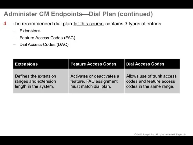
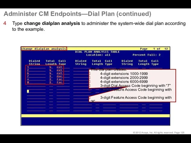
- 124. Administer CM Endpoints—Dial Plan (continued) The recommended dial plan for this course contains 3 types of
- 125. Administer CM Endpoints—Dial Plan (continued) Type change dialplan analysis to administer the system-wide dial plan according
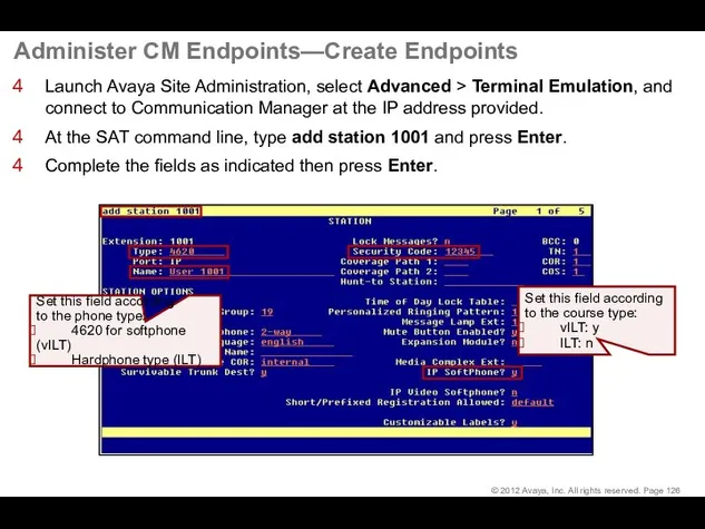
- 126. Administer CM Endpoints—Create Endpoints Launch Avaya Site Administration, select Advanced > Terminal Emulation, and connect to
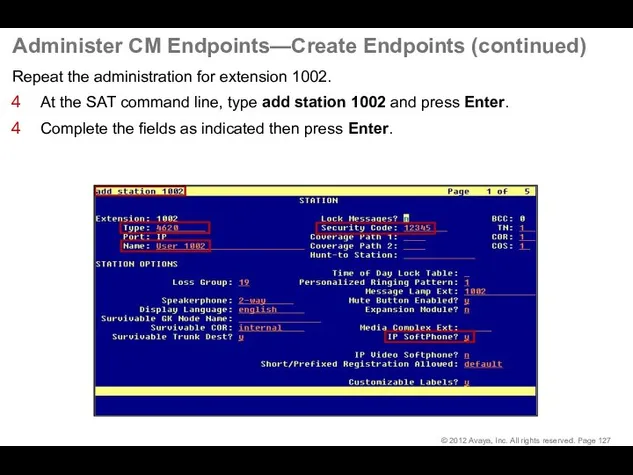
- 127. Administer CM Endpoints—Create Endpoints (continued) Repeat the administration for extension 1002. At the SAT command line,
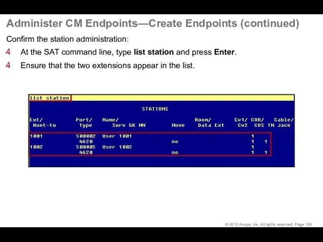
- 128. Administer CM Endpoints—Create Endpoints (continued) Confirm the station administration: At the SAT command line, type list
- 129. Administer one-X® Communicator
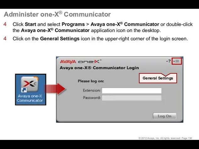
- 130. Administer one-X® Communicator Click Start and select Programs > Avaya one-X® Communicator or double-click the Avaya
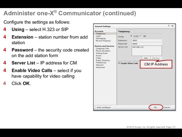
- 131. Administer one-X® Communicator (continued) Configure the settings as follows: Using – select H.323 or SIP Extension
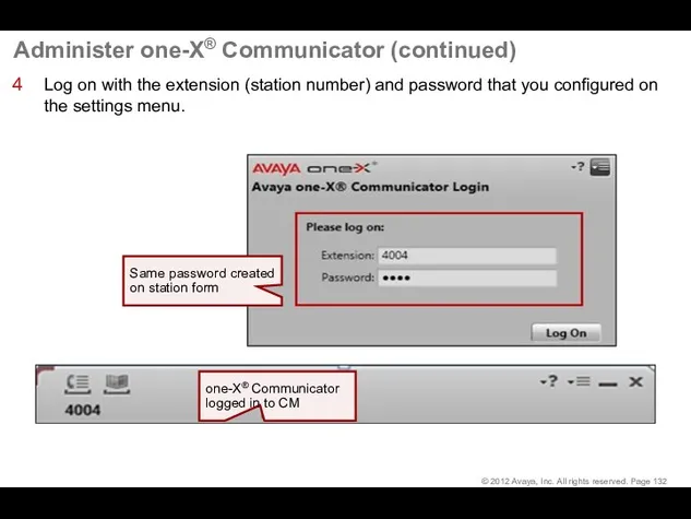
- 132. Administer one-X® Communicator (continued) Log on with the extension (station number) and password that you configured
- 133. Verify IP Telephone Registration At the Avaya Site Administration window, type list registered-ip-stations and press Enter.
- 134. Dial the Test Call
- 135. Dial the Test Call Type the number of the extension that you want to call in
- 136. Dial the Test Call (continued) The example below shows a call from extension 4004 to extension
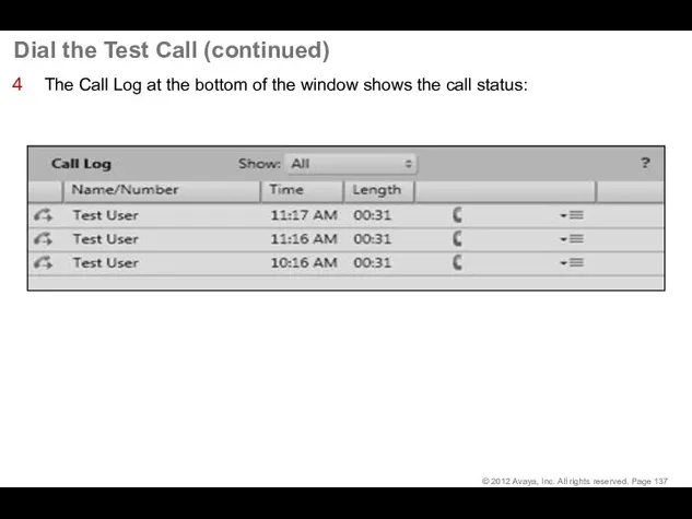
- 137. Dial the Test Call (continued) The Call Log at the bottom of the window shows the
- 139. Скачать презентацию
Hardware Configuration
Hardware Configuration
Hardware Configuration—General
Avaya Aura® Communication Manager Main Duplex in this configuration:
G450
Hardware Configuration—General
Avaya Aura® Communication Manager Main Duplex in this configuration:
G450
Hardware Configuration (continued)
Equipment checklist:
Ensure that the following equipment is properly rack-mounted
Hardware Configuration (continued)
Equipment checklist:
Ensure that the following equipment is properly rack-mounted
Hardware Configuration (continued)
Gateway checklist:
Ensure that the media modules are inserted in
Hardware Configuration (continued)
Gateway checklist:
Ensure that the media modules are inserted in
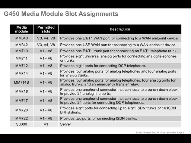
G450 Media Module Slot Assignments
G450 Media Module Slot Assignments

Deployment of the CM OVA
Deployment of the CM OVA
Deploy the CM OVA
At the end of this lesson, you should
Deploy the CM OVA
At the end of this lesson, you should
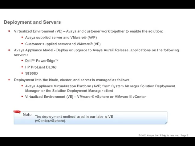
Deployment and Servers
Virtualized Environment (VE) – Avaya and customer work together
Deployment and Servers
Virtualized Environment (VE) – Avaya and customer work together
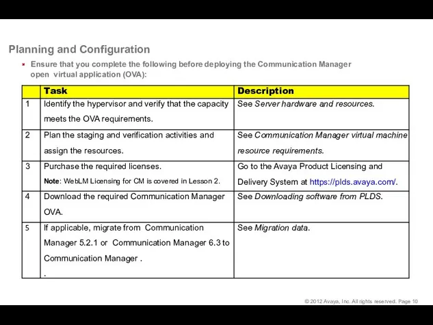
Planning and Configuration
Ensure that you complete the following before deploying the
Planning and Configuration
Ensure that you complete the following before deploying the
Communication Manager Resource Requirements
The CM virtual machine requires the following set
Communication Manager Resource Requirements
The CM virtual machine requires the following set
Communication Manager Resource Requirements (cont’d)
The CM virtual machine requires the following
Communication Manager Resource Requirements (cont’d)
The CM virtual machine requires the following
Communication Manager Resource Requirements (cont’d)
The CM virtual machine requires the following
Communication Manager Resource Requirements (cont’d)
The CM virtual machine requires the following
Communication Manager Resource Requirements (cont’d)
The CM virtual machine requires the following
Communication Manager Resource Requirements (cont’d)
The CM virtual machine requires the following
VMware Software Requirements
The following VMware software versions are supported:
VMware vSphere ESXi
VMware Software Requirements
The following VMware software versions are supported:
VMware vSphere ESXi
Deploy Communication Manager
Gather the following information before you deploy the
Deploy Communication Manager
Gather the following information before you deploy the
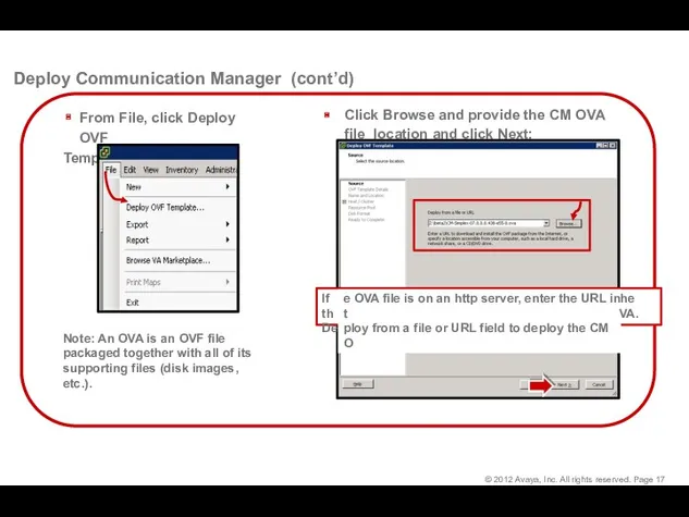
Click Browse and provide the CM OVA file location and click
Click Browse and provide the CM OVA file location and click
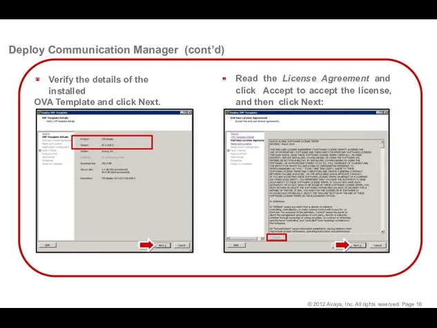
Read the License Agreement and click Accept to accept the license,
Read the License Agreement and click Accept to accept the license,
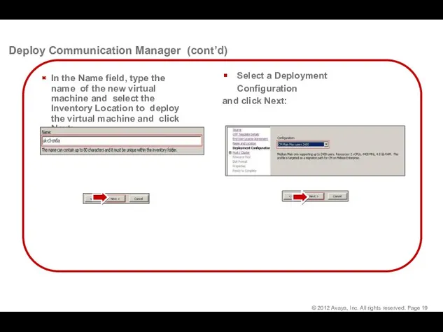
Select a Deployment Configuration
and click Next:
Deploy Communication Manager (cont’d)
In the Name
Select a Deployment Configuration
and click Next:
Deploy Communication Manager (cont’d)
In the Name
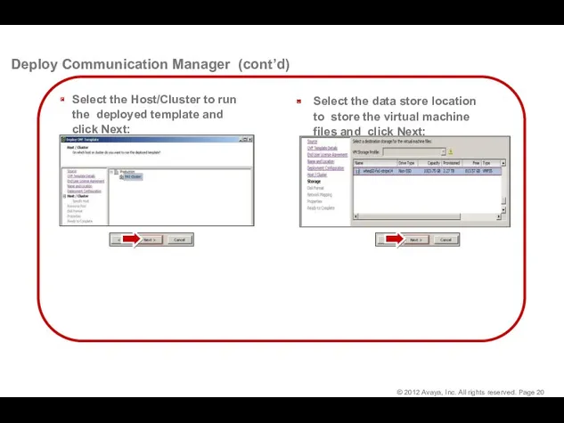
Deploy Communication Manager (cont’d)
Select the data store location to store the
Deploy Communication Manager (cont’d)
Select the data store location to store the
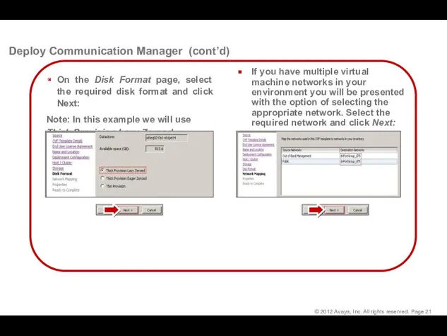
Deploy Communication Manager (cont’d)
If you have multiple virtual machine networks in
Deploy Communication Manager (cont’d)
If you have multiple virtual machine networks in
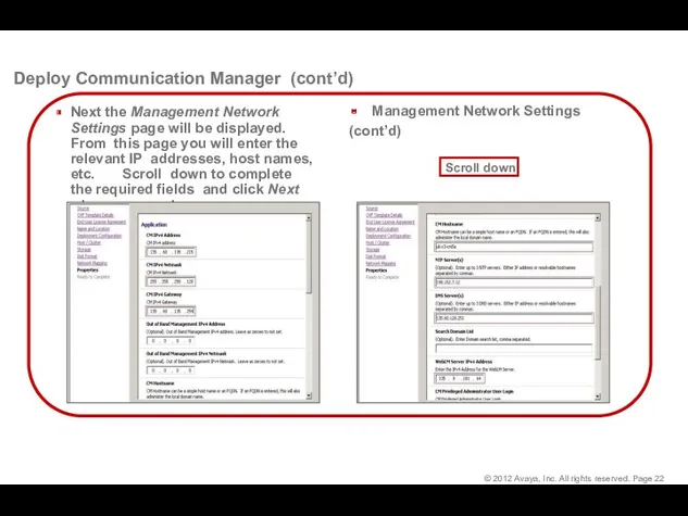
Deploy Communication Manager (cont’d)
Management Network Settings
(cont’d)
Next the Management Network Settings page
Deploy Communication Manager (cont’d)
Management Network Settings
(cont’d)
Next the Management Network Settings page
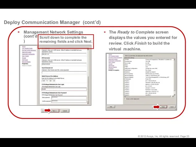
Deploy Communication Manager (cont’d)
Management Network Settings
(cont’d)
Scroll down to complete the
remaining fields
Deploy Communication Manager (cont’d)
Management Network Settings
(cont’d)
Scroll down to complete the
remaining fields
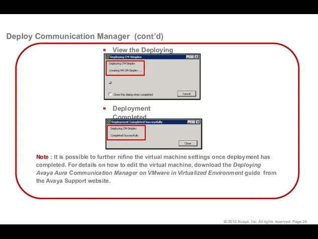
View the Deploying status:
Deployment Completed Successfully
Deploy Communication Manager (cont’d)
Note : It
View the Deploying status:
Deployment Completed Successfully
Deploy Communication Manager (cont’d)
Note : It
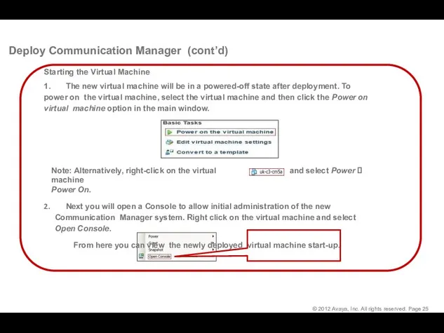
Deploy Communication Manager (cont’d)
Starting the Virtual Machine
1. The new virtual machine will
Deploy Communication Manager (cont’d)
Starting the Virtual Machine
1. The new virtual machine will
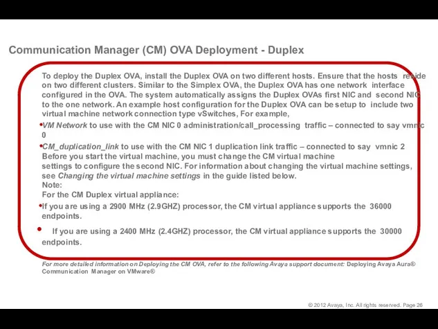
Communication Manager (CM) OVA Deployment - Duplex
To deploy the Duplex OVA,
Communication Manager (CM) OVA Deployment - Duplex
To deploy the Duplex OVA,
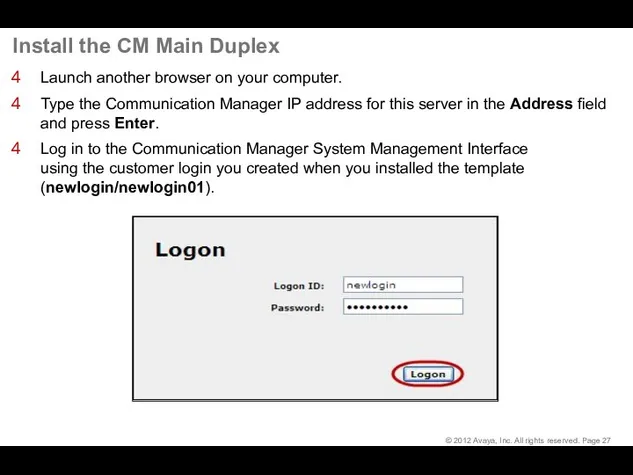
Install the CM Main Duplex
Launch another browser on your computer.
Type
Install the CM Main Duplex
Launch another browser on your computer.
Type
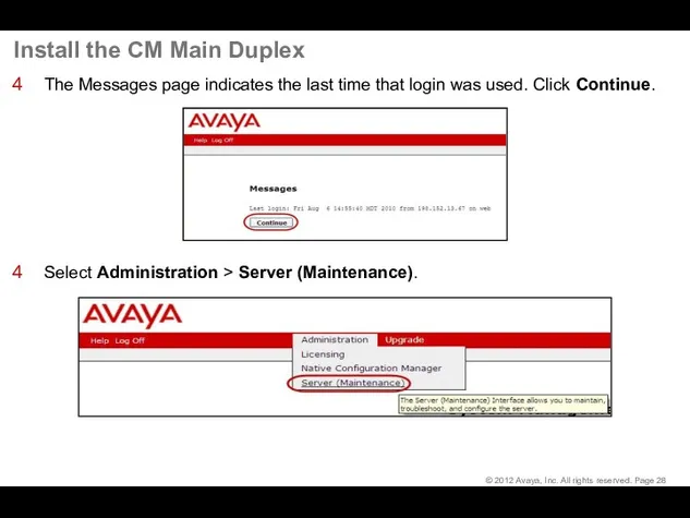
Install the CM Main Duplex
The Messages page indicates the last
Install the CM Main Duplex
The Messages page indicates the last
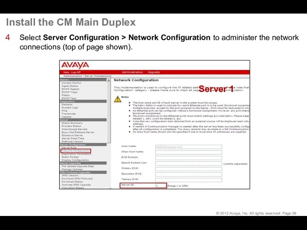
Install the CM Main Duplex
Select Server Configuration > Network Configuration
Install the CM Main Duplex
Select Server Configuration > Network Configuration
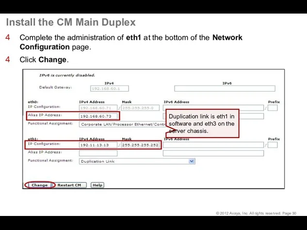
Install the CM Main Duplex
Complete the administration of eth1 at
Install the CM Main Duplex
Complete the administration of eth1 at
Install the CM Main Duplex
A message asking if you want
Install the CM Main Duplex
A message asking if you want
Install the CM Main Duplex
Select Server Configuration > Duplication Parameters
Install the CM Main Duplex
Select Server Configuration > Duplication Parameters
Install the CM Main Duplex
Click Restart Now.
A message indicating that
Install the CM Main Duplex
Click Restart Now.
A message indicating that
Install the CM Main Duplex
Select Server > Process Status and
Install the CM Main Duplex
Select Server > Process Status and
Install the CM Main Duplex
At Server 2, do the following:
Install
Install the CM Main Duplex
At Server 2, do the following:
Install
Install the CM Main Duplex
Log in to Server 2 System
Install the CM Main Duplex
Log in to Server 2 System
Install the CM Main Duplex
Click Restart Now.
A message indicating that
Install the CM Main Duplex
Click Restart Now.
A message indicating that

Install the CM Main Duplex
At the SMI for server2 select
Install the CM Main Duplex
At the SMI for server2 select
Install the CM Main Duplex
Click Restart Now.
A message indicating that
Install the CM Main Duplex
Click Restart Now.
A message indicating that
Install the CM Main Duplex
To check the progress of the
Install the CM Main Duplex
To check the progress of the
Install the CM Main Duplex
At the SMI for both Server
Install the CM Main Duplex
At the SMI for both Server
Install the CM Main Duplex
At the SMI for the Standby
Install the CM Main Duplex
At the SMI for the Standby
Install the CM Main Duplex
At the System Platform Management Interface
Install the CM Main Duplex
At the System Platform Management Interface
Install the License Files
Install the License Files
Download License from PLDS
Download License from PLDS
Download License from PLDS
System Platform (SP) does not require a license.
Communication
Download License from PLDS
System Platform (SP) does not require a license.
Communication
Download License from PLDS (continued)
PLDS lookup through:
License Activation Code (LAC)
License Host
Download License from PLDS (continued)
PLDS lookup through:
License Activation Code (LAC)
License Host
Download License from PLDS (continued)
Select Activation > View Activation Record.
Download License from PLDS (continued)
Select Activation > View Activation Record.
Download License from PLDS (continued)
Type the Host ID (MAC address).
Click Search
Download License from PLDS (continued)
Type the Host ID (MAC address).
Click Search
Download License from PLDS (continued)
To view the license details, click View.
Download License from PLDS (continued)
To view the license details, click View.
Download License from PLDS (continued)
Click License Key then select the license.
Download License from PLDS (continued)
Click License Key then select the license.
Download License from PLDS (continued)
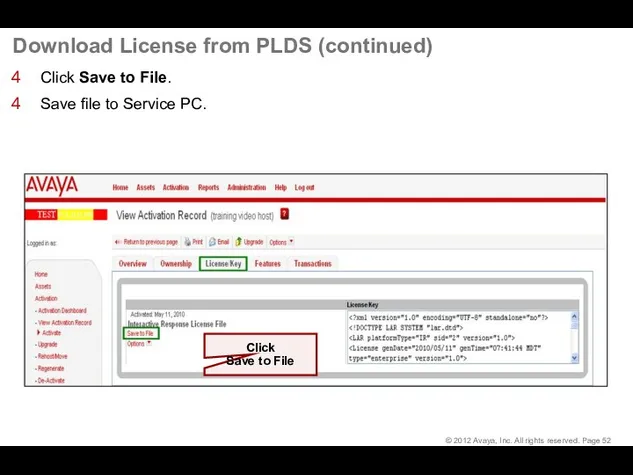
Click Save to File.
Save file to Service
Download License from PLDS (continued)
Click Save to File.
Save file to Service

Install the License File
Install the License File
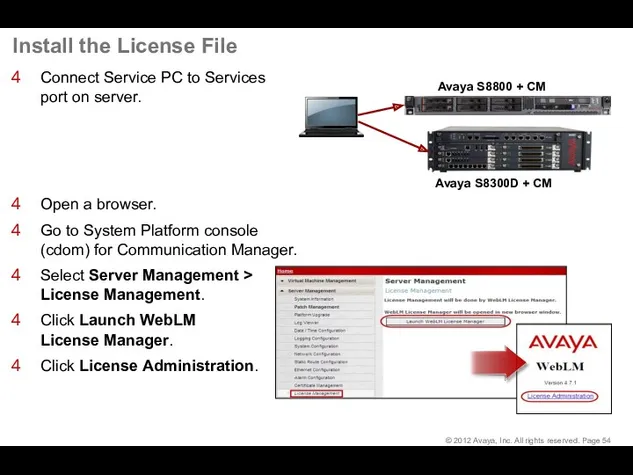
Install the License File
Connect Service PC to Services
port on server.
Open
Install the License File
Connect Service PC to Services
port on server.
Open
Install the License File (continued)
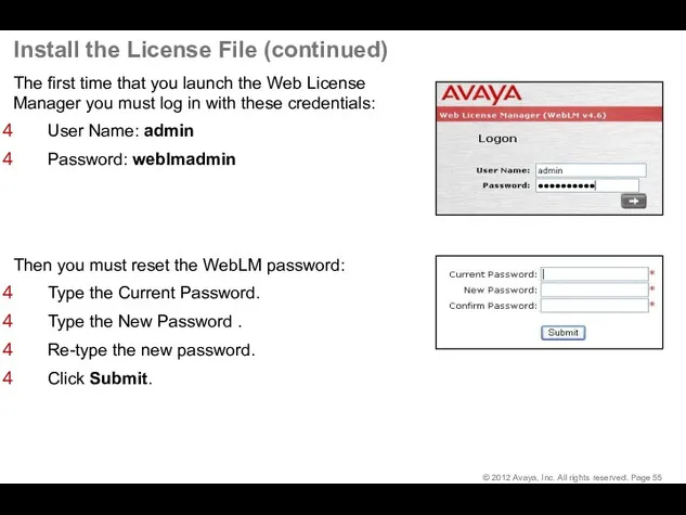
The first time that you launch the
Install the License File (continued)
The first time that you launch the
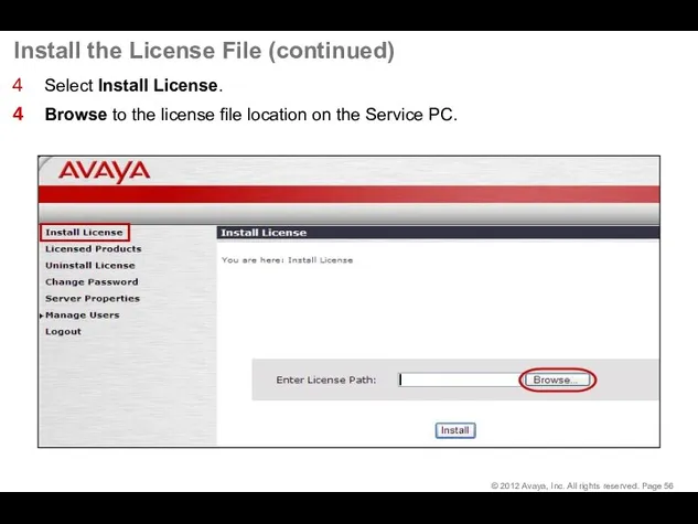
Install the License File (continued)
Select Install License.
Browse to the license file
Install the License File (continued)
Select Install License.
Browse to the license file
Install the License File (continued)
Select the license and click Open.
Install the License File (continued)
Select the license and click Open.
Install the License File (continued)
Click Install.
Path to license
Click Install
Install the License File (continued)
Click Install.
Path to license
Click Install
Install the License File (continued)
Ensure that the Licensed Products page shows
Install the License File (continued)
Ensure that the Licensed Products page shows
Install the License File (continued)
Install the License File (continued)
Complete Installation
Complete Installation
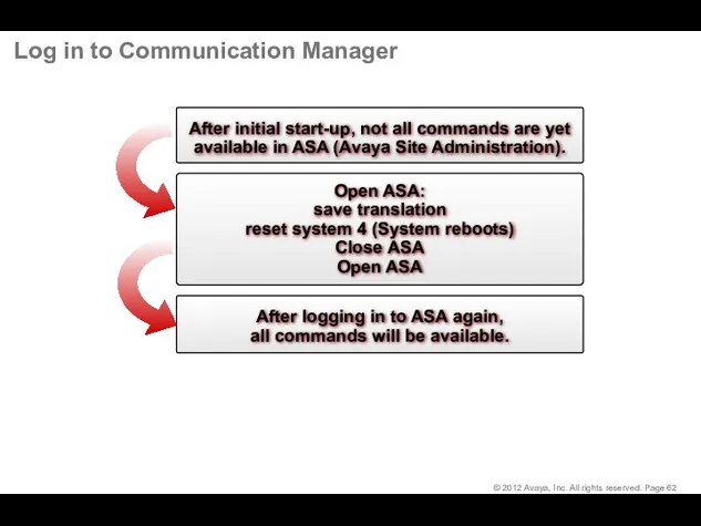
Log in to Communication Manager
Log in to Communication Manager
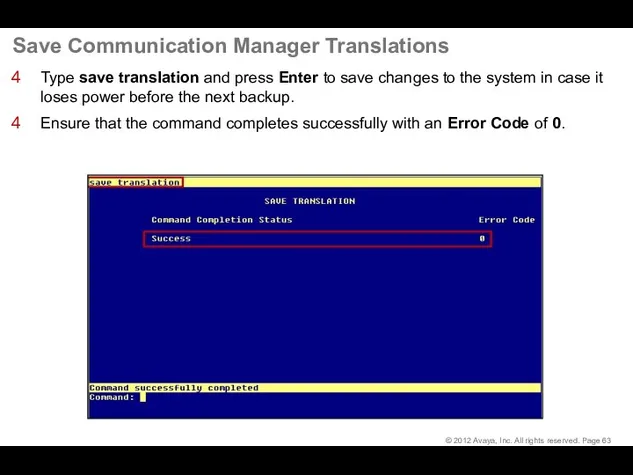
Save Communication Manager Translations
Type save translation and press Enter to save
Save Communication Manager Translations
Type save translation and press Enter to save
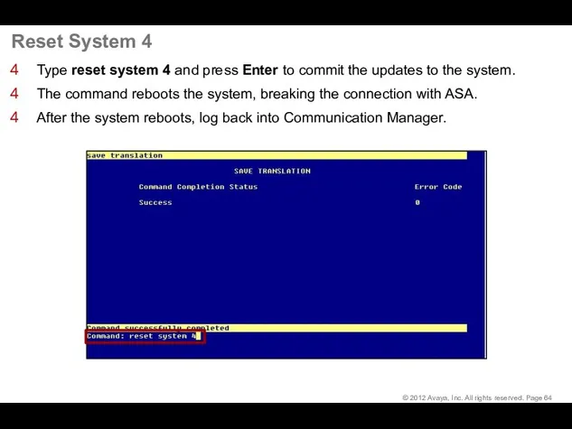
Reset System 4
Type reset system 4 and press Enter to commit
Reset System 4
Type reset system 4 and press Enter to commit
Configure G430/G450 Gateway
Configure G430/G450 Gateway
Log in to Gateway CLI
Log in to Gateway CLI
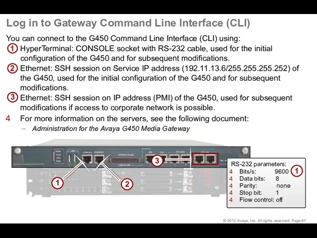
Log in to Gateway Command Line Interface (CLI)
You can connect to
Log in to Gateway Command Line Interface (CLI)
You can connect to
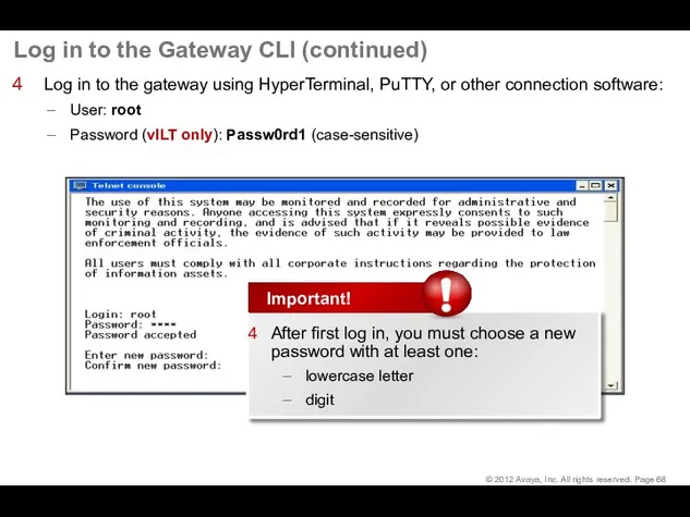
Log in to the Gateway CLI (continued)
Log in to the gateway
Log in to the Gateway CLI (continued)
Log in to the gateway
Gateway Configuration
Gateway Configuration
Restore Factory Defaults
At the gateway CLI type nvram init and press
Restore Factory Defaults
At the gateway CLI type nvram init and press
Manual vs. Automatic Gateway Configuration
Two types of gateway configuration:
Manual – use
Manual vs. Automatic Gateway Configuration
Two types of gateway configuration:
Manual – use
Automatic Gateway Configuration Script
After you re-login and enter the password, the
Automatic Gateway Configuration Script
After you re-login and enter the password, the
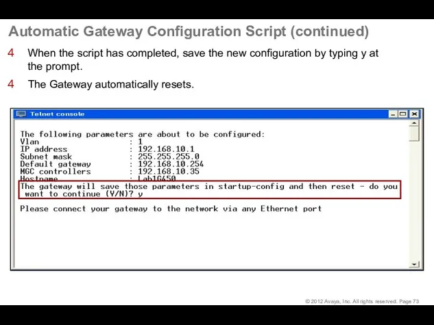
Automatic Gateway Configuration Script (continued)
When the script has completed, save the
Automatic Gateway Configuration Script (continued)
When the script has completed, save the
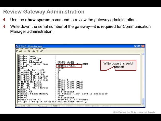
Review Gateway Administration
Use the show system command to review the gateway
Review Gateway Administration
Use the show system command to review the gateway
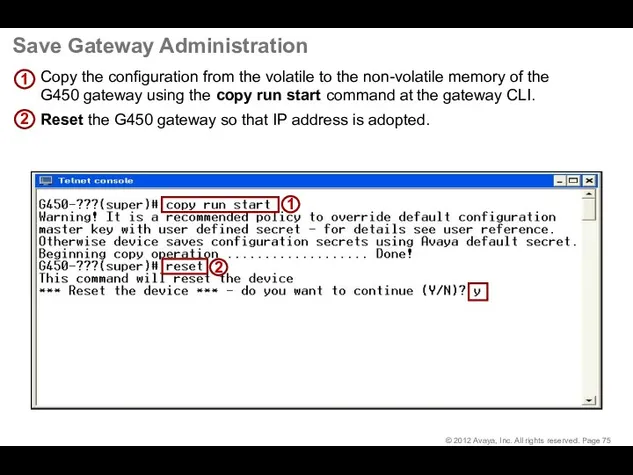
Save Gateway Administration
Copy the configuration from the volatile to the non-volatile
Save Gateway Administration
Copy the configuration from the volatile to the non-volatile
Add the Gateway to CM Administration
Add the Gateway to CM Administration
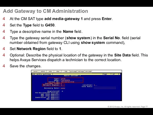
Add Gateway to CM Administration
At the CM SAT type add media-gateway
Add Gateway to CM Administration
At the CM SAT type add media-gateway
G450 – Display Media Gateway 1 – Page 1
Type display media-gateway
G450 – Display Media Gateway 1 – Page 1
Type display media-gateway
G450 – Display Media Gateway 1 – Page 2
Go to Page
G450 – Display Media Gateway 1 – Page 2
Go to Page
Configuring Communication Manager for AAMS connectivity
© 2017 Avaya, Inc. All rights
Configuring Communication Manager for AAMS connectivity
© 2017 Avaya, Inc. All rights
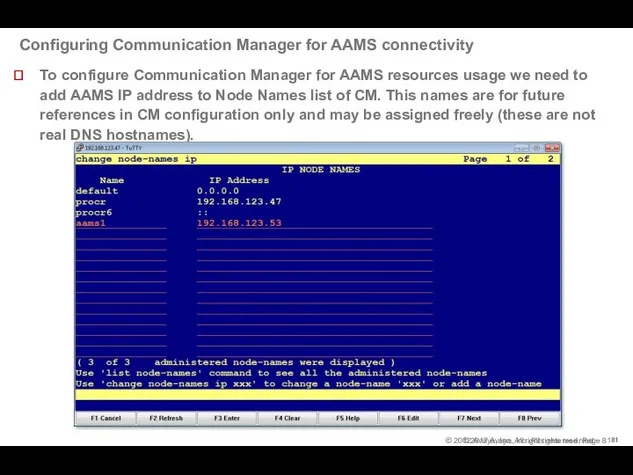
Configuring Communication Manager for AAMS connectivity
To configure Communication Manager for AAMS
Configuring Communication Manager for AAMS connectivity
To configure Communication Manager for AAMS
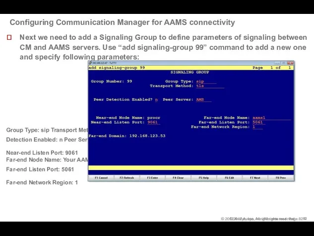
Configuring Communication Manager for AAMS connectivity
Next we need to add a
Configuring Communication Manager for AAMS connectivity
Next we need to add a
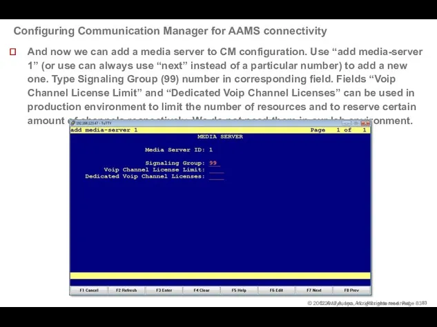
Configuring Communication Manager for AAMS connectivity
And now we can add a
Configuring Communication Manager for AAMS connectivity
And now we can add a
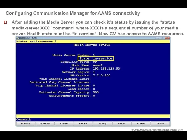
Configuring Communication Manager for AAMS connectivity
© 2017 Avaya, Inc. All rights
Configuring Communication Manager for AAMS connectivity
© 2017 Avaya, Inc. All rights
Configure IPSI Circuit Pack
Configure IPSI Circuit Pack
Configure IPSI–Overview
Overview - TN2312BP IP Server Interface (IPSI)
When a circuit
Configure IPSI–Overview
Overview - TN2312BP IP Server Interface (IPSI)
When a circuit
Configure IPSI–Overview (continued)
Overview - TN2312BP IP Server Interface (IPSI)
In addition
Configure IPSI–Overview (continued)
Overview - TN2312BP IP Server Interface (IPSI)
In addition
Configure IPSI–Duplication
For High and Critical Reliability
IPSI 1 = Slot 01A01
IPSI 2
Configure IPSI–Duplication
For High and Critical Reliability
IPSI 1 = Slot 01A01
IPSI 2
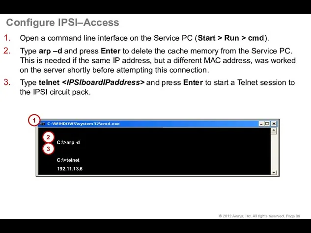
Configure IPSI–Access
Open a command line interface on the Service PC (Start
Configure IPSI–Access
Open a command line interface on the Service PC (Start
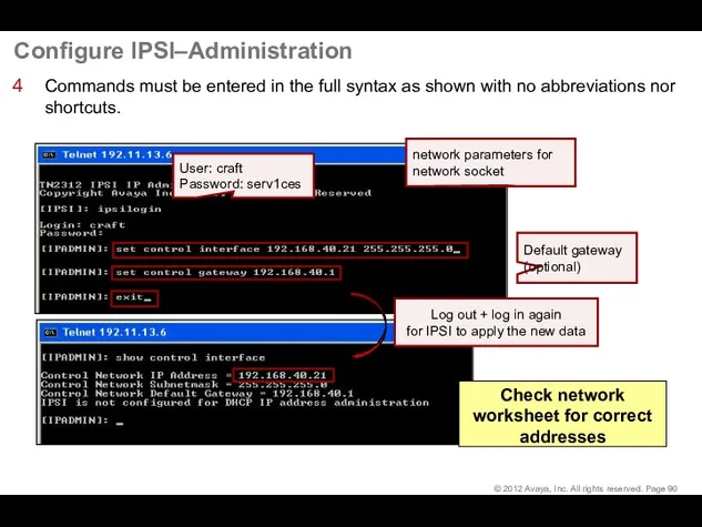
Configure IPSI–Administration
Commands must be entered in the full syntax as shown
Configure IPSI–Administration
Commands must be entered in the full syntax as shown
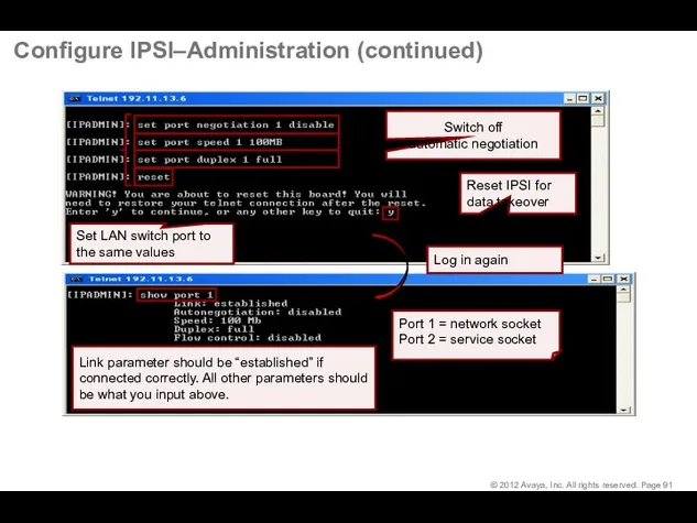
Configure IPSI–Administration (continued)
Configure IPSI–Administration (continued)
G650 Cabinet and Circuit Pack Administration in CM
G650 Cabinet and Circuit Pack Administration in CM
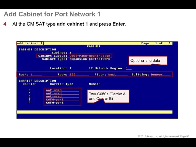
Add Cabinet for Port Network 1
At the CM SAT type add
Add Cabinet for Port Network 1
At the CM SAT type add
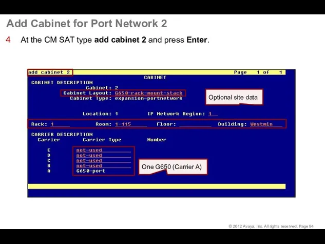
Add Cabinet for Port Network 2
At the CM SAT type add
Add Cabinet for Port Network 2
At the CM SAT type add
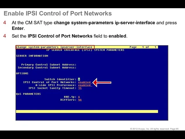
Enable IPSI Control of Port Networks
At the CM SAT type change
Enable IPSI Control of Port Networks
At the CM SAT type change
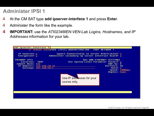
Administer IPSI 1
At the CM SAT type add ipserver-interface 1 and
Administer IPSI 1
At the CM SAT type add ipserver-interface 1 and
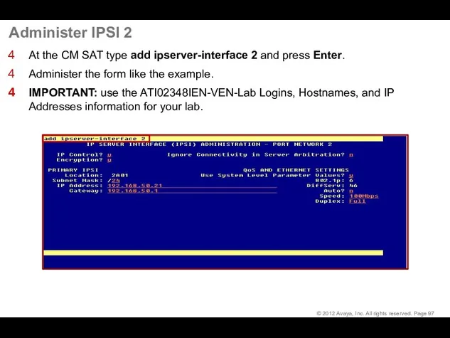
Administer IPSI 2
At the CM SAT type add ipserver-interface 2 and
Administer IPSI 2
At the CM SAT type add ipserver-interface 2 and
Check IPSI Status
At the CM SAT type add ipserver-interface 2 and
Check IPSI Status
At the CM SAT type add ipserver-interface 2 and
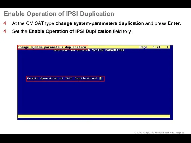
Enable Operation of IPSI Duplication
At the CM SAT type change system-parameters
Enable Operation of IPSI Duplication
At the CM SAT type change system-parameters
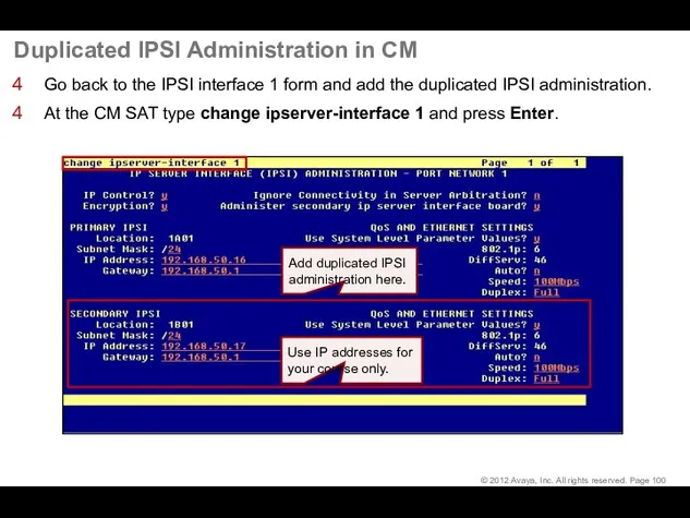
Duplicated IPSI Administration in CM
Go back to the IPSI interface 1
Duplicated IPSI Administration in CM
Go back to the IPSI interface 1
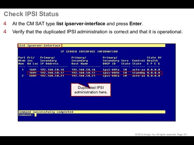
Check IPSI Status
At the CM SAT type list ipserver-interface and press
Check IPSI Status
At the CM SAT type list ipserver-interface and press
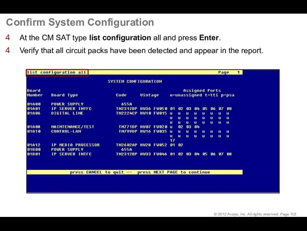
Confirm System Configuration
At the CM SAT type list configuration all and
Confirm System Configuration
At the CM SAT type list configuration all and
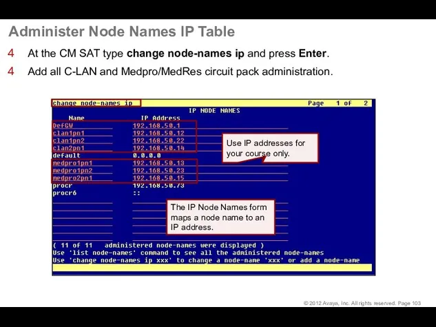
Administer Node Names IP Table
At the CM SAT type change node-names
Administer Node Names IP Table
At the CM SAT type change node-names
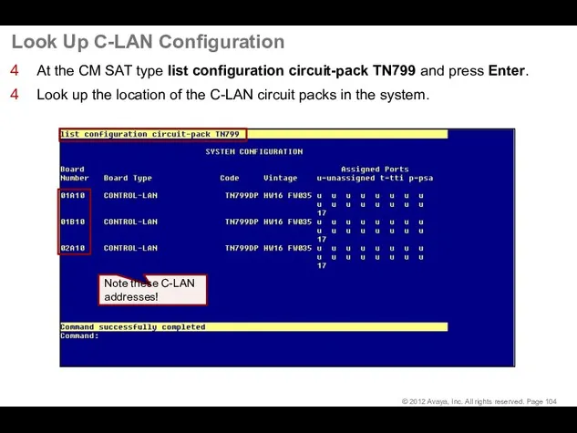
Look Up C-LAN Configuration
At the CM SAT type list configuration circuit-pack
Look Up C-LAN Configuration
At the CM SAT type list configuration circuit-pack
C-LAN 1 Administration
At the CM SAT type add ip-interface 01a10 and
C-LAN 1 Administration
At the CM SAT type add ip-interface 01a10 and
C-LAN 1 Administration (continued)
Set the Auto (negotiation) field to n.
Set the
C-LAN 1 Administration (continued)
Set the Auto (negotiation) field to n.
Set the
C-LAN 2 Administration
At the CM SAT type add ip-interface 01b10 and
C-LAN 2 Administration
At the CM SAT type add ip-interface 01b10 and
C-LAN 2 Administration (continued)
Set the Auto (negotiation) field to n.
Set the
C-LAN 2 Administration (continued)
Set the Auto (negotiation) field to n.
Set the
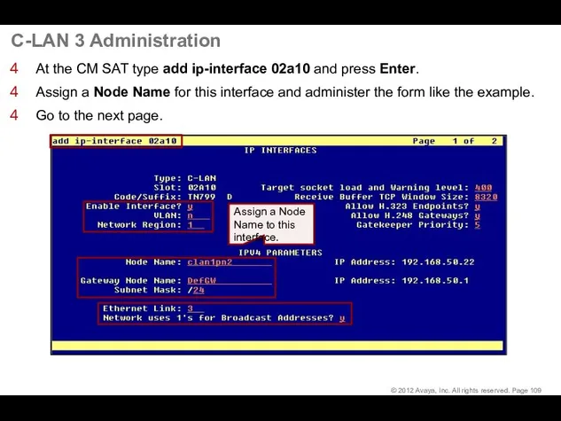
C-LAN 3 Administration
At the CM SAT type add ip-interface 02a10 and
C-LAN 3 Administration
At the CM SAT type add ip-interface 02a10 and
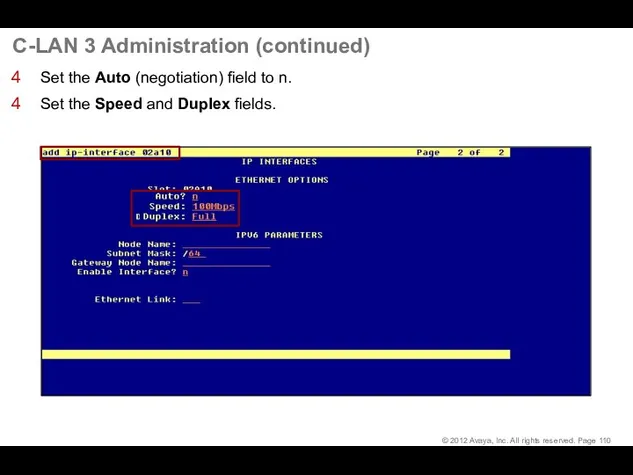
C-LAN 3 Administration (continued)
Set the Auto (negotiation) field to n.
Set the
C-LAN 3 Administration (continued)
Set the Auto (negotiation) field to n.
Set the
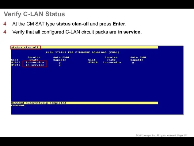
Verify C-LAN Status
At the CM SAT type status clan-all and press
Verify C-LAN Status
At the CM SAT type status clan-all and press
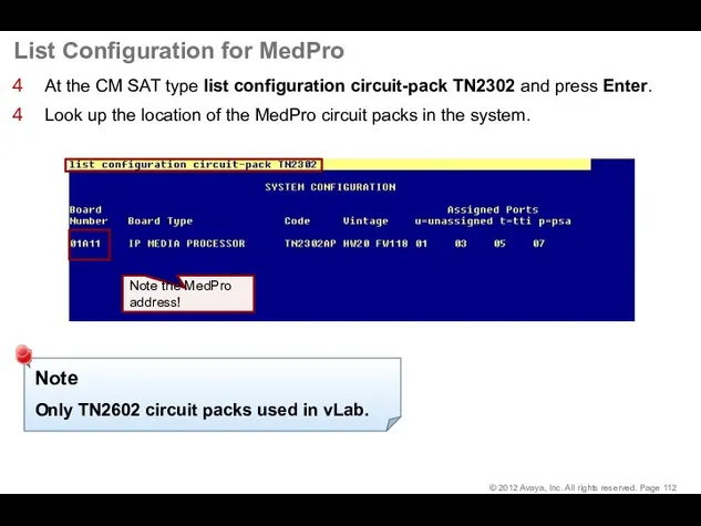
List Configuration for MedPro
At the CM SAT type list configuration circuit-pack
List Configuration for MedPro
At the CM SAT type list configuration circuit-pack
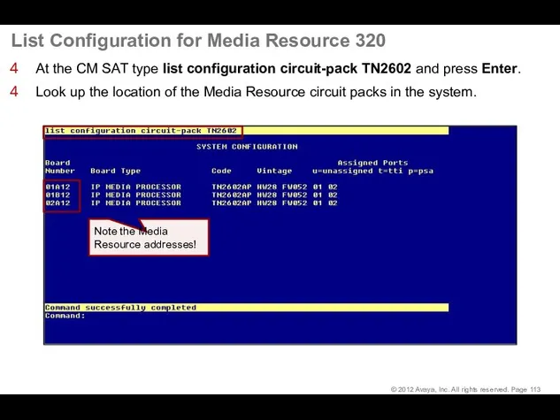
List Configuration for Media Resource 320
At the CM SAT type list
List Configuration for Media Resource 320
At the CM SAT type list
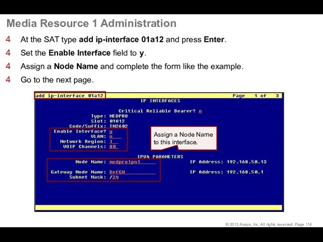
Media Resource 1 Administration
At the SAT type add ip-interface 01a12 and
Media Resource 1 Administration
At the SAT type add ip-interface 01a12 and
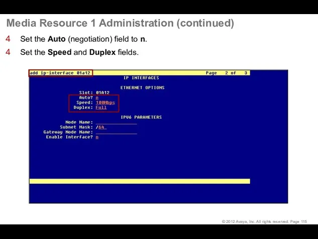
Media Resource 1 Administration (continued)
Set the Auto (negotiation) field to n.
Set
Media Resource 1 Administration (continued)
Set the Auto (negotiation) field to n.
Set
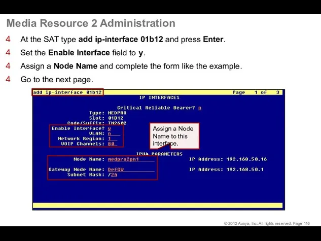
Media Resource 2 Administration
At the SAT type add ip-interface 01b12 and
Media Resource 2 Administration
At the SAT type add ip-interface 01b12 and
Media Resource 2 Administration (continued)
Set the Auto (negotiation) field to n.
Set
Media Resource 2 Administration (continued)
Set the Auto (negotiation) field to n.
Set
Media Resource 3 Administration
At the SAT type add ip-interface 02a12 and
Media Resource 3 Administration
At the SAT type add ip-interface 02a12 and
Media Resource 3 Administration (continued)
Set the Auto (negotiation) field to n.
Set
Media Resource 3 Administration (continued)
Set the Auto (negotiation) field to n.
Set
Verify Media Processor/Resource Status
At the SAT type status media-processor all and
Verify Media Processor/Resource Status
At the SAT type status media-processor all and
Make a Test Call
Make a Test Call
Administer CM Endpoints
Administer CM Endpoints
Administer CM Endpoints—Dial Plan
The dial plan interprets dialed digits.
Administer CM Endpoints—Dial Plan
The dial plan interprets dialed digits.
Administer CM Endpoints—Dial Plan (continued)
The recommended dial plan for this course
Administer CM Endpoints—Dial Plan (continued)
The recommended dial plan for this course
Administer CM Endpoints—Dial Plan (continued)
Type change dialplan analysis to administer the
Administer CM Endpoints—Dial Plan (continued)
Type change dialplan analysis to administer the
Administer CM Endpoints—Create Endpoints
Launch Avaya Site Administration, select Advanced > Terminal
Administer CM Endpoints—Create Endpoints
Launch Avaya Site Administration, select Advanced > Terminal
Administer CM Endpoints—Create Endpoints (continued)
Repeat the administration for extension 1002.
At the
Administer CM Endpoints—Create Endpoints (continued)
Repeat the administration for extension 1002.
At the
Administer CM Endpoints—Create Endpoints (continued)
Confirm the station administration:
At the SAT command
Administer CM Endpoints—Create Endpoints (continued)
Confirm the station administration:
At the SAT command
Administer one-X® Communicator
Administer one-X® Communicator
Administer one-X® Communicator
Click Start and select Programs > Avaya one-X® Communicator
Administer one-X® Communicator
Click Start and select Programs > Avaya one-X® Communicator
Administer one-X® Communicator (continued)
Configure the settings as follows:
Using – select H.323
Administer one-X® Communicator (continued)
Configure the settings as follows:
Using – select H.323
Administer one-X® Communicator (continued)
Log on with the extension (station number) and
Administer one-X® Communicator (continued)
Log on with the extension (station number) and
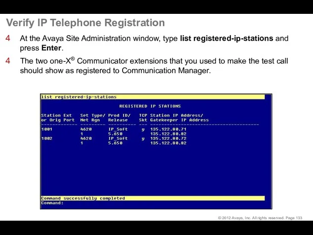
Verify IP Telephone Registration
At the Avaya Site Administration window, type
Verify IP Telephone Registration
At the Avaya Site Administration window, type
Dial the Test Call
Dial the Test Call
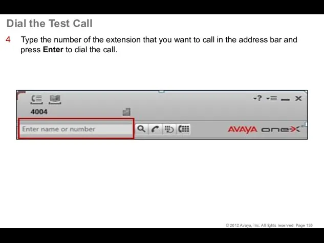
Dial the Test Call
Type the number of the extension that you
Dial the Test Call
Type the number of the extension that you
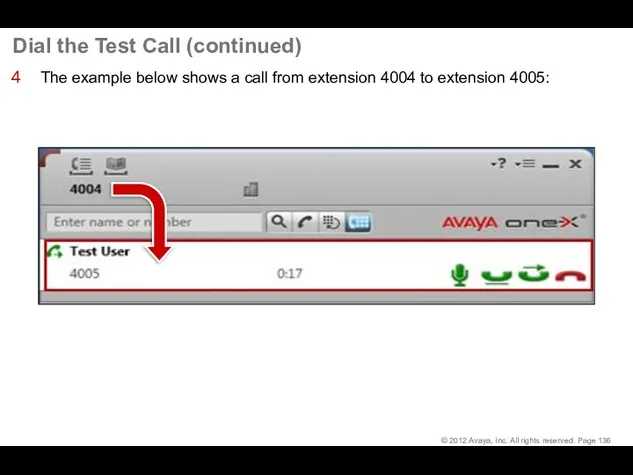
Dial the Test Call (continued)
The example below shows a call from
Dial the Test Call (continued)
The example below shows a call from
Dial the Test Call (continued)
The Call Log at the bottom of
Dial the Test Call (continued)
The Call Log at the bottom of
 Доповнення власної карти мітками
 Путь дерева (3 кл)
 Понятие модели: модели натурные и информационные. Назначение и свойства моделей
 Операции с каталогами
 Основные правила Web-дизайна
 Расчёт стоимости обслуживания и модернизации компьютерной сети в ООО НПФ Пакер
 Алгоритмдеу және программалау
 Антивирус Касперского
 Электронная почта. Сетевое коллективное взаимодействие. Сетевой этикет
 BIM: Междисциплинарная координация
 CNBetterLife Compensation plan
 Управляющие структуры (PHP, лекция 3)
 Frontend Comments Extended 9
 Збереження зображень. Діалогові вікна, їх об’єкти. Інформаційні вікна (урок 17, 5 клас)
 Технология создания презентаций с помощью сервиса Prezi.com
 Программирование на языке Python. Символьные строки
 Работа с графикой в документах Microsoft Office Word 2007
 Спільна діяльність у мережі інтернет
 Программирование на языке Паскаль. Массивы
 Безопасность информационных систем. Обеспечение безопасности компьютерных сетей
 Межпроцессное взаимодействие. Синхронизация потоков с использованием объектов ядра Windows 2000+
 ТЗ 2. Доработка цепочки документов. Выгрузка справочников из старой 1С 8 в новую 1С сервисный центр
 Ввод данных в SPSS
 Облачные технологии
 Понятие имитационное моделирование
 База данных - основа информационной системы
 СУБД. Объекты баз данных
 Программирование на языке Python. § 54. Алгоритм и его свойства