- Mesh Creation According to Predicted y+

Содержание
- 2. Introduction This short tutorial demonstrates in practice the technique for Creating the desired wall spacing in
- 3. Part A: Predicting and calculating the desired wall spacing Taken from lecture 7 in ANSYS Fluent
- 4. Part B: Creating the desired wall spacing in ANSYS Mesh Unarchive the supplied yPlus_example.wbpz. The geometry
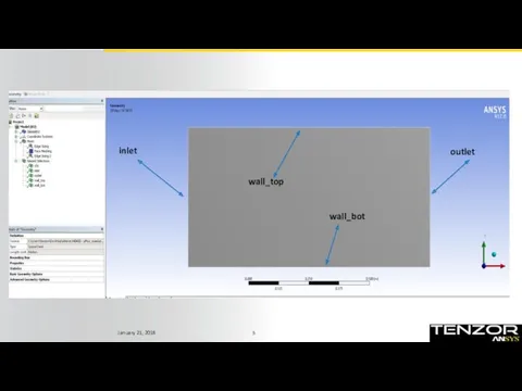
- 5. wall_top wall_bot inlet outlet
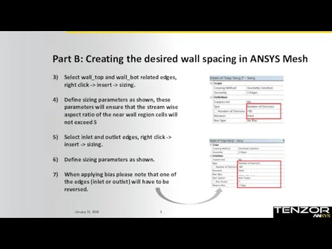
- 6. Part B: Creating the desired wall spacing in ANSYS Mesh Select wall_top and wall_bot related edges,
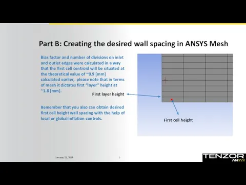
- 7. Part B: Creating the desired wall spacing in ANSYS Mesh Bias factor and number of divisions
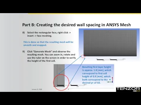
- 8. Part B: Creating the desired wall spacing in ANSYS Mesh Select the rectangular face, right click
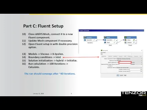
- 9. Part C: Fluent Setup Close ANSYS Mesh, connect it to a new Fluent component. Update Mesh
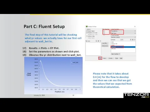
- 10. Part C: Fluent Setup The final step of this tutorial will be checking what y+ values
- 12. Скачать презентацию
Introduction
This short tutorial demonstrates in practice the technique for Creating the
Introduction
This short tutorial demonstrates in practice the technique for Creating the
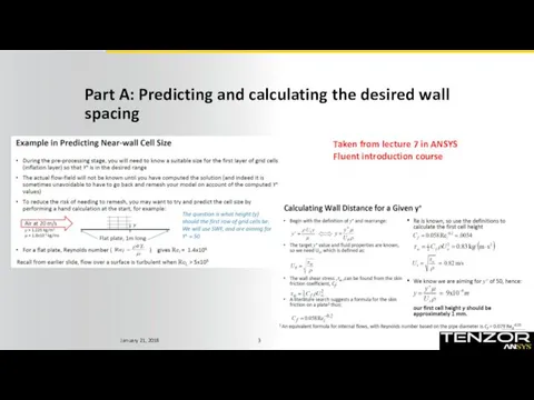
Part A: Predicting and calculating the desired wall spacing
Taken from lecture
Part A: Predicting and calculating the desired wall spacing
Taken from lecture
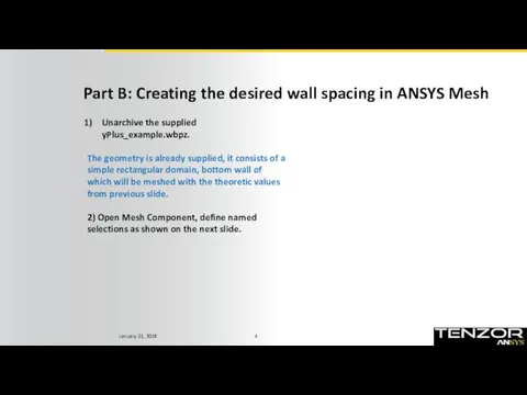
Part B: Creating the desired wall spacing in ANSYS Mesh
Unarchive the
Part B: Creating the desired wall spacing in ANSYS Mesh
Unarchive the
wall_top
wall_bot
inlet
outlet
wall_top
wall_bot
inlet
outlet
Part B: Creating the desired wall spacing in ANSYS Mesh
Select wall_top
Part B: Creating the desired wall spacing in ANSYS Mesh
Select wall_top
Part B: Creating the desired wall spacing in ANSYS Mesh
Bias factor
Part B: Creating the desired wall spacing in ANSYS Mesh
Bias factor
Part B: Creating the desired wall spacing in ANSYS Mesh
Select the
Part B: Creating the desired wall spacing in ANSYS Mesh
Select the
Part C: Fluent Setup
Close ANSYS Mesh, connect it to a new
Part C: Fluent Setup
Close ANSYS Mesh, connect it to a new
Part C: Fluent Setup
The final step of this tutorial will be
Part C: Fluent Setup
The final step of this tutorial will be
 ГИС Панорама. Разработка программного обеспечения и архитектура геоинформационных систем
 Система автоматизации Умный дом. Разработка подсистемы Панель администратора
 Электрондық үкімет порталының жалпы түрі
 Введение в теорию информации и кодирования. (Лекция 1)
 Правила составления библиографического списка
 Интеграция с ФГИС Меркурий в программах от фирмы 1С
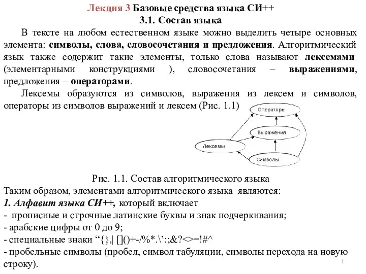 Базовые средства языка СИ++. Лекция 3
 Кодирование звуковой информации
 Презентация Структура данных
 Coding schemes, data representation
 Програмне забезпечення для комп'ютерної поліграфії
 Разработка игры в стиле Backroom
 Методология моделирования. Системный анализ
 Quick Start Guide. How to prepare CV
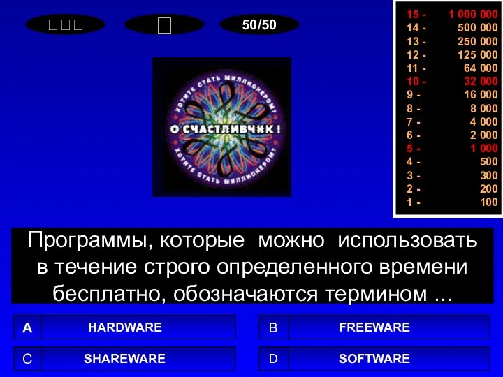 Хотите стать миллионером?
 Программно-аппаратные комплексы ViPNet IDS
 Системы счисления
 Списки и таблицы в HTML
 Web design. Перехід від Web 1.0 до Web 2.0
 Безпека в інтернеті
 загрузка торрента
 Дистанционный урок
 Аналитические операции в ГИС (геоинформационные системы)
 Создание видеоурока по информатике
 Электронная информационно-образовательная среда (ЭИОС). Сибирский институт управления
 Элементы алгебры логики (Упрощение логических выражений)
 Условный оператор
 Организация данных. Данные, информация, информационные системы