- Minimum Equipment List (MEL)

Содержание
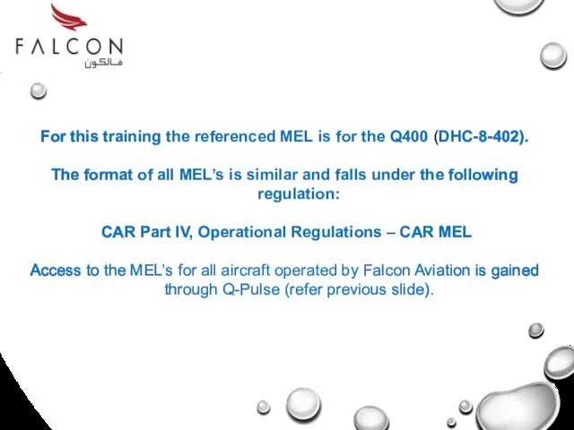
- 3. For this training the referenced MEL is for the Q400 (DHC-8-402). The format of all MEL’s
- 4. At the completion of this training you will be able to: Navigate your way through the
- 5. Part 1: MEL Origin & Philosophy. Part 2: MEL Structure Part 3: Process & Techlog Entry
- 6. MEL Origin & Philosophy Part 1
- 7. Master Minimum Equipment List A Master Minimum Equipment List (MMEL) is an approved document created specifically
- 8. End of Part 1
- 9. Minimum Equipment List (MEL) MEL Structure Part 2
- 10. All modern Airworthiness Authorities require that a MEL be carried in the aircraft when flown Therefore
- 11. This is an example of the GCAA approval letter of the DHC-8-402 MEL Structure
- 12. List of Effective pages: This part of the document will indicate what amendments have occurred. The
- 13. Table of contents: This part of the document will indicate how the MEL is structured as
- 14. Table of contents (cont’d): MEL Structure
- 15. Preamble: - is an introductory statement for the correct usage and application of the part 1
- 16. Definitions: - Also listed in the preamble will be a list of common definitions used throughout
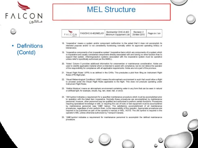
- 17. Definitions MEL Structure
- 18. Definitions (Contd) MEL Structure
- 19. All aircraft have their MEL’s designed around a standardized format but the content can be very
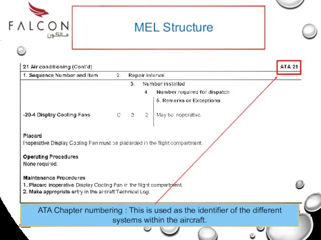
- 20. MEL Structure ATA Chapter numbering : This is used as the identifier of the different systems
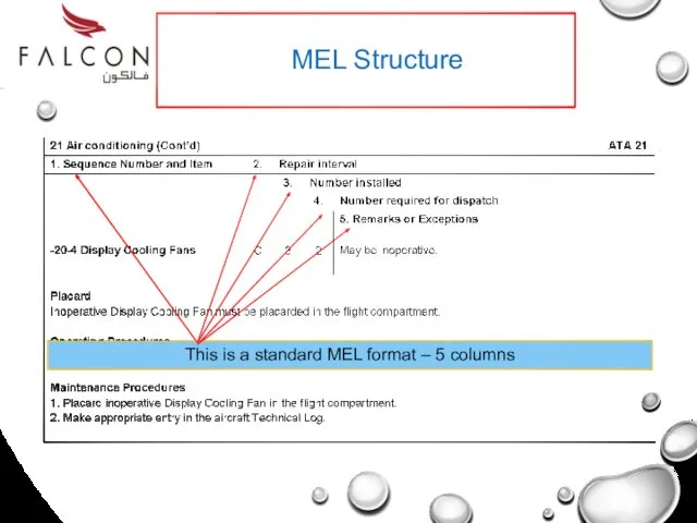
- 21. MEL Structure This is a standard MEL format – 5 columns
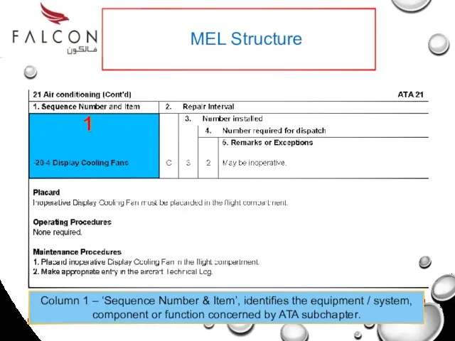
- 22. MEL Structure Column 1 – ‘Sequence Number & Item’, identifies the equipment / system, component or
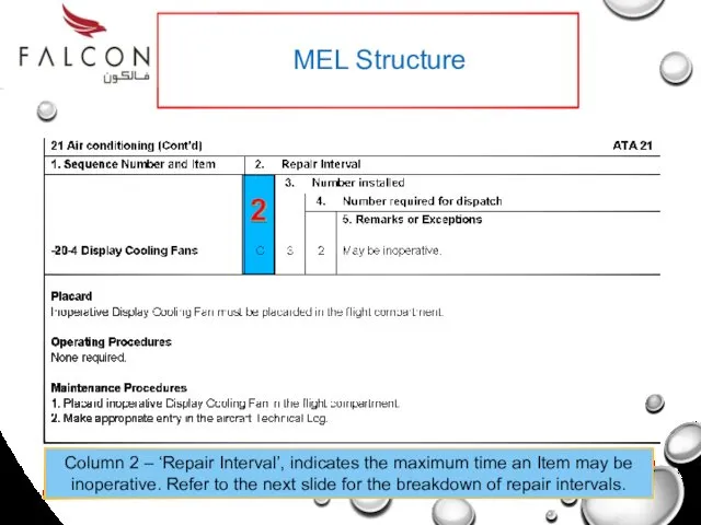
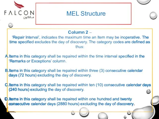
- 23. MEL Structure Column 2 – ‘Repair Interval’, indicates the maximum time an Item may be inoperative.
- 24. MEL Structure Column 2 – ‘Repair Interval’, indicates the maximum time an Item may be inoperative.
- 25. MEL Structure MEL Repair Interval Extension Programme Purpose Under certain conditions, such as a shortage of
- 26. MEL Repair Interval Extension Request
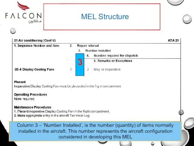
- 27. MEL Structure Column 3 – ‘Number Installed’, is the number (quantity) of items normally installed in
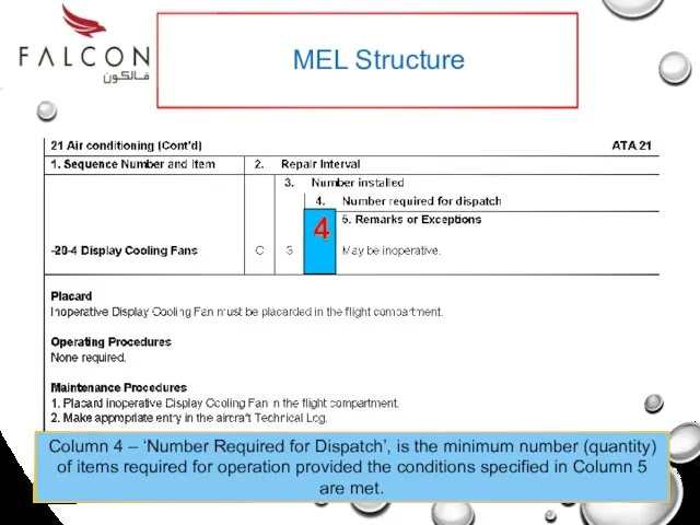
- 28. MEL Structure Column 4 – ‘Number Required for Dispatch’, is the minimum number (quantity) of items
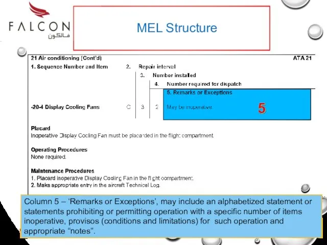
- 29. MEL Structure Column 5 – ‘Remarks or Exceptions’, may include an alphabetized statement or statements prohibiting
- 30. End of Part 2
- 31. PROCESS & TECH LOG ENTRY Part 3 AN EXAMPLE OF HOW TO USE THE MEL
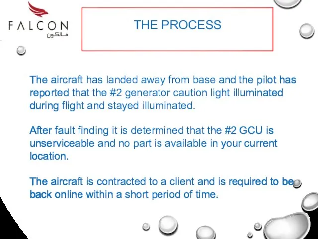
- 32. THE PROCESS The aircraft has landed away from base and the pilot has reported that the
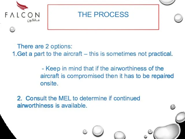
- 33. THE PROCESS There are 2 options: Get a part to the aircraft – this is sometimes
- 34. THE PROCESS 1st – we will look at the MEL. 2nd – we will finalise the
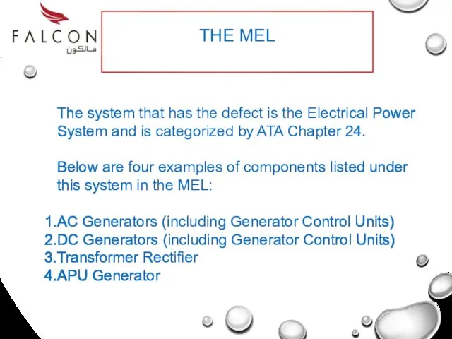
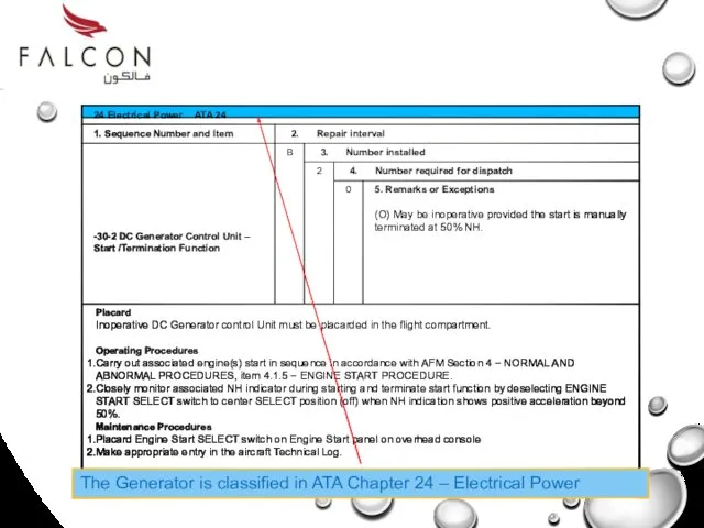
- 35. THE MEL The system that has the defect is the Electrical Power System and is categorized
- 36. The Generator is classified in ATA Chapter 24 – Electrical Power
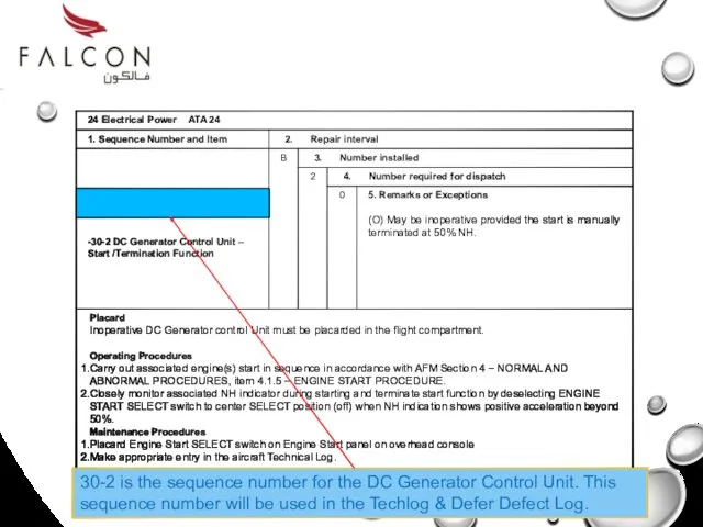
- 37. 30-2 is the sequence number for the DC Generator Control Unit. This sequence number will be
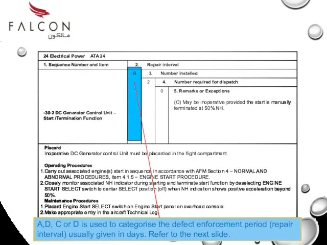
- 38. A,D, C or D is used to categorise the defect enforcement period (repair interval) usually given
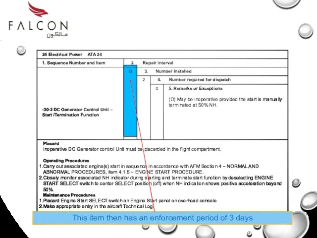
- 39. This item then has an enforcement period of 3 days
- 40. This indicates that there are 2 DC Generator Control Units fitted to the aircraft.
- 41. This indicates that the aircraft can be airworthy with inoperable DC Generator Control Units as long
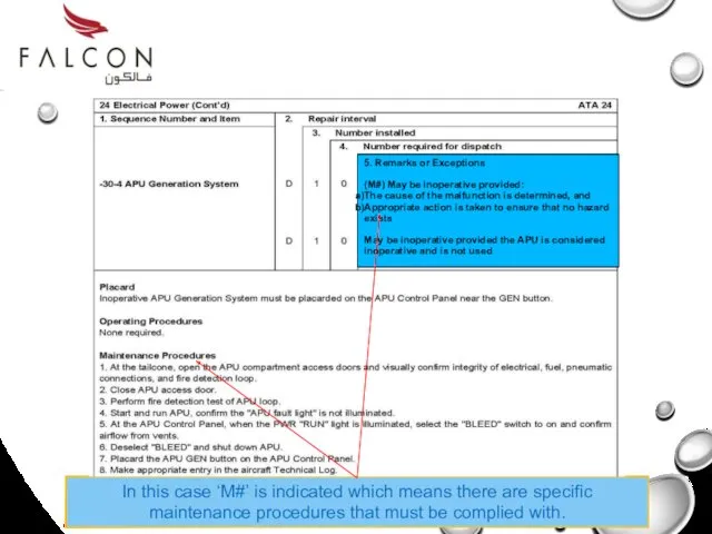
- 42. This could be either ‘O’ or ‘M’. In this case O is indicated which means there
- 43. This could be either ‘O’ or ‘M’. In this case O is indicated which means there
- 44. The following symbols could also be in Column 5: (M) – Indicates that a maintenance task
- 45. 5. Remarks or Exceptions (M#) May be inoperative provided: The cause of the malfunction is determined,
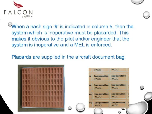
- 46. When a hash sign ‘#’ is indicated in column 5, then the system which is inoperative
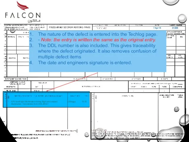
- 47. The Techlog Entry
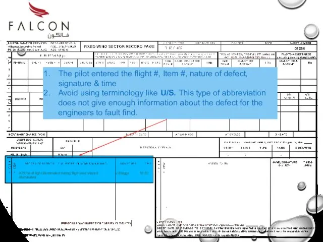
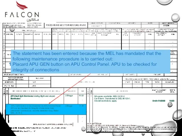
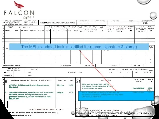
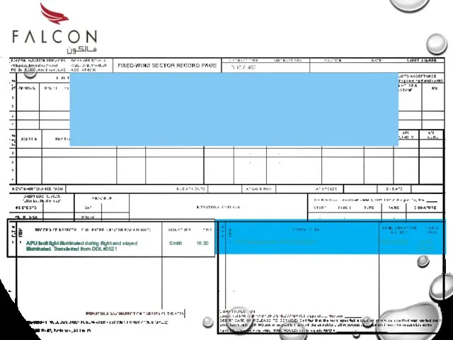
- 48. APU fault light illuminated during flight and stayed illuminated J.Bloggs 16:30 The pilot entered the flight
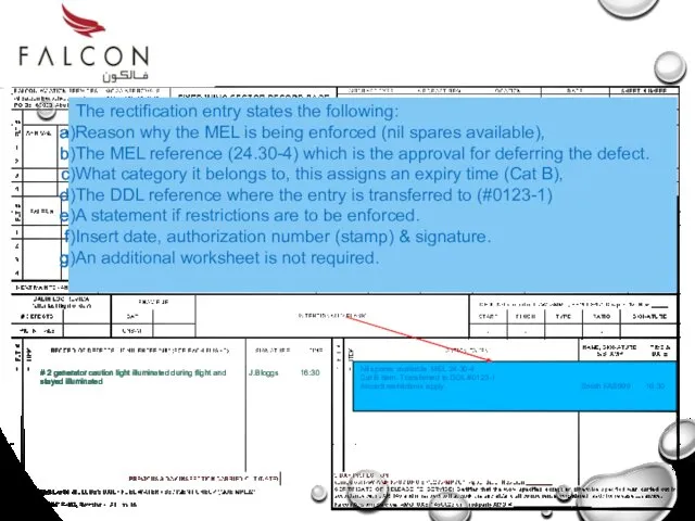
- 49. Nil spares available. MEL 24.30-4 Cat B item. Transferred to DDL #0123-1. Aircraft restrictions apply. Smith
- 50. Nil spares available. MEL 24.30.4 Cat B item. Transferred to DDL #0123-1. Aircraft restrictions apply. Smith
- 51. Nil spares available. MEL 24.XX.X. Cat B item. Transferred to DDL #0123-1. Aircraft restrictions apply. Smith
- 52. 1 This number is assigned to a new entry and follows the sequence from the previous
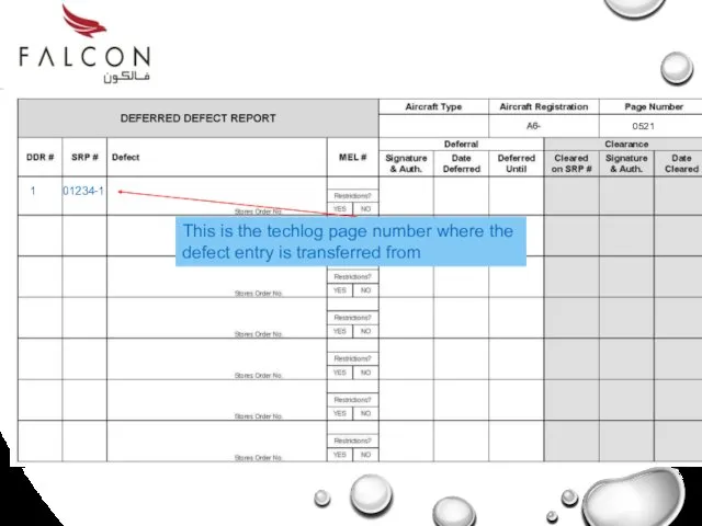
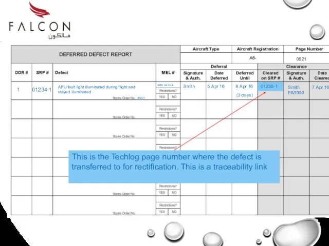
- 53. 1 01234-1 This is the techlog page number where the defect entry is transferred from 0521
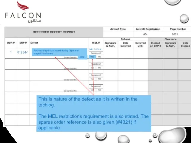
- 54. 1 01234-1 This is nature of the defect as it is written in the techlog. The
- 55. 1 01234-1 The engineers or pilots signature & stamp (as applicable is entered) and the date
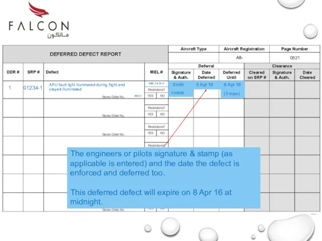
- 56. Release to Service When the Techlog and deferred defect log entries are completed the aircraft is
- 57. End of Part 3
- 58. Defect Repair Part 4
- 59. Defect Repair When the spare part has arrived or when the deferment date has expired, the
- 60. Techlog Entries The part has been replaced and the documentation now has to be completed. This
- 61. 1 01234-1 This is the Techlog page number where the defect is transferred to for rectification.
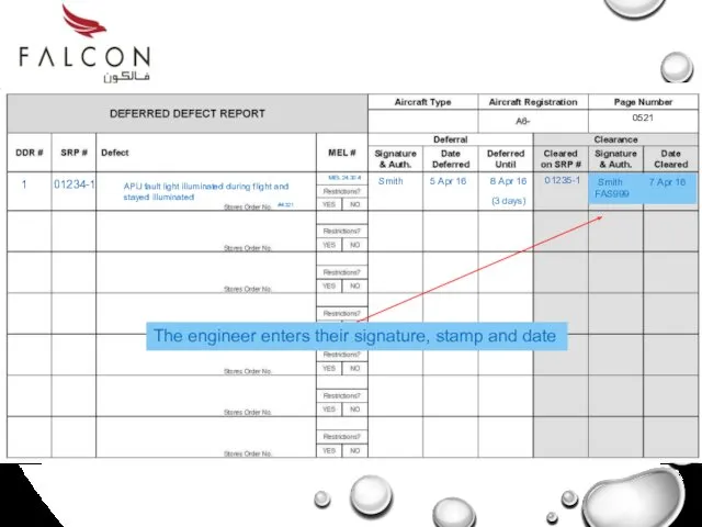
- 62. 1 01234-1 The engineer enters their signature, stamp and date APU fault light illuminated during flight
- 63. APU fault light illuminated during flight and stayed illuminated. Transferred from DDL #0521 J.Bloggs 16:30 The
- 64. APU Replaced Ref: AMM 000000001 Smith FAS999 20:30 7 Apr 16 APU fault light illuminated during
- 68. Point cursor on screen & double click to start.
- 69. End of Part 5
- 71. Скачать презентацию
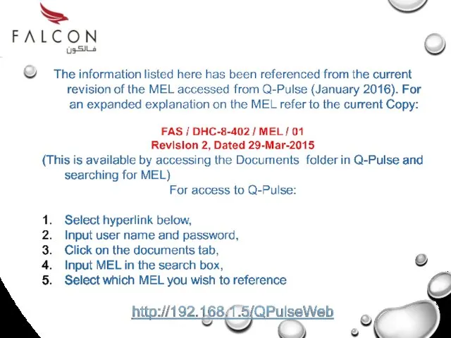
For this training the referenced MEL is for the Q400 (DHC-8-402).
For this training the referenced MEL is for the Q400 (DHC-8-402).
At the completion of this training you will be able to:
Navigate
Navigate
Part 1: MEL Origin & Philosophy.
Part 2: MEL Structure
Part
Part 2: MEL Structure
Part
MEL Origin & Philosophy
Part 1
Part 1
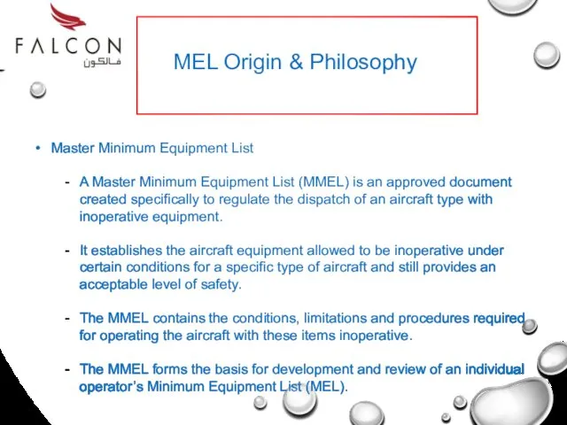
Master Minimum Equipment List
A Master Minimum Equipment List (MMEL) is an
Master Minimum Equipment List
A Master Minimum Equipment List (MMEL) is an
End of Part 1
End of Part 1
Minimum Equipment List
(MEL)
MEL Structure
Part 2
Minimum Equipment List
(MEL)
MEL Structure
Part 2
All modern Airworthiness Authorities require that a MEL be carried in
All modern Airworthiness Authorities require that a MEL be carried in
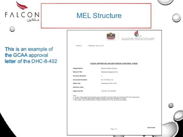
This is an example of the GCAA approval letter of the
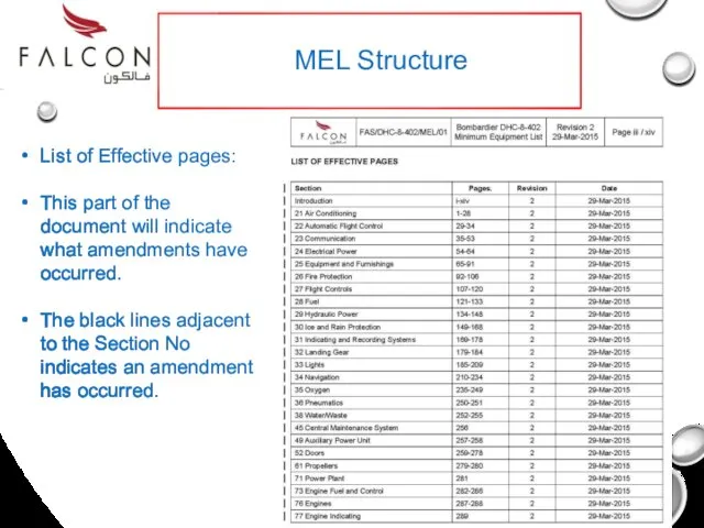
List of Effective pages:
This part of the document will indicate what
List of Effective pages:
This part of the document will indicate what
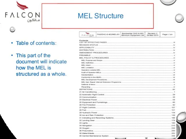
Table of contents:
This part of the document will indicate how the
Table of contents:
This part of the document will indicate how the
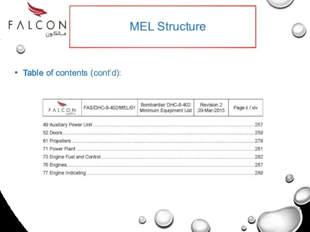
Table of contents (cont’d):
MEL Structure
Table of contents (cont’d):
MEL Structure
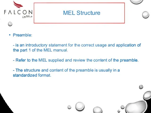
Preamble:
- is an introductory statement for the correct usage and
Preamble:
- is an introductory statement for the correct usage and
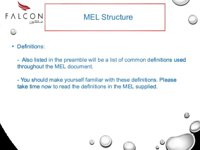
Definitions:
- Also listed in the preamble will be a list
Definitions:
- Also listed in the preamble will be a list
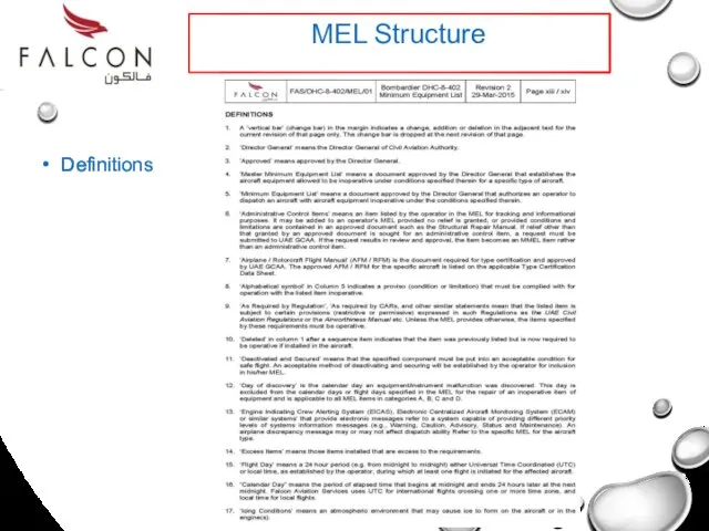
Definitions
MEL Structure
Definitions
MEL Structure
Definitions
(Contd)
MEL Structure
Definitions
(Contd)
MEL Structure
All aircraft have their MEL’s designed around a standardized format but
All aircraft have their MEL’s designed around a standardized format but
MEL Structure
ATA Chapter numbering : This is used as the identifier
MEL Structure
ATA Chapter numbering : This is used as the identifier
MEL Structure
This is a standard MEL format – 5 columns
MEL Structure
This is a standard MEL format – 5 columns
MEL Structure
Column 1 – ‘Sequence Number & Item’, identifies the equipment
MEL Structure
Column 1 – ‘Sequence Number & Item’, identifies the equipment
MEL Structure
Column 2 – ‘Repair Interval’, indicates the maximum time an
MEL Structure
Column 2 – ‘Repair Interval’, indicates the maximum time an
MEL Structure
Column 2 –
‘Repair Interval’, indicates the maximum time an
MEL Structure
Column 2 –
‘Repair Interval’, indicates the maximum time an
MEL Structure
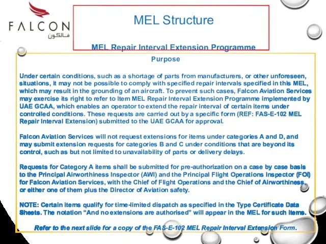
MEL Repair Interval Extension Programme
Purpose
Under certain conditions, such as a
MEL Structure
MEL Repair Interval Extension Programme
Purpose
Under certain conditions, such as a
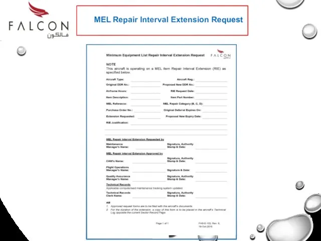
MEL Repair Interval Extension Request
MEL Repair Interval Extension Request
MEL Structure
Column 3 – ‘Number Installed’, is the number (quantity) of
MEL Structure
Column 3 – ‘Number Installed’, is the number (quantity) of
MEL Structure
Column 4 – ‘Number Required for Dispatch’, is the minimum
MEL Structure
Column 4 – ‘Number Required for Dispatch’, is the minimum
MEL Structure
Column 5 – ‘Remarks or Exceptions’, may include an alphabetized
MEL Structure
Column 5 – ‘Remarks or Exceptions’, may include an alphabetized

End of Part 2
End of Part 2
PROCESS &
TECH LOG ENTRY
Part 3
AN EXAMPLE OF HOW TO USE
TECH LOG ENTRY
Part 3
AN EXAMPLE OF HOW TO USE
THE PROCESS
The aircraft has landed away from base and the pilot
The aircraft has landed away from base and the pilot
THE PROCESS
There are 2 options:
Get a part to the aircraft –
There are 2 options:
Get a part to the aircraft –

THE PROCESS
1st – we will look at the MEL.
2nd – we
1st – we will look at the MEL.
2nd – we
THE MEL
The system that has the defect is the Electrical Power
The system that has the defect is the Electrical Power
The Generator is classified in ATA Chapter 24 – Electrical Power
The Generator is classified in ATA Chapter 24 – Electrical Power
30-2 is the sequence number for the DC Generator Control Unit.
30-2 is the sequence number for the DC Generator Control Unit.
A,D, C or D is used to categorise the defect enforcement
A,D, C or D is used to categorise the defect enforcement
This item then has an enforcement period of 3 days
This item then has an enforcement period of 3 days
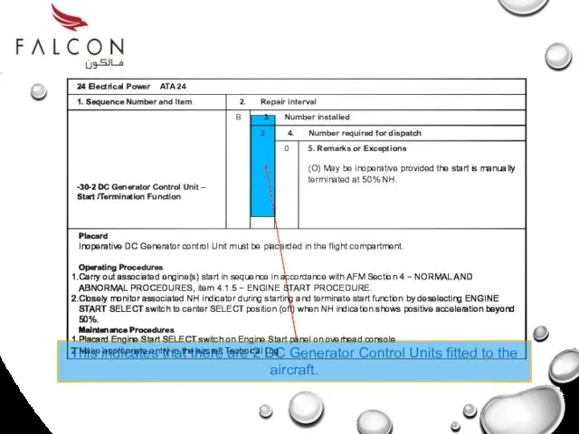
This indicates that there are 2 DC Generator Control Units fitted
This indicates that there are 2 DC Generator Control Units fitted
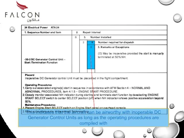
This indicates that the aircraft can be airworthy with inoperable DC
This indicates that the aircraft can be airworthy with inoperable DC

This could be either ‘O’ or ‘M’. In this case O
This could be either ‘O’ or ‘M’. In this case O
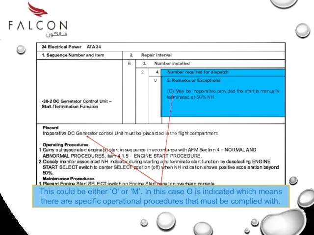
This could be either ‘O’ or ‘M’. In this case O
This could be either ‘O’ or ‘M’. In this case O
The following symbols could also be in Column 5:
(M) – Indicates
The following symbols could also be in Column 5:
(M) – Indicates
5. Remarks or Exceptions
(M#) May be inoperative provided:
The cause of the
5. Remarks or Exceptions
(M#) May be inoperative provided:
The cause of the
When a hash sign ‘#’ is indicated in column 5, then
When a hash sign ‘#’ is indicated in column 5, then

The Techlog Entry
The Techlog Entry
APU fault light illuminated during flight and stayed illuminated
J.Bloggs 16:30
The
APU fault light illuminated during flight and stayed illuminated
J.Bloggs 16:30
The
Nil spares available. MEL 24.30-4
Cat B item. Transferred to DDL #0123-1.
Aircraft
Nil spares available. MEL 24.30-4
Cat B item. Transferred to DDL #0123-1.
Aircraft
Nil spares available. MEL 24.30.4
Cat B item. Transferred to DDL #0123-1.
Aircraft
Nil spares available. MEL 24.30.4
Cat B item. Transferred to DDL #0123-1.
Aircraft
Nil spares available. MEL 24.XX.X.
Cat B item. Transferred to DDL #0123-1.
Aircraft
Nil spares available. MEL 24.XX.X.
Cat B item. Transferred to DDL #0123-1.
Aircraft
1
This number is assigned to a new entry and follows the
1
This number is assigned to a new entry and follows the
1 01234-1
This is the techlog page number where the defect entry
1 01234-1
This is the techlog page number where the defect entry
1 01234-1
This is nature of the defect as it is written
1 01234-1
This is nature of the defect as it is written
1 01234-1
The engineers or pilots signature & stamp (as applicable is
1 01234-1
The engineers or pilots signature & stamp (as applicable is
Release to Service
When the Techlog and deferred defect log entries are
Release to Service
When the Techlog and deferred defect log entries are

End of Part 3
End of Part 3
Defect Repair
Part 4
Defect Repair
Part 4
Defect Repair
When the spare part has arrived or when the deferment
Defect Repair
When the spare part has arrived or when the deferment
Techlog Entries
The part has been replaced and the documentation now has
Techlog Entries
The part has been replaced and the documentation now has
1 01234-1
This is the Techlog page number where the defect is
1 01234-1
This is the Techlog page number where the defect is
1 01234-1
The engineer enters their signature, stamp and date
APU fault light
1 01234-1
The engineer enters their signature, stamp and date
APU fault light
APU fault light illuminated during flight and stayed illuminated. Transferred from
APU fault light illuminated during flight and stayed illuminated. Transferred from
APU Replaced Ref: AMM 000000001 Smith FAS999 20:30
7 Apr
APU Replaced Ref: AMM 000000001 Smith FAS999 20:30
7 Apr


Point cursor on screen & double click to start.
Point cursor on screen & double click to start.
End of Part 5
End of Part 5
 Керування правами доступу
 Информационные технологии в образовании
 Информатизация общества. Характеристики информатизации в России
 Что представляет собой термин мультимедиа технология?
 Компьютерная графика. Растровые и векторные графические редакторы
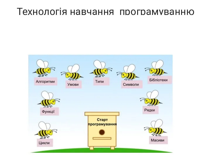 Технологія навчання програмуванню
 Онлайн-кассы
 Основные принципы применения языка LAD. Таймеры и счетчики (на примере пакета CoDeSys)
 Введение. Основные понятия машинного обучения. Применение машинного обучения в искусственном интеллекте
 Опыт внедрения электронного учебника в библиотеке
 Презентация ФАЙЛЫ И ФАЙЛОВАЯ СИСТЕМА, часть 1 и 2.
 Типы алгоритмов(Разветвляющиеся)
 Информационный процесс обмена данными
 Шифрование информации
 Развитие компьютерной техники
 Парадигмы программирования
 Поведенческие паттерны
 Базы данных (БД). СУБД
 Кіріспе. Java тілі туралы түсінік
 Friar SlidesCarnival
 История возникновения и развития информационных технологий
 Удостоверяющий центр ООО Инфолайн: Электронная отчётность
 Программирование на языке MATLAB. Программирование алгоритмов линейной структуры
 Сети и системы телекоммуникаций. Протоколы маршрутизации
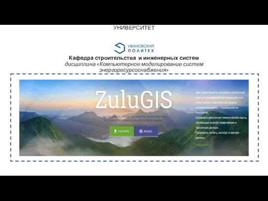 Геоинформационная система ZuluGIS
 Рекурсивные функции
 Школьный портал ЕОИС
 Жаңа ақпараттық оқыту технологиясы