- Network. Fundamentals

Содержание
- 2. AGENDA 1 Internet Protocol
- 3. General Terms
- 4. Providing Resources in a Network Networks of Many Sizes Small Home / Office Networks Medium to
- 5. Network Components End Devices Either the source or destination of a message Name some end devices
- 6. Network Components Network Representations What do the symbols represent? Topology Diagrams Physical Logical
- 7. LANs and WANs Local Area Networks Spans across small geographical area Interconnects end devices Administrated by
- 8. The Internet, Intranets, and Extranets The Internet Worldwide collection of interconnected networks Not owned by any
- 9. Converged Networks Traditional Separate Networks Each network with its own rules and The Converging Network Capable
- 10. Reliable Network Four Basic Characteristics of Network Architecture Fault Tolerance Scalability Quality of Service (QoS) Security
- 11. Network Topology
- 12. Topologies Controlling Access to the Media Physical and Logical Topologies
- 13. WAN Topologies Common Physical WAN Topologies Point-to-point Hub and spoke Mesh Physical Point-to-Point Topology Logical Point-to-Point
- 14. LAN Topologies Physical LAN Topologies Half and Full Duplex Media Access Control Methods Contention-Based Access CSMA/CD
- 15. Network Protocols
- 16. The Rules Rule Establishment Identified sender and receiver Common language and grammar Speed and timing of
- 17. Protocols Rules that Govern Communications Network Protocols The role of protocols How the message is formatted
- 18. Protocol Suites Protocol Suites and Industry Standards TCP/IP is an open standard Can you name other
- 19. OSI Model
- 20. Reference Models The Benefits of Using a Layered Model Name some benefits The OSI Reference Model
- 21. Data Encapsulation Message Segmentation Segmentation - Break communication into pieces Multiplexing – interleaving the pieces Protocol
- 22. Data Access Network Addresses Source IP address Destination IP address Deliver the IP packet from the
- 23. Network Media
- 24. Copper Cabling Characteristics of Copper Cabling Inexpensive, easy to install, low resistance to electric current Distance
- 25. UTP Cabling Properties of UTP Cabling Cancellation of EMI and RFI signals with twisted pairs UTP
- 26. Fiber-Optic Cabling Properties of Fiber-Optic Cabling Transmits data over longer distances Flexible, but thin strands of
- 27. Wireless Media Properties of Wireless Media Data communications using radio or microwave frequencies Types of Wireless
- 28. Wireless Media
- 29. Ethernet
- 30. Ethernet MAC Addresses MAC Addresses and Hexadecimal MAC address is 48-bit long and expressed as 12
- 31. Ethernet MAC Addresses Unicast MAC Address Unique address used when a frame is sent from a
- 32. The MAC Address Table Switch Fundamentals An Ethernet Switch is a Layer 2 device. It uses
- 33. Switch Forwarding Methods Frame Forwarding Methods on Cisco Switches Store-And-Forward Cut-Through Cut-Through Switching Fast-forward switching Lowest
- 34. Switch Port Settings Duplex and Speed Settings Full-duplex – Both ends of the connection can send
- 35. MAC and IP The combination of MAC and IP facilitate the End-to-End communication Layer 2 addresses
- 36. ARP Introduction to ARP ARP allows the source to request the MAC address of the destination
- 37. Command Line Utilities arp - is a utility for managing ARP table Parameters: /? - help
- 38. ARP Issues ARP Broadcasts ARP requests can flood the local segment ARP Spoofing Attackers can respond
- 39. Internet Protocol
- 40. Network Layer in Communications The Network Layer End to End Transport processes Addressing end devices Encapsulation
- 41. Characteristics of the IP Protocol Encapsulating IP Segments are encapsulated into IP packets for transmission The
- 42. IPv4 Packet Version = 0100 DS = Packet Priority TTL = Limits life of Packet Protocol
- 43. IPv6 Packet Limitations of IPv4 IP address depletion Internet routing table expansion Lack of end-to-end connectivity
- 45. Скачать презентацию
AGENDA
1
Internet Protocol
AGENDA
1
Internet Protocol

General Terms
General Terms
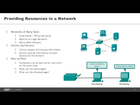
Providing Resources in a Network
Networks of Many Sizes
Small Home / Office
Providing Resources in a Network
Networks of Many Sizes
Small Home / Office
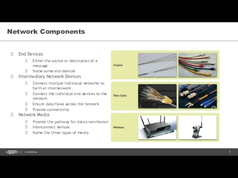
Network Components
End Devices
Either the source or destination of a message
Name some
Network Components
End Devices
Either the source or destination of a message
Name some
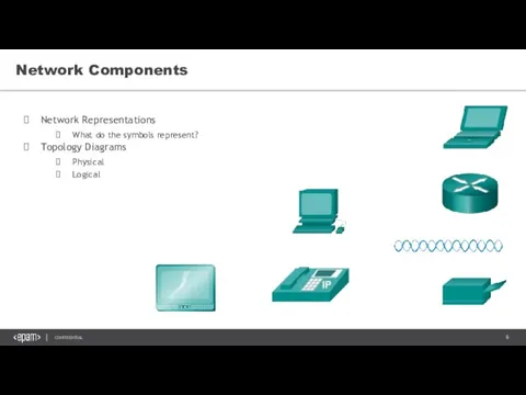
Network Components
Network Representations
What do the symbols represent?
Topology Diagrams
Physical
Logical
Network Components
Network Representations
What do the symbols represent?
Topology Diagrams
Physical
Logical
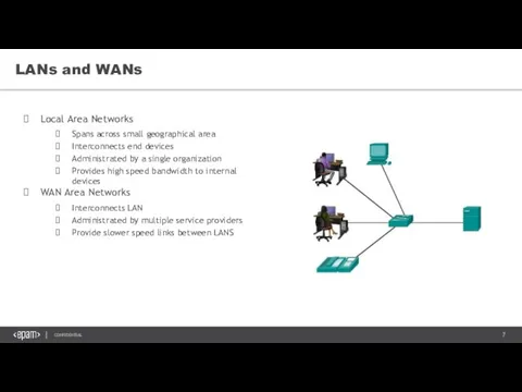
LANs and WANs
Local Area Networks
Spans across small geographical area
Interconnects end devices
Administrated
LANs and WANs
Local Area Networks
Spans across small geographical area
Interconnects end devices
Administrated
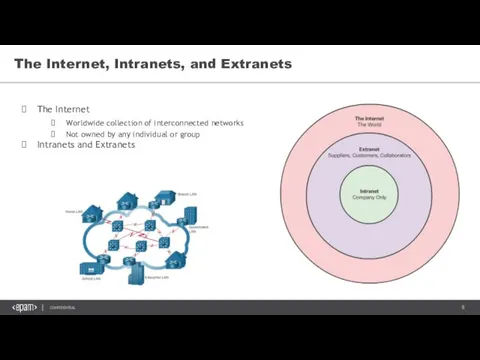
The Internet, Intranets, and Extranets
The Internet
Worldwide collection of interconnected networks
Not owned
The Internet, Intranets, and Extranets
The Internet
Worldwide collection of interconnected networks
Not owned
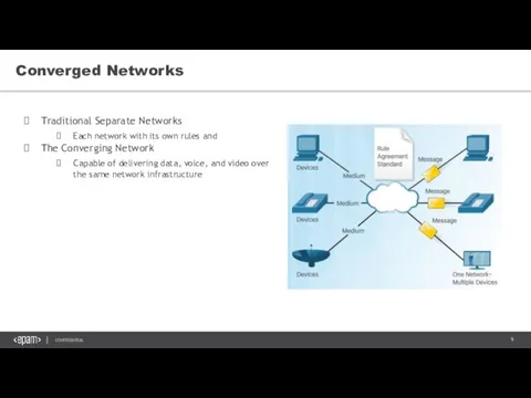
Converged Networks
Traditional Separate Networks
Each network with its own rules and
The
Converged Networks
Traditional Separate Networks
Each network with its own rules and
The
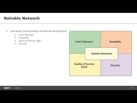
Reliable Network
Four Basic Characteristics of Network Architecture
Fault Tolerance
Scalability
Quality of Service (QoS)
Security
Reliable Network
Four Basic Characteristics of Network Architecture
Fault Tolerance
Scalability
Quality of Service (QoS)
Security
Network Topology
Network Topology
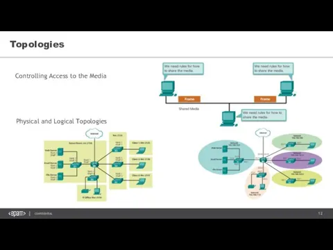
Topologies
Controlling Access to the Media
Physical and Logical Topologies
Topologies
Controlling Access to the Media
Physical and Logical Topologies
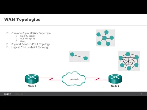
WAN Topologies
Common Physical WAN Topologies
Point-to-point
Hub and spoke
Mesh
Physical Point-to-Point Topology
Logical Point-to-Point Topology
WAN Topologies
Common Physical WAN Topologies
Point-to-point
Hub and spoke
Mesh
Physical Point-to-Point Topology
Logical Point-to-Point Topology
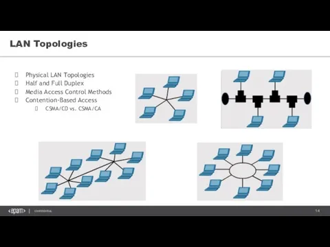
LAN Topologies
Physical LAN Topologies
Half and Full Duplex
Media Access Control Methods
Contention-Based Access
CSMA/CD
LAN Topologies
Physical LAN Topologies
Half and Full Duplex
Media Access Control Methods
Contention-Based Access
CSMA/CD
Network Protocols
Network Protocols
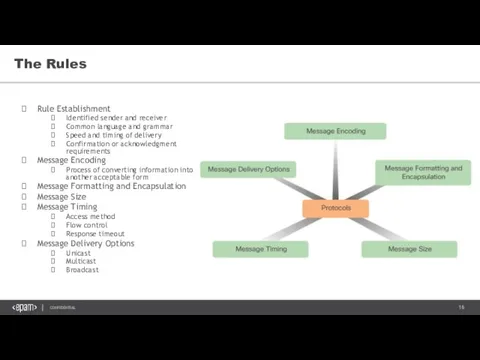
The Rules
Rule Establishment
Identified sender and receiver
Common language and grammar
Speed and timing
The Rules
Rule Establishment
Identified sender and receiver
Common language and grammar
Speed and timing
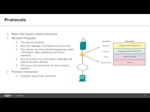
Protocols
Rules that Govern Communications
Network Protocols
The role of protocols
How the message is
Protocols
Rules that Govern Communications
Network Protocols
The role of protocols
How the message is
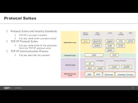
Protocol Suites
Protocol Suites and Industry Standards
TCP/IP is an open standard
Can you
Protocol Suites
Protocol Suites and Industry Standards
TCP/IP is an open standard
Can you
OSI Model
OSI Model
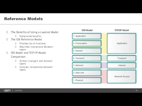
Reference Models
The Benefits of Using a Layered Model
Name some benefits
The OSI
Reference Models
The Benefits of Using a Layered Model
Name some benefits
The OSI
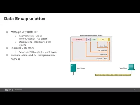
Data Encapsulation
Message Segmentation
Segmentation - Break communication into pieces
Multiplexing – interleaving the
Data Encapsulation
Message Segmentation
Segmentation - Break communication into pieces
Multiplexing – interleaving the
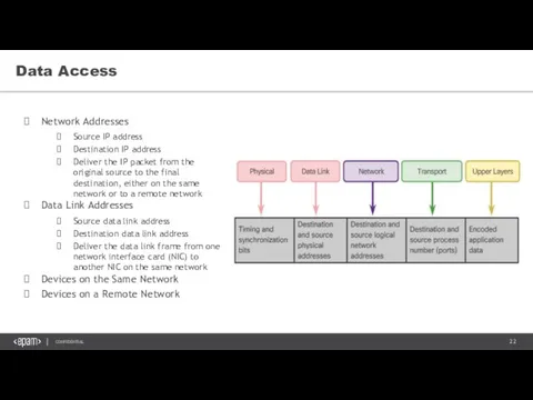
Data Access
Network Addresses
Source IP address
Destination IP address
Deliver the IP packet from
Data Access
Network Addresses
Source IP address
Destination IP address
Deliver the IP packet from
Network Media
Network Media
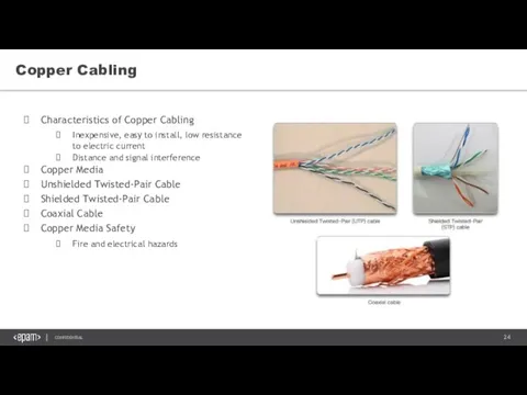
Copper Cabling
Characteristics of Copper Cabling
Inexpensive, easy to install, low resistance to
Copper Cabling
Characteristics of Copper Cabling
Inexpensive, easy to install, low resistance to
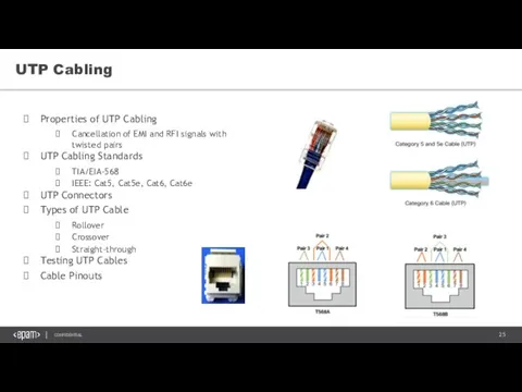
UTP Cabling
Properties of UTP Cabling
Cancellation of EMI and RFI signals with
UTP Cabling
Properties of UTP Cabling
Cancellation of EMI and RFI signals with
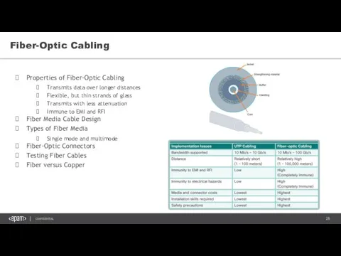
Fiber-Optic Cabling
Properties of Fiber-Optic Cabling
Transmits data over longer distances
Flexible, but thin
Fiber-Optic Cabling
Properties of Fiber-Optic Cabling
Transmits data over longer distances
Flexible, but thin
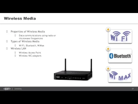
Wireless Media
Properties of Wireless Media
Data communications using radio or microwave frequencies
Types
Wireless Media
Properties of Wireless Media
Data communications using radio or microwave frequencies
Types
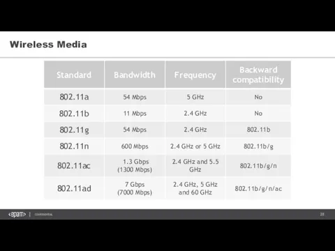
Wireless Media
Wireless Media
Ethernet
Ethernet
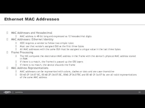
Ethernet MAC Addresses
MAC Addresses and Hexadecimal
MAC address is 48-bit long and
Ethernet MAC Addresses
MAC Addresses and Hexadecimal
MAC address is 48-bit long and
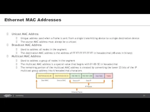
Ethernet MAC Addresses
Unicast MAC Address
Unique address used when a frame
Ethernet MAC Addresses
Unicast MAC Address
Unique address used when a frame
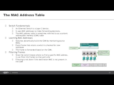
The MAC Address Table
Switch Fundamentals
An Ethernet Switch is a Layer 2
The MAC Address Table
Switch Fundamentals
An Ethernet Switch is a Layer 2
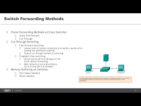
Switch Forwarding Methods
Frame Forwarding Methods on Cisco Switches
Store-And-Forward
Cut-Through
Cut-Through Switching
Fast-forward switching
Lowest level
Switch Forwarding Methods
Frame Forwarding Methods on Cisco Switches
Store-And-Forward
Cut-Through
Cut-Through Switching
Fast-forward switching
Lowest level
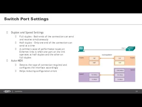
Switch Port Settings
Duplex and Speed Settings
Full-duplex – Both ends of the connection
Switch Port Settings
Duplex and Speed Settings
Full-duplex – Both ends of the connection
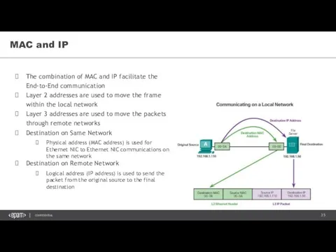
MAC and IP
The combination of MAC and IP facilitate the End-to-End
MAC and IP
The combination of MAC and IP facilitate the End-to-End
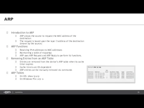
ARP
Introduction to ARP
ARP allows the source to request the MAC address
ARP
Introduction to ARP
ARP allows the source to request the MAC address
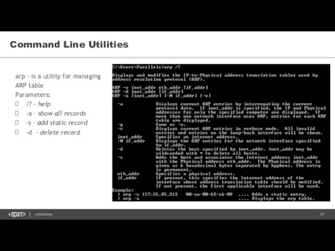
Command Line Utilities
arp - is a utility for managing ARP table
Parameters:
/?
Command Line Utilities
arp - is a utility for managing ARP table
Parameters:
/?
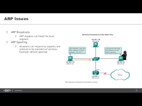
ARP Issues
ARP Broadcasts
ARP requests can flood the local segment
ARP Spoofing
Attackers can
ARP Issues
ARP Broadcasts
ARP requests can flood the local segment
ARP Spoofing
Attackers can
Internet Protocol
Internet Protocol
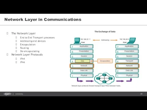
Network Layer in Communications
The Network Layer
End to End Transport processes
Addressing end
Network Layer in Communications
The Network Layer
End to End Transport processes
Addressing end
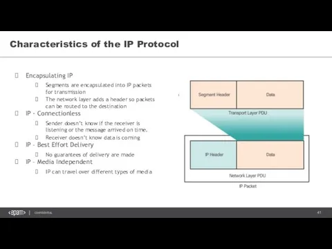
Characteristics of the IP Protocol
Encapsulating IP
Segments are encapsulated into IP packets
Characteristics of the IP Protocol
Encapsulating IP
Segments are encapsulated into IP packets
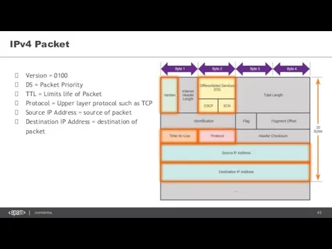
IPv4 Packet
Version = 0100
DS = Packet Priority
TTL = Limits life of
IPv4 Packet
Version = 0100
DS = Packet Priority
TTL = Limits life of
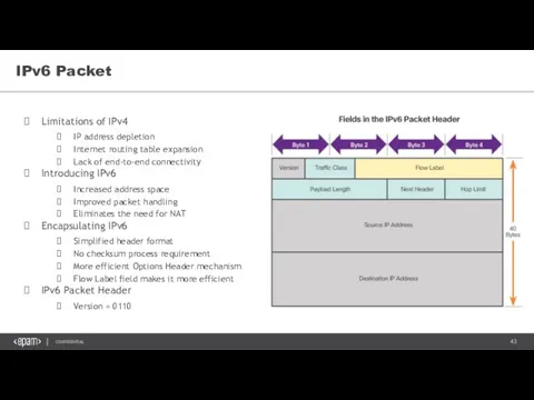
IPv6 Packet
Limitations of IPv4
IP address depletion
Internet routing table expansion
Lack of end-to-end
IPv6 Packet
Limitations of IPv4
IP address depletion
Internet routing table expansion
Lack of end-to-end
 Презентация Нормализация отношений баз данных
 Дизайн электронных и мультимедийных изданий
 Online retun. Back end system and ruling system Ver 01
 Microsoft Word 2010. Интерфейс
 QuickTime — технологія та серія застосунків, розроблених Apple для відтворення різних форматів
 Объектно-ориентированное программирование в Ruby
 Аналитический блок СБиС
 Ответы на вопросы на тему Интернет
 Установка и настройка FTP сервера на базе операционной системы Fedora
 Системное ПО (часть II)
 Advantages and Disadvantages of Internet
 Обработка информации Изменение формы представления информации. Преобразование по заданным правилам. 5 класс
 Тестовая документация. ПО для управления тестовой документацией. Лекция 4
 Теги и атрибуты оформления CSS
 Файлы и файловая система (8 класс)
 Пользовательский интерфейс
 Упорядочиваемое и восстанавливаемость. Назначение многопользовательских СУБД
 Заливка цветом. Другие операции
 Издательство Elsevier
 Building the user interface by using HTML5. Text, graphics and media
 Инженерная и компьютерная графика. Системы автоматизированного проектирования (САПР), тема 9
 Представление числовой информации в компьютере
 Разработка АРМ для сотрудников автосервиса
 Создание видеороликов в программе Movie Maker
 Web-дизайн
 Вредоносные программы. Методы профилактики и защиты
 Стандарты, методологии разработки ПО, описания БП используемые в работе
 Компьютерная мышь