QOS Requirements and Service Level Agreements. Application SLA Requirements. VoIP. Video Streaming презентация
- QOS Requirements and Service Level Agreements. Application SLA Requirements. VoIP. Video Streaming

Содержание
- 2. Application SLA Requirements Different applications have different SLA requirements; the impact that different network services with
- 3. Voice over IP Voice over IP (VoIP) is most commonly transported as a digitally encoded stream
- 4. Voice over IP Figure 3 VoIP end-systems components of delay
- 5. Voice over IP codec characteristics
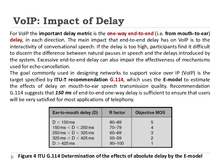
- 6. VoIP: Impact of Delay For VoIP the important delay metric is the one-way end-to-end (i.e. from
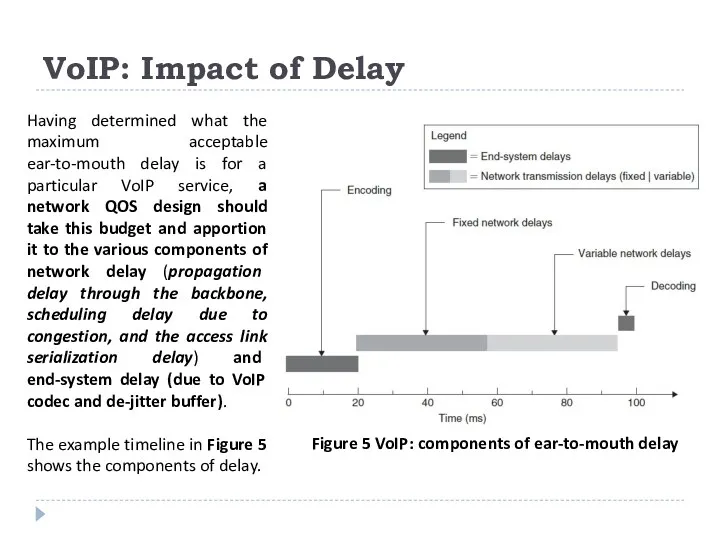
- 7. VoIP: Impact of Delay Having determined what the maximum acceptable ear-to-mouth delay is for a particular
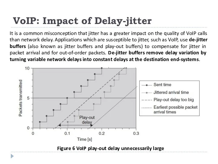
- 8. VoIP: Impact of Delay-jitter It is a common misconception that jitter has a greater impact on
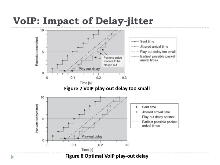
- 9. VoIP: Impact of Delay-jitter Figure 7 VoIP play-out delay too small Figure 8 Optimal VoIP play-out
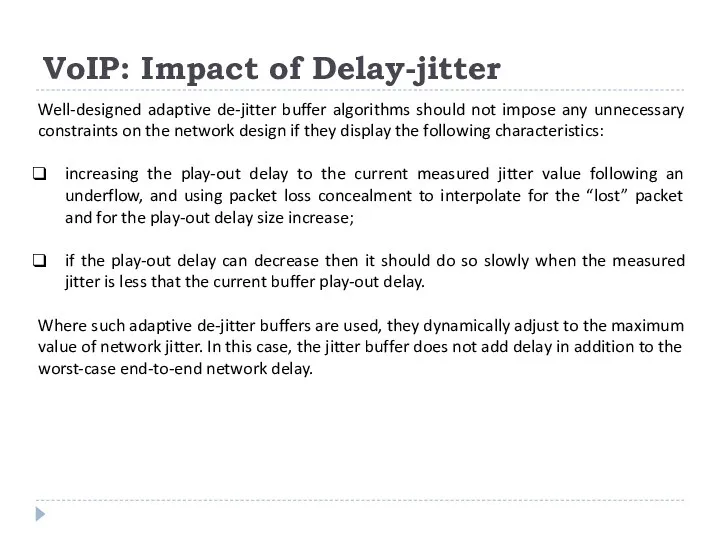
- 10. VoIP: Impact of Delay-jitter Well-designed adaptive de-jitter buffer algorithms should not impose any unnecessary constraints on
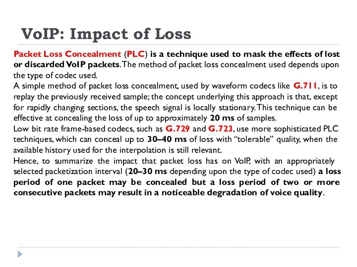
- 11. VoIP: Impact of Loss Packet Loss Concealment (PLC) is a technique used to mask the effects
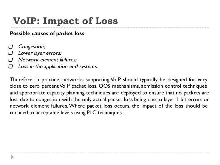
- 12. VoIP: Impact of Loss Possible causes of packet loss: Congestion; Lower layer errors; Network element failures;
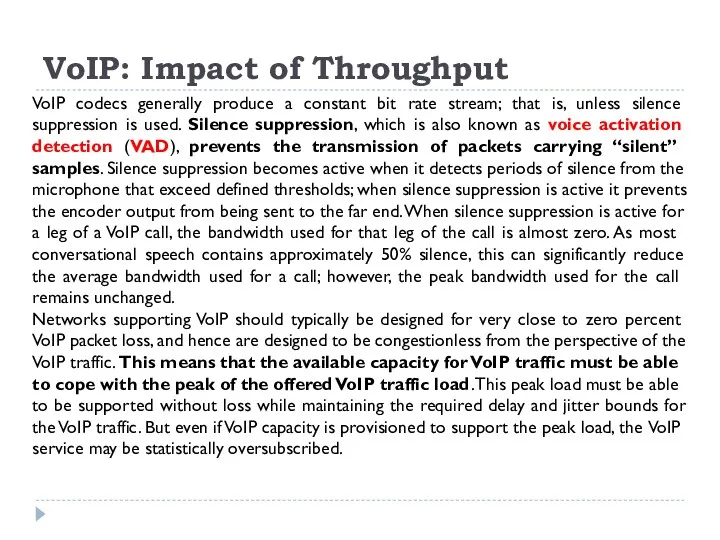
- 13. VoIP: Impact of Throughput VoIP codecs generally produce a constant bit rate stream; that is, unless
- 14. VoIP: Impact of Packet Re-ordering VoIP traffic is not commonly impacted by packet re-ordering, as the
- 15. Video. Video Streaming IP-based streaming video is most commonly transported as a data stream encoded using
- 16. Video Streaming An MPEG encoder converts and compresses a video signal into a series of pictures
- 17. Video Streaming Frames are arranged into a Group of Pictures or GOP. Unlike with VoIP where
- 18. Video Streaming: Impact of Delay For video streaming, the important delay metric is the one-way end-to-end
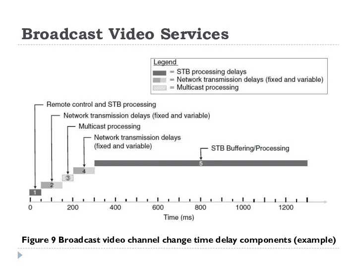
- 19. Broadcast Video Services Figure 9 Broadcast video channel change time delay components (example)
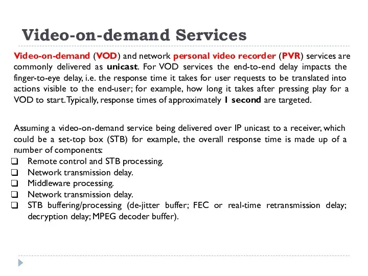
- 20. Video-on-demand Services Video-on-demand (VOD) and network personal video recorder (PVR) services are commonly delivered as unicast.
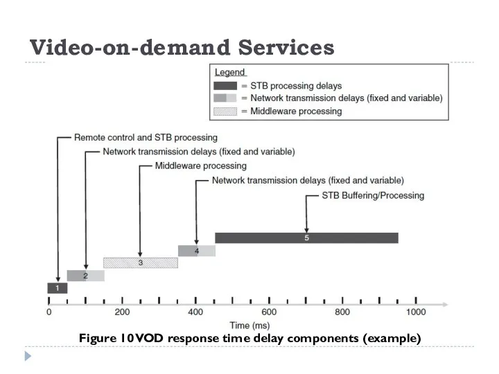
- 21. Video-on-demand Services Figure 10 VOD response time delay components (example)
- 22. Video Streaming Video Streaming: Impact of Delay-jitter Digital video decoders used in streaming video receivers need
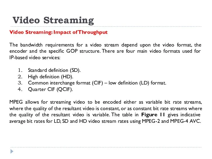
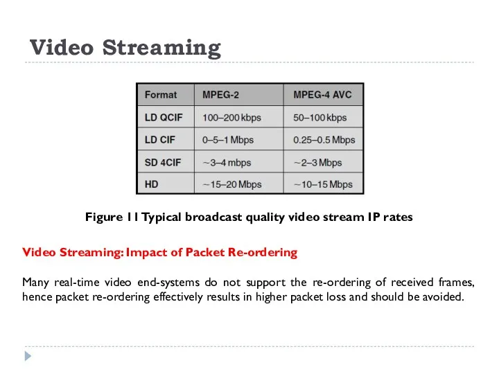
- 23. Video Streaming Video Streaming: Impact of Throughput The bandwidth requirements for a video stream depend upon
- 24. Video Streaming Video Streaming: Impact of Packet Re-ordering Many real-time video end-systems do not support the
- 25. Video Conferencing Video conferencing sessions are typically set up using the signaling protocols specified in ITU
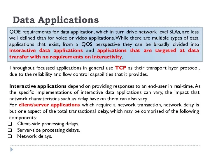
- 26. Data Applications QOE requirements for data application, which in turn drive network level SLAs, are less
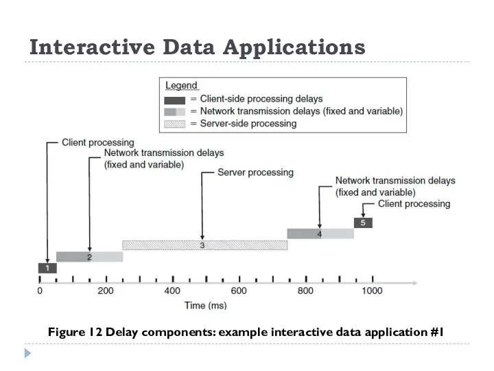
- 27. Interactive Data Applications Figure 12 Delay components: example interactive data application #1
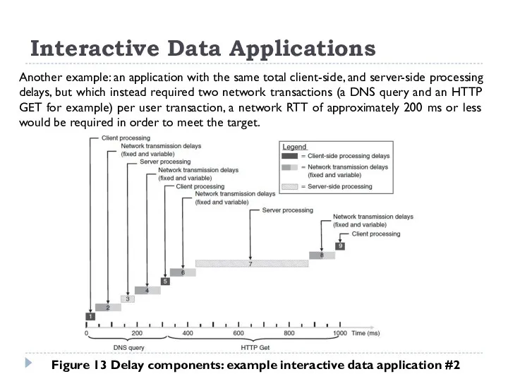
- 28. Interactive Data Applications Another example: an application with the same total client-side, and server-side processing delays,
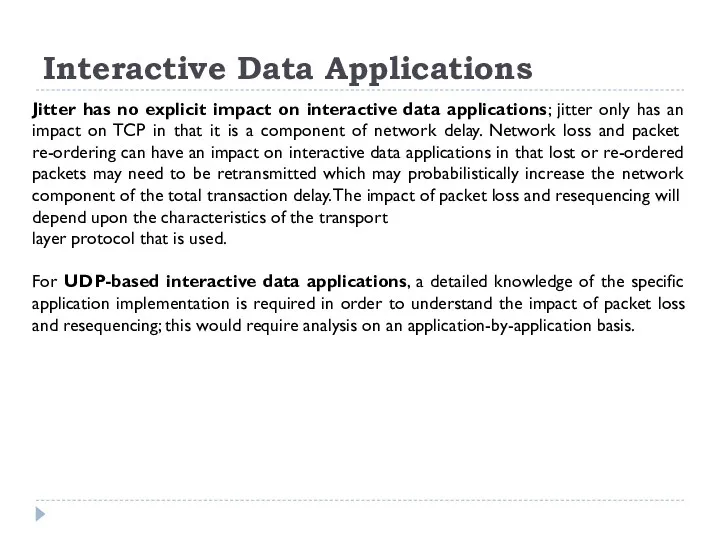
- 29. Interactive Data Applications Jitter has no explicit impact on interactive data applications; jitter only has an
- 30. On-line Gaming Multiplayer on-line or networked games are the most popular form of a type of
- 32. Скачать презентацию
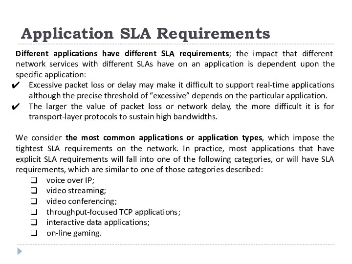
Application SLA Requirements
Different applications have different SLA requirements; the impact that
Application SLA Requirements
Different applications have different SLA requirements; the impact that
Voice over IP
Voice over IP (VoIP) is most commonly transported as
Voice over IP
Voice over IP (VoIP) is most commonly transported as
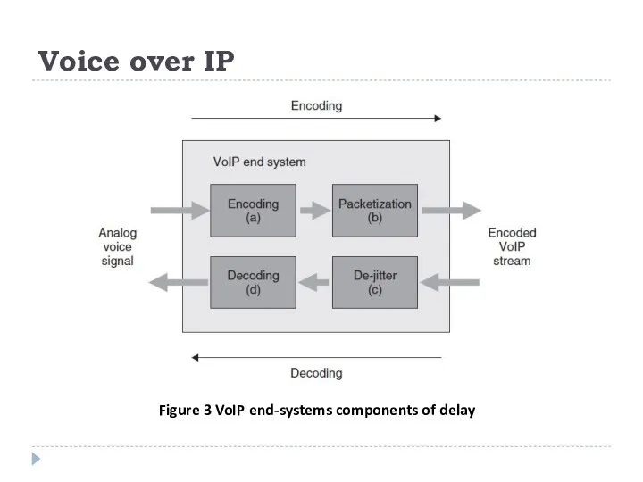
Voice over IP
Figure 3 VoIP end-systems components of delay
Voice over IP
Figure 3 VoIP end-systems components of delay
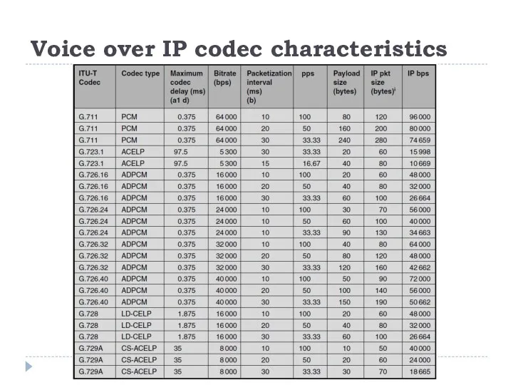
Voice over IP codec characteristics
Voice over IP codec characteristics
VoIP: Impact of Delay
For VoIP the important delay metric is the
VoIP: Impact of Delay
For VoIP the important delay metric is the
VoIP: Impact of Delay
Having determined what the maximum acceptable ear-to-mouth delay
VoIP: Impact of Delay
Having determined what the maximum acceptable ear-to-mouth delay
VoIP: Impact of Delay-jitter
It is a common misconception that jitter has
VoIP: Impact of Delay-jitter
It is a common misconception that jitter has
VoIP: Impact of Delay-jitter
Figure 7 VoIP play-out delay too small
Figure 8
VoIP: Impact of Delay-jitter
Figure 7 VoIP play-out delay too small
Figure 8
VoIP: Impact of Delay-jitter
Well-designed adaptive de-jitter buffer algorithms should not impose
VoIP: Impact of Delay-jitter
Well-designed adaptive de-jitter buffer algorithms should not impose
VoIP: Impact of Loss
Packet Loss Concealment (PLC) is a technique used
VoIP: Impact of Loss
Packet Loss Concealment (PLC) is a technique used
VoIP: Impact of Loss
Possible causes of packet loss:
Congestion;
Lower layer errors;
Network element
VoIP: Impact of Loss
Possible causes of packet loss:
Congestion;
Lower layer errors;
Network element
VoIP: Impact of Throughput
VoIP codecs generally produce a constant bit rate
VoIP: Impact of Throughput
VoIP codecs generally produce a constant bit rate
VoIP: Impact of Packet Re-ordering
VoIP traffic is not commonly impacted by
VoIP: Impact of Packet Re-ordering
VoIP traffic is not commonly impacted by
Video. Video Streaming
IP-based streaming video is most commonly transported as a
Video. Video Streaming
IP-based streaming video is most commonly transported as a
Video Streaming
An MPEG encoder converts and compresses a video signal into
Video Streaming
An MPEG encoder converts and compresses a video signal into
Video Streaming
Frames are arranged into a Group of Pictures or GOP.
Video Streaming
Frames are arranged into a Group of Pictures or GOP.

Video Streaming: Impact of Delay
For video streaming, the important delay metric
Video Streaming: Impact of Delay
For video streaming, the important delay metric
Broadcast Video Services
Figure 9 Broadcast video channel change time delay components
Broadcast Video Services
Figure 9 Broadcast video channel change time delay components
Video-on-demand Services
Video-on-demand (VOD) and network personal video recorder (PVR) services are
Video-on-demand Services
Video-on-demand (VOD) and network personal video recorder (PVR) services are
Video-on-demand Services
Figure 10 VOD response time delay components (example)
Video-on-demand Services
Figure 10 VOD response time delay components (example)
Video Streaming
Video Streaming: Impact of Delay-jitter
Digital video decoders used in streaming
Video Streaming
Video Streaming: Impact of Delay-jitter
Digital video decoders used in streaming
Video Streaming
Video Streaming: Impact of Throughput
The bandwidth requirements for a video
Video Streaming
Video Streaming: Impact of Throughput
The bandwidth requirements for a video
Video Streaming
Video Streaming: Impact of Packet Re-ordering
Many real-time video end-systems do
Video Streaming
Video Streaming: Impact of Packet Re-ordering
Many real-time video end-systems do
Video Conferencing
Video conferencing sessions are typically set up using the signaling
Video Conferencing
Video conferencing sessions are typically set up using the signaling
Data Applications
QOE requirements for data application, which in turn drive network
Data Applications
QOE requirements for data application, which in turn drive network
Interactive Data Applications
Figure 12 Delay components: example interactive data application #1
Interactive Data Applications
Figure 12 Delay components: example interactive data application #1
Interactive Data Applications
Another example: an application with the same total client-side,
Interactive Data Applications
Another example: an application with the same total client-side,
Interactive Data Applications
Jitter has no explicit impact on interactive data applications;
Interactive Data Applications
Jitter has no explicit impact on interactive data applications;

On-line Gaming
Multiplayer on-line or networked games are the most popular form
On-line Gaming
Multiplayer on-line or networked games are the most popular form
 Передача информации в древние времена и сегодня
 Презентация Утилиты. Текстовый редактор
 Способы шифрования
 Java input output-library
 C++ тілінде бағдарламалау
 Условный оператор
 Кружок по искусственному интеллекту. Семинар 2
 АИС Стационар. Система автоматизации деятельности медицинских учреждений
 Создание блога
 Концепция электронного правительства
 Цвет. Цветовое зрение. Измерение восприятия цвета. Диаграмма цветности. ColorFPM
 Електронне урядування та електронна демократія України
 Таргетированная реклама ВКонтакте
 Детективное агентство
 Aspects of internal corporate information security policies
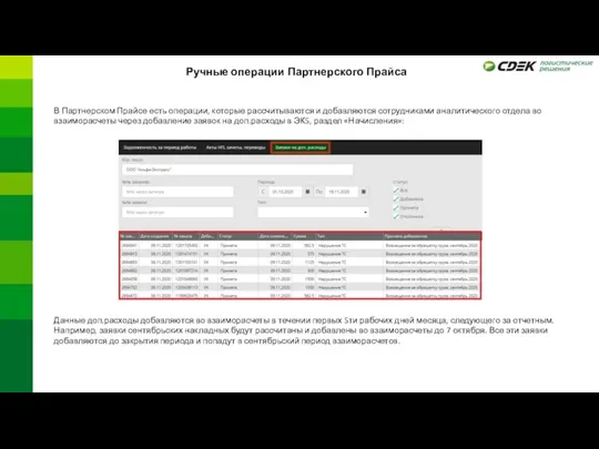 Ручные операции Партнерского Прайса
 CiGe Update firmware Using the tutorial
 Презентация к уроку в 9 классе Управление и кибернетика
 Формування державної політики у сфері кібербезпеки, реалізація Стратегії кібербезпеки України
 Практическая работа Служу России
 Поколение - z - школа блогеров
 Технология информационно-справочной работы с документами
 Рациональность в инди разработке
 Классификация ИТ
 Основы разработки сайтов
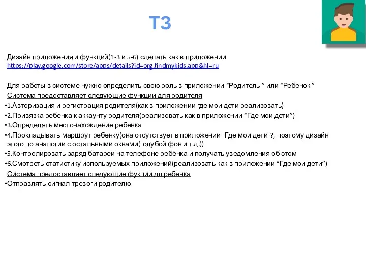 Дизайн приложения и функций. Приложения “Родитель ” или “Ребенок ”
 Історія виникнення ПК
 Пакеты и модули в Python