- Remy MF1/P1. Objectives

Содержание
- 2. Objectives After completing this training you should be able to: Install the Remy-MF1/P1 in the field.
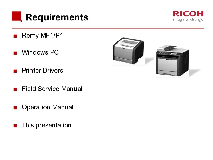
- 3. Requirements Remy MF1/P1 Windows PC Printer Drivers Field Service Manual Operation Manual This presentation
- 4. Pre-requisites and exam Before starting this training you must already have followed the My-Ricoh training for:
- 5. Module overview Introduction Maintenance Detailed Section Descriptions Troubleshooting
- 6. 1. Introduction
- 7. Remy models Remy-MF1a M156: SP 311SFN Remy-MF1aw M157: SP 311SFNw Remy-P1a M154: SP 311DN Remy-P1aw M155:
- 8. Differences from previous models
- 9. Differences from previous models
- 10. Other Points Remy-MF1/P1 do not have a USB host or the scan to USB feature. There
- 11. AIO Cartridges There are 3 types of AIO cartridges: Starter AIO: 1k per cartridge Low yield
- 12. Targets Monthly Print Volume Average: 0.7K Maximum: 5.8K Estimated Unit Life: 5 years or 200K prints
- 13. 2. Maintenance
- 14. PM Intervals There are no PM parts. There are three "yield parts", but given the ACV
- 15. Yield Parts Yield parts are rated to last for 120 K, which should be longer than
- 16. Access to Service Functions For MF models: To access Maintenance Mode, do the following: Type the
- 17. Image Adjustment This adjustment can be done by both service engineers and users. Service engineers: Maintenance
- 18. Firmware Updating You need a PC to do the firmware update. See the service manual for
- 19. 3. Detailed Section Descriptions
- 20. 3.1 Machine Overview
- 21. Component Layout – Remy-P1 Laser unit Quenching lamp Cartridge (AIO-type) Development roller Registration roller By-pass feed
- 22. Paper Path – Remy-P1 [A]: Duplex section [B]: Paper tray
- 23. Drive Layout – Remy-P1 Duplex motor Main motor Registration clutch Relay clutch Paper feed clutch
- 24. 3.2 Cover Removal & Part Replacement
- 25. General Precautions Before you start to work on the machine: If there are printer jobs in
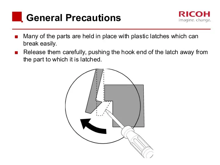
- 26. General Precautions Many of the parts are held in place with plastic latches which can break
- 27. Removing Covers The covers have a lot of hooks and tabs. Disconnect these carefully, as explained
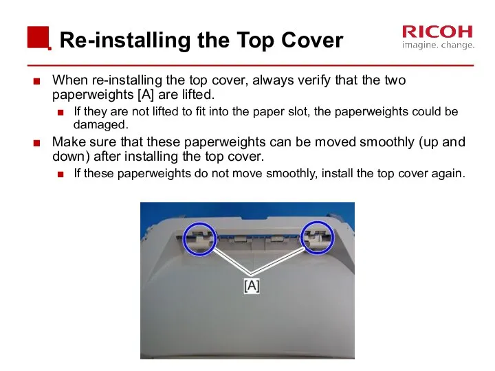
- 28. Re-installing the Top Cover When re-installing the top cover, always verify that the two paperweights [A]
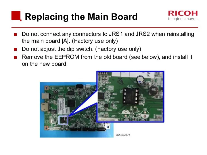
- 29. Replacing the Main Board Do not connect any connectors to JRS1 and JRS2 when reinstalling the
- 30. Install a New EEPROM Do the following settings after installing a new EEPROM. Input the PnP
- 31. 3.3 ADF
- 32. Components Document set sensor Pick roller Separation roller Feed roller DF Exposure glass Original stopper
- 33. Paper Path When the document set sensor [1] detects an original, the ADF motor rotates to
- 34. 3.4 Scanner
- 35. Overview Scanner carriage unit DF Exposure glass Scanner exposure glass Carriage drive shaft White sheet
- 36. Drive Scanner motor [A]: Drives the scanner carriage unit [B] through gears and a timing belt
- 37. 3.5 Laser Exposure
- 38. Laser Path Polygon mirror LD drive board Synchronization detector Aperture Cylindrical lens Shield glass Thermistor Drum
- 39. Automatic Power Control (APC) The LD driver on the LD drive board automatically controls power for
- 40. LD Safety Switches There are safety switches on the front and rear covers. When these covers
- 41. 3.6 AIO
- 42. Cartridge Overview This is an "AIO" (All In One) type cartridge. Quenching lamp Waste toner tank
- 43. Drum Charge The charge roller gives the drum surface a charge of about -900V. Bias Plate
- 44. 3.7 Toner Supply and Development
- 45. Toner End Detection The toner detection feeler comes down when the toner tank is out of
- 46. Toner End Sensor Toner End Sensor Toner Detection Feeler
- 47. Toner Overflow Prevention 1/2 Main Motor Rotation Count Time to replace the AIO cartridge can also
- 48. Toner Overflow Prevention 2/2 Why do we need this feature? Normally, the AIO is replaced by
- 49. AIO Replacement The new AIO is detected by the machine with the ID chip when it
- 50. 3.8 Transfer & Separation
- 51. Image Transfer & Paper Separation The PSU supplies positive current to the transfer roller, attracting toner
- 52. Image Transfer Current Timing There are two transfer current levels: low and high. Low level: Before
- 53. Transfer Roller Cleaning In case of a paper jam or printing on smaller paper than the
- 54. 3.9 Paper Feed
- 55. Paper Tray The tray capacity is 250 sheets. Feed roller Friction pad Bottom plate
- 56. Paper Path [A]: Duplex section [B]: Paper tray
- 57. Paper Tray Extension Locks The user can extend the tray manually to hold paper longer than
- 58. When the paper tray is inserted into the machine, a projection on the copier frame pushes
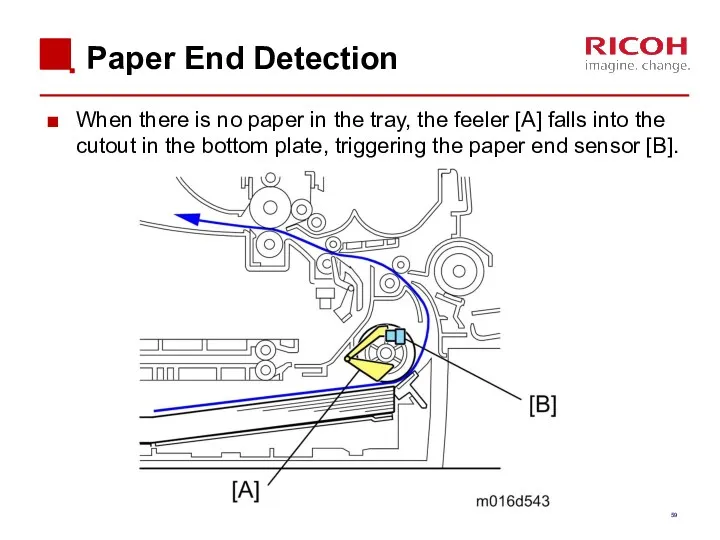
- 59. Paper End Detection When there is no paper in the tray, the feeler [A] falls into
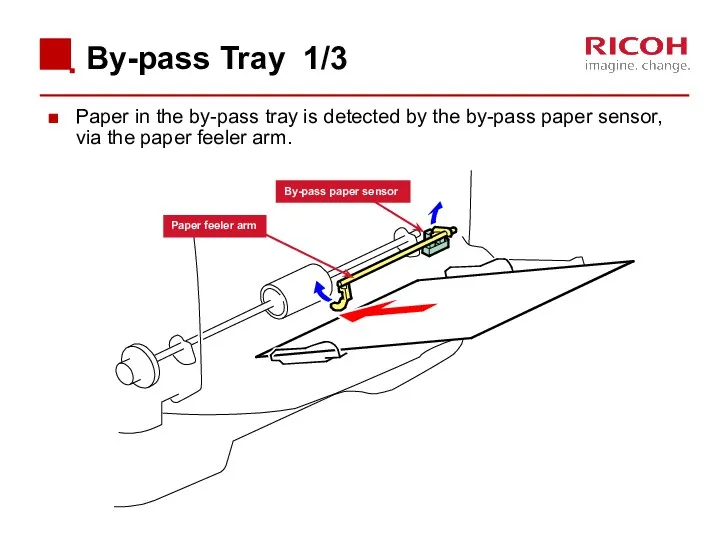
- 60. By-pass Tray 1/3 Paper in the by-pass tray is detected by the by-pass paper sensor, via
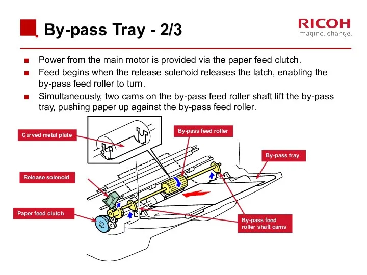
- 61. By-pass Tray - 2/3 Power from the main motor is provided via the paper feed clutch.
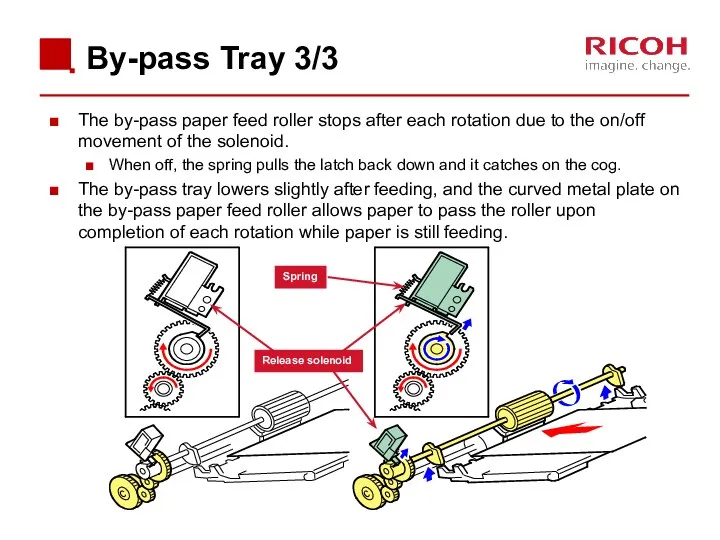
- 62. By-pass Tray 3/3 The by-pass paper feed roller stops after each rotation due to the on/off
- 63. 3.10 Fusing & Paper Exit
- 64. Overview Paper Exit Roller Hot Roller Strippers Thermostat Thermistor Fusing Lamp Hot Roller Paper Entrance Guide
- 65. Fusing Unit Layout Separation pads Paper exit sensor Hot roller Pressure roller Fusing lamp Cleaning roller
- 66. Fusing Drive The main motor drives the fusing unit through a gear train. Main motor Paper
- 67. Envelope Levers Envelope levers are provided on the right and left sides of the fusing unit.
- 68. Fusing Temperature Control When the main switch is turned on, the CPU turns on the fusing
- 69. Overheat Protection When hot roller temperature becomes greater than 225°C, the CPU cuts off power to
- 70. Paper Exit The paper exit guide plate holds down the trailing edge of each sheet of
- 71. 3.11 Duplex
- 72. Paper Path [A]: Duplex section [B]: Paper tray
- 73. Duplex Sensors Relay sensor Paper exit sensor Inverter sensor Registration sensor
- 74. Paper from the registration roller is sent to the paper exit roller. The duplex motor controls
- 75. Duplex Details 2/2 When the trailing edge of the paper passes the relay sensor, the paper
- 76. Interleaving Two sheets can be fed at the same time.
- 77. 4. Troubleshooting
- 78. Paper Jams Various types of paper jams and their causes are detailed in the service manual.
- 79. Printed Image Issues When abnormal image (black or white dots) appears at certain intervals, component part
- 80. Test Pattern Printing Test Pattern Printing - When checking an image or other problems, it might
- 82. Скачать презентацию
Objectives
After completing this training you should be able to:
Install the Remy-MF1/P1
Objectives
After completing this training you should be able to:
Install the Remy-MF1/P1
Requirements
Remy MF1/P1
Windows PC
Printer Drivers
Field Service Manual
Operation Manual
This presentation
Requirements
Remy MF1/P1
Windows PC
Printer Drivers
Field Service Manual
Operation Manual
This presentation

Pre-requisites and exam
Before starting this training you must already have followed
Pre-requisites and exam
Before starting this training you must already have followed
Module overview
Introduction
Maintenance
Detailed Section Descriptions
Troubleshooting
Module overview
Introduction
Maintenance
Detailed Section Descriptions
Troubleshooting

1. Introduction
1. Introduction
Remy models
Remy-MF1a
M156: SP 311SFN
Remy-MF1aw
M157: SP 311SFNw
Remy-P1a
M154: SP 311DN
Remy-P1aw
M155: SP 311DNw
Common items
Remy models
Remy-MF1a
M156: SP 311SFN
Remy-MF1aw
M157: SP 311SFNw
Remy-P1a
M154: SP 311DN
Remy-P1aw
M155: SP 311DNw
Common items
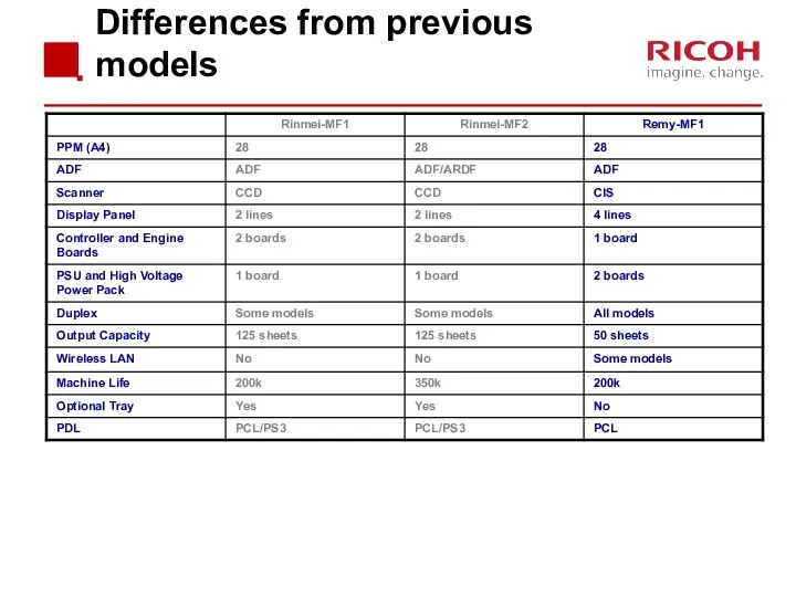
Differences from previous models
Differences from previous models
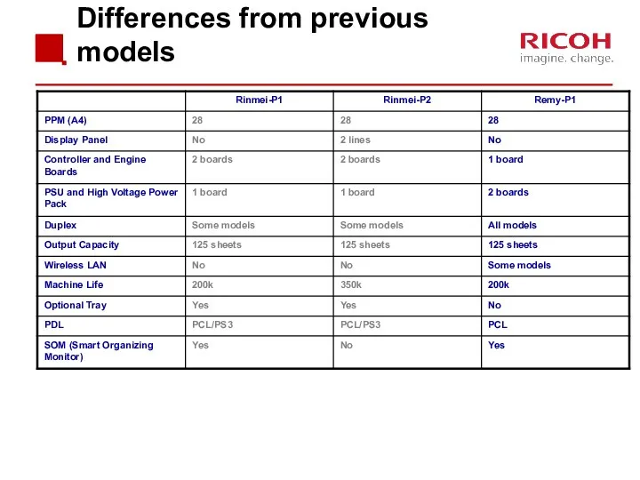
Differences from previous models
Differences from previous models
Other Points
Remy-MF1/P1 do not have a USB host or the scan
Other Points
Remy-MF1/P1 do not have a USB host or the scan
AIO Cartridges
There are 3 types of AIO cartridges:
Starter AIO: 1k per
AIO Cartridges
There are 3 types of AIO cartridges:
Starter AIO: 1k per
Targets
Monthly Print Volume
Average: 0.7K
Maximum: 5.8K
Estimated Unit Life: 5 years
Targets
Monthly Print Volume
Average: 0.7K
Maximum: 5.8K
Estimated Unit Life: 5 years

2. Maintenance
2. Maintenance
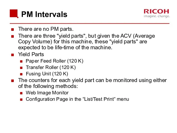
PM Intervals
There are no PM parts.
There are three "yield parts", but
PM Intervals
There are no PM parts.
There are three "yield parts", but
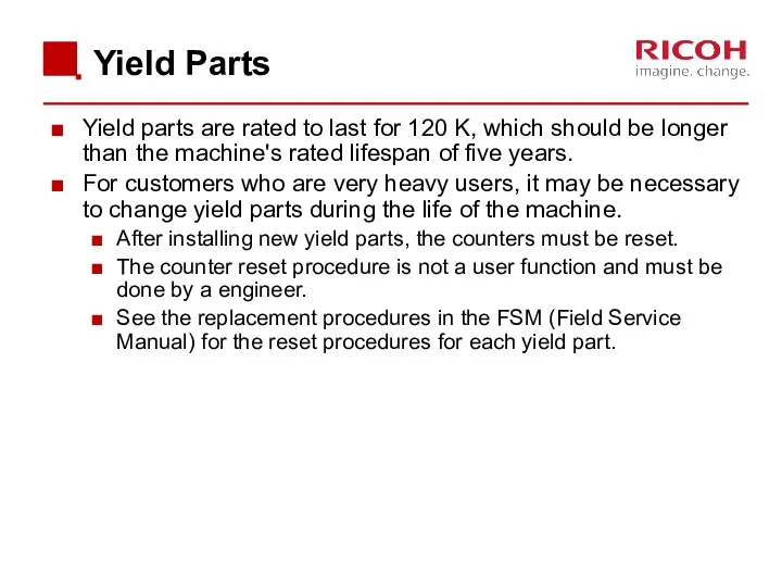
Yield Parts
Yield parts are rated to last for 120 K, which
Yield Parts
Yield parts are rated to last for 120 K, which
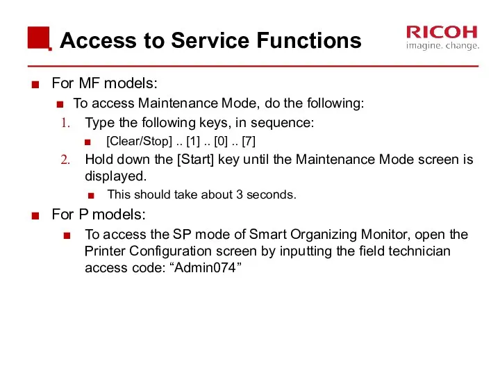
Access to Service Functions
For MF models:
To access Maintenance Mode, do
Access to Service Functions
For MF models:
To access Maintenance Mode, do
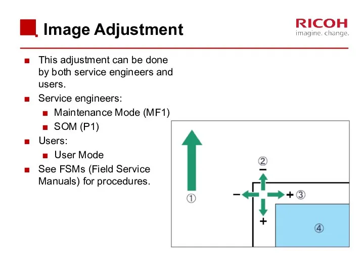
Image Adjustment
This adjustment can be done by both service engineers and
Image Adjustment
This adjustment can be done by both service engineers and
Firmware Updating
You need a PC to do the firmware update.
See the
Firmware Updating
You need a PC to do the firmware update.
See the

3. Detailed Section Descriptions
3. Detailed Section Descriptions

3.1 Machine Overview
3.1 Machine Overview
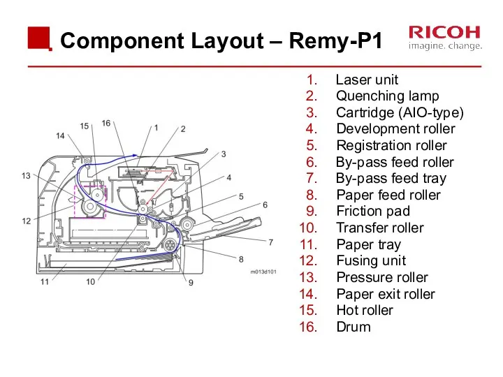
Component Layout – Remy-P1
Laser unit
Quenching lamp
Cartridge (AIO-type)
Development roller
Registration roller
By-pass feed roller
By-pass
Component Layout – Remy-P1
Laser unit
Quenching lamp
Cartridge (AIO-type)
Development roller
Registration roller
By-pass feed roller
By-pass
![Paper Path – Remy-P1 [A]: Duplex section [B]: Paper tray](/_ipx/f_webp&q_80&fit_contain&s_1440x1080/imagesDir/jpg/376521/slide-21.jpg)
Paper Path – Remy-P1
[A]: Duplex section
[B]: Paper tray
Paper Path – Remy-P1
[A]: Duplex section
[B]: Paper tray
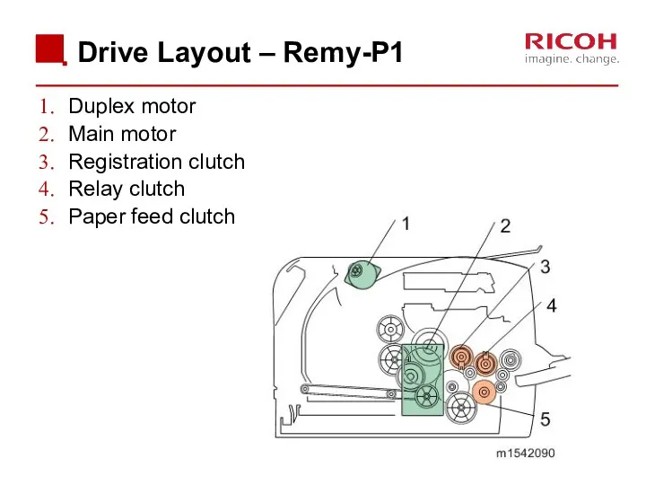
Drive Layout – Remy-P1
Duplex motor
Main motor
Registration clutch
Relay clutch
Paper feed clutch
Drive Layout – Remy-P1
Duplex motor
Main motor
Registration clutch
Relay clutch
Paper feed clutch

3.2 Cover Removal & Part Replacement
3.2 Cover Removal & Part Replacement
General Precautions
Before you start to work on the machine:
If there are
General Precautions
Before you start to work on the machine:
If there are
General Precautions
Many of the parts are held in place with plastic
General Precautions
Many of the parts are held in place with plastic

Removing Covers
The covers have a lot of hooks and tabs.
Disconnect these
Removing Covers
The covers have a lot of hooks and tabs.
Disconnect these
Re-installing the Top Cover
When re-installing the top cover, always verify that
Re-installing the Top Cover
When re-installing the top cover, always verify that
Replacing the Main Board
Do not connect any connectors to JRS1 and
Replacing the Main Board
Do not connect any connectors to JRS1 and
Install a New EEPROM
Do the following settings after installing a new
Install a New EEPROM
Do the following settings after installing a new

3.3 ADF
3.3 ADF
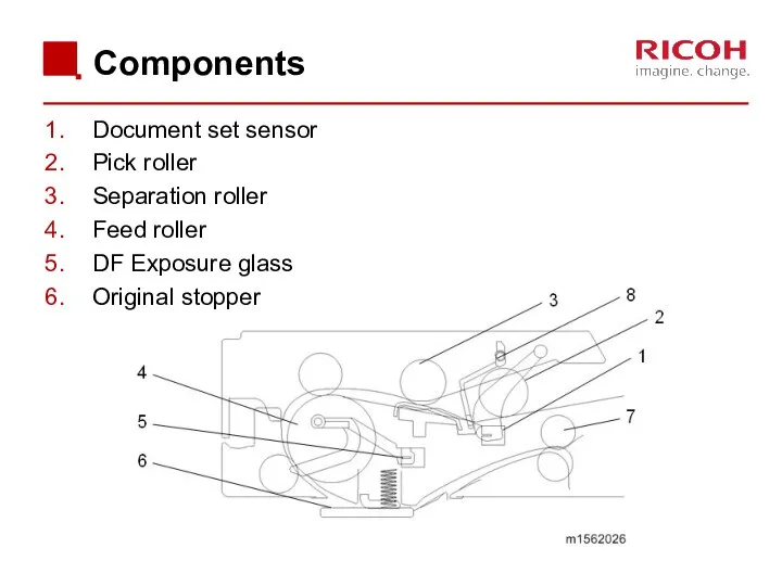
Components
Document set sensor
Pick roller
Separation roller
Feed roller
DF Exposure glass
Original stopper
Components
Document set sensor
Pick roller
Separation roller
Feed roller
DF Exposure glass
Original stopper
![Paper Path When the document set sensor [1] detects an](/_ipx/f_webp&q_80&fit_contain&s_1440x1080/imagesDir/jpg/376521/slide-32.jpg)
Paper Path
When the document set sensor [1] detects an original, the
Paper Path
When the document set sensor [1] detects an original, the

3.4 Scanner
3.4 Scanner
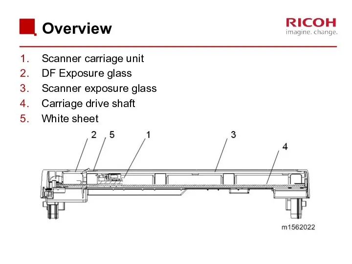
Overview
Scanner carriage unit
DF Exposure glass
Scanner exposure glass
Carriage drive shaft
White sheet
Overview
Scanner carriage unit
DF Exposure glass
Scanner exposure glass
Carriage drive shaft
White sheet
![Drive Scanner motor [A]: Drives the scanner carriage unit [B]](/_ipx/f_webp&q_80&fit_contain&s_1440x1080/imagesDir/jpg/376521/slide-35.jpg)
Drive
Scanner motor [A]: Drives the scanner carriage unit [B] through gears
Drive
Scanner motor [A]: Drives the scanner carriage unit [B] through gears

3.5 Laser Exposure
3.5 Laser Exposure
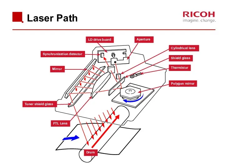
Laser Path
Polygon mirror
LD drive board
Synchronization detector
Aperture
Cylindrical lens
Shield glass
Thermistor
Drum
FTL Lens
Toner shield glass
Mirror
Laser Path
Polygon mirror
LD drive board
Synchronization detector
Aperture
Cylindrical lens
Shield glass
Thermistor
Drum
FTL Lens
Toner shield glass
Mirror
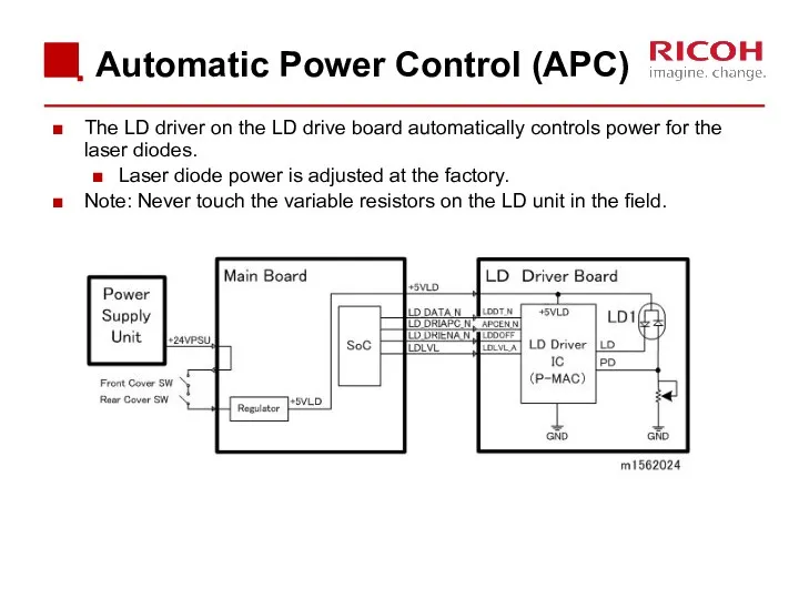
Automatic Power Control (APC)
The LD driver on the LD drive board
Automatic Power Control (APC)
The LD driver on the LD drive board
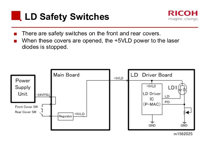
LD Safety Switches
There are safety switches on the front and rear
LD Safety Switches
There are safety switches on the front and rear

3.6 AIO
3.6 AIO
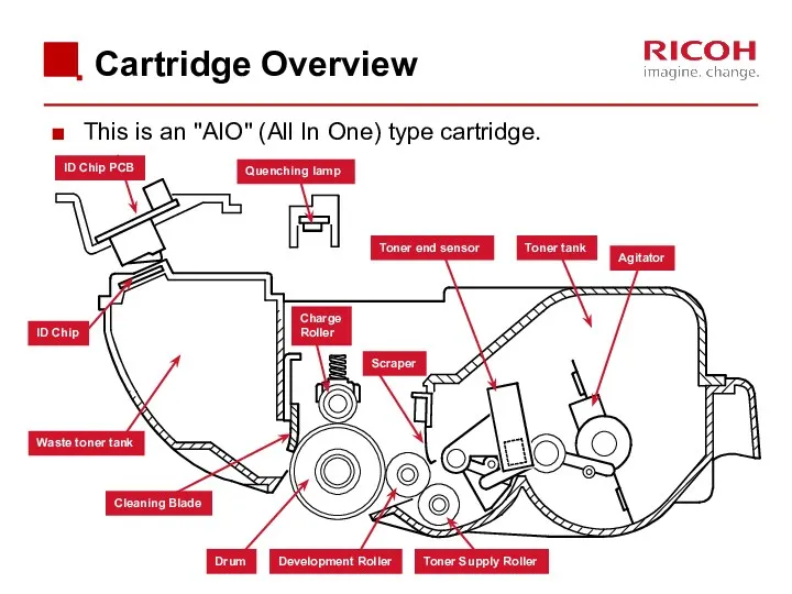
Cartridge Overview
This is an "AIO" (All In One) type cartridge.
Quenching lamp
Waste
Cartridge Overview
This is an "AIO" (All In One) type cartridge.
Quenching lamp
Waste
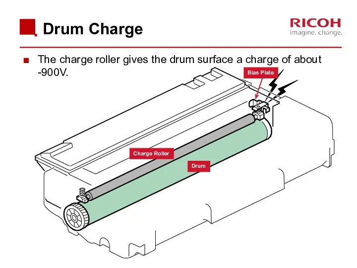
Drum Charge
The charge roller gives the drum surface a charge of
Drum Charge
The charge roller gives the drum surface a charge of

3.7 Toner Supply and Development
3.7 Toner Supply and Development
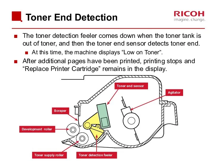
Toner End Detection
The toner detection feeler comes down when the toner
Toner End Detection
The toner detection feeler comes down when the toner
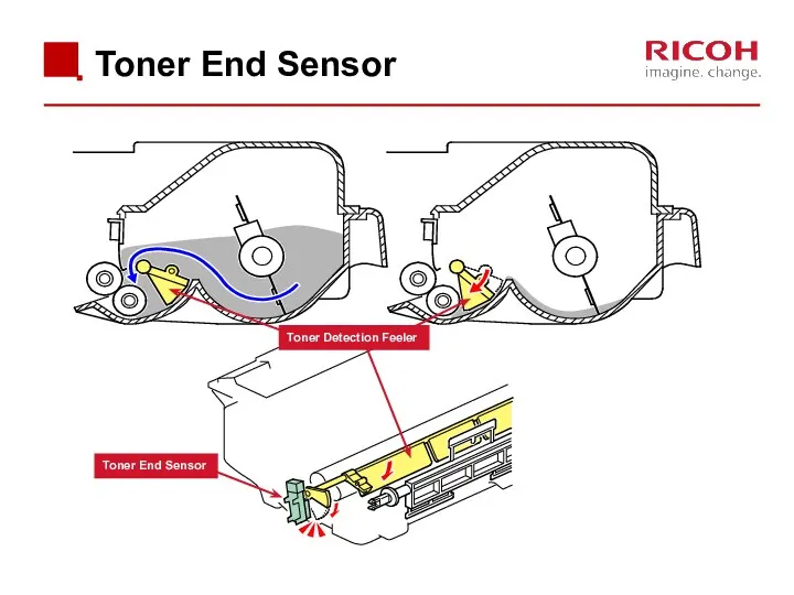
Toner End Sensor
Toner End Sensor
Toner Detection Feeler
Toner End Sensor
Toner End Sensor
Toner Detection Feeler
Toner Overflow Prevention 1/2
Main Motor Rotation Count
Time to replace the AIO
Toner Overflow Prevention 1/2
Main Motor Rotation Count
Time to replace the AIO
Toner Overflow Prevention 2/2
Why do we need this feature?
Normally, the AIO
Toner Overflow Prevention 2/2
Why do we need this feature?
Normally, the AIO
AIO Replacement
The new AIO is detected by the machine with the
AIO Replacement
The new AIO is detected by the machine with the
3.8 Transfer & Separation
3.8 Transfer & Separation
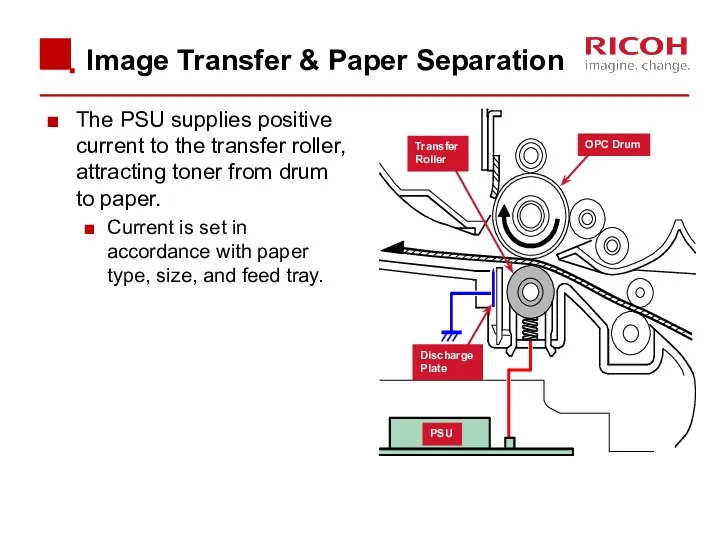
Image Transfer & Paper Separation
The PSU supplies positive current to the
Image Transfer & Paper Separation
The PSU supplies positive current to the
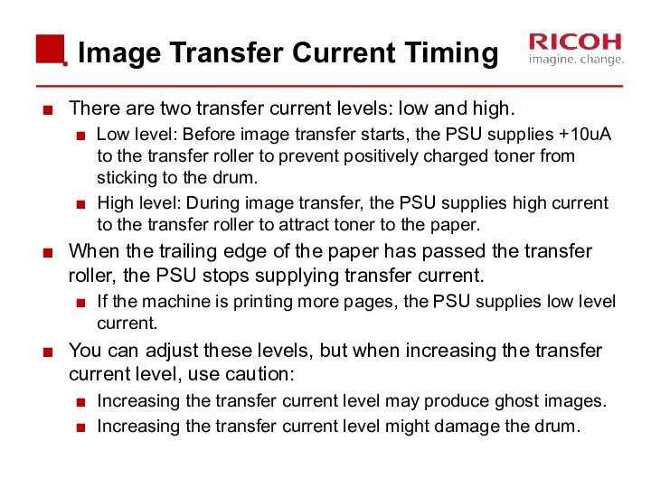
Image Transfer Current Timing
There are two transfer current levels: low and
Image Transfer Current Timing
There are two transfer current levels: low and
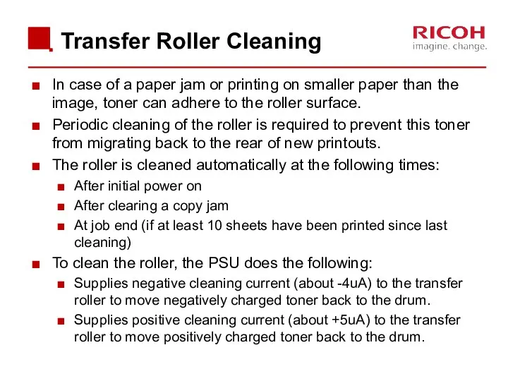
Transfer Roller Cleaning
In case of a paper jam or printing on
Transfer Roller Cleaning
In case of a paper jam or printing on

3.9 Paper Feed
3.9 Paper Feed
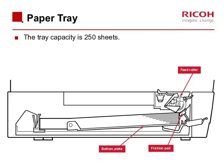
Paper Tray
The tray capacity is 250 sheets.
Feed roller
Friction pad
Bottom plate
Paper Tray
The tray capacity is 250 sheets.
Feed roller
Friction pad
Bottom plate
![Paper Path [A]: Duplex section [B]: Paper tray](/_ipx/f_webp&q_80&fit_contain&s_1440x1080/imagesDir/jpg/376521/slide-55.jpg)
Paper Path
[A]: Duplex section
[B]: Paper tray
Paper Path
[A]: Duplex section
[B]: Paper tray
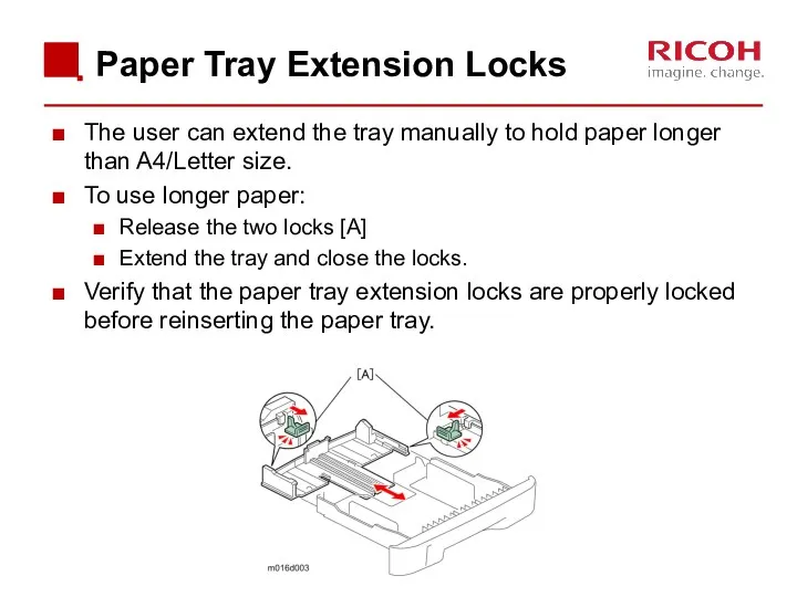
Paper Tray Extension Locks
The user can extend the tray manually to
Paper Tray Extension Locks
The user can extend the tray manually to
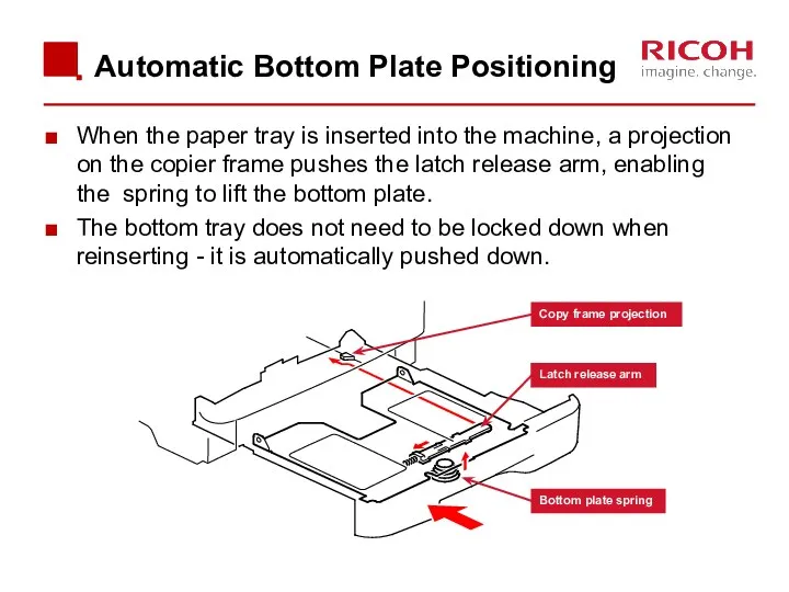
When the paper tray is inserted into the machine, a projection
When the paper tray is inserted into the machine, a projection
Paper End Detection
When there is no paper in the tray, the
Paper End Detection
When there is no paper in the tray, the
By-pass Tray 1/3
Paper in the by-pass tray is detected by the
By-pass Tray 1/3
Paper in the by-pass tray is detected by the
By-pass Tray - 2/3
Power from the main motor is provided via
By-pass Tray - 2/3
Power from the main motor is provided via
By-pass Tray 3/3
The by-pass paper feed roller stops after each rotation
By-pass Tray 3/3
The by-pass paper feed roller stops after each rotation

3.10 Fusing & Paper Exit
3.10 Fusing & Paper Exit
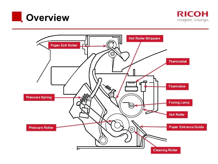
Overview
Paper Exit Roller
Hot Roller Strippers
Thermostat
Thermistor
Fusing Lamp
Hot Roller
Paper Entrance Guide
Cleaning Roller
Pressure Roller
Pressure
Overview
Paper Exit Roller
Hot Roller Strippers
Thermostat
Thermistor
Fusing Lamp
Hot Roller
Paper Entrance Guide
Cleaning Roller
Pressure Roller
Pressure
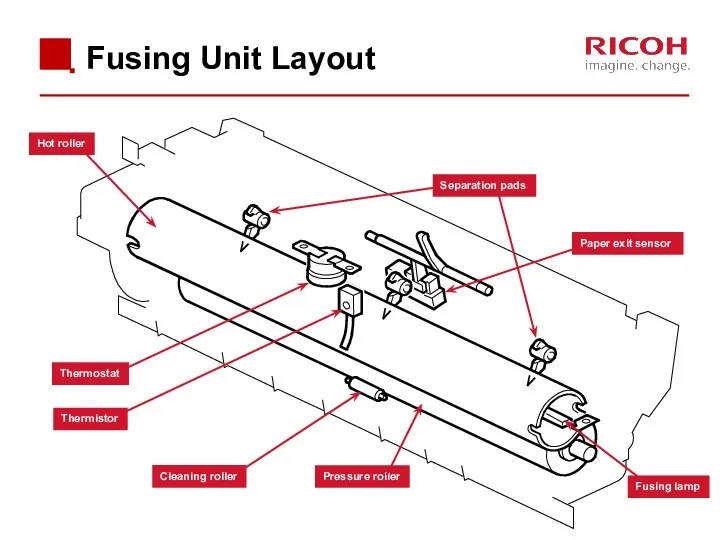
Fusing Unit Layout
Separation pads
Paper exit sensor
Hot roller
Pressure roller
Fusing lamp
Cleaning roller
Thermistor
Thermostat
Fusing Unit Layout
Separation pads
Paper exit sensor
Hot roller
Pressure roller
Fusing lamp
Cleaning roller
Thermistor
Thermostat
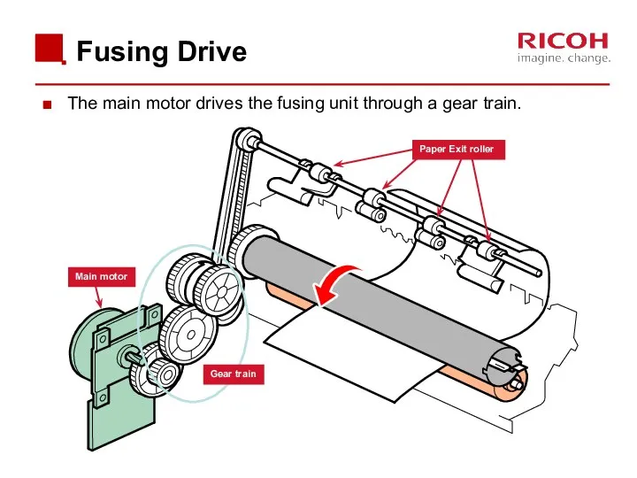
Fusing Drive
The main motor drives the fusing unit through a gear
Fusing Drive
The main motor drives the fusing unit through a gear
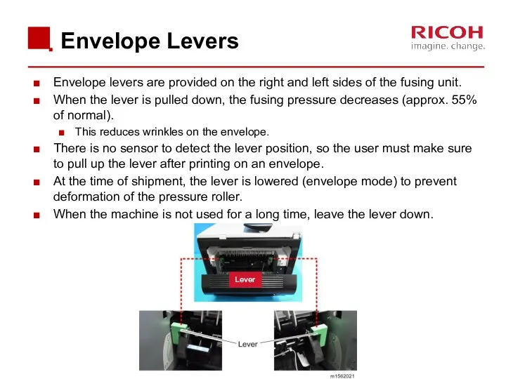
Envelope Levers
Envelope levers are provided on the right and left sides
Envelope Levers
Envelope levers are provided on the right and left sides
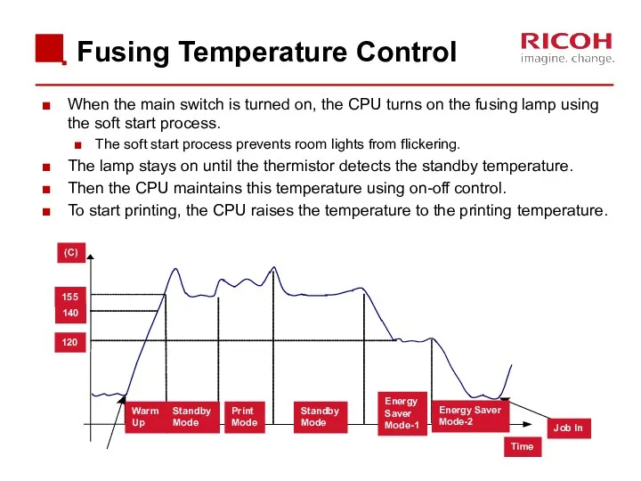
Fusing Temperature Control
When the main switch is turned on, the CPU
Fusing Temperature Control
When the main switch is turned on, the CPU

Overheat Protection
When hot roller temperature becomes greater than 225°C, the CPU
Overheat Protection
When hot roller temperature becomes greater than 225°C, the CPU
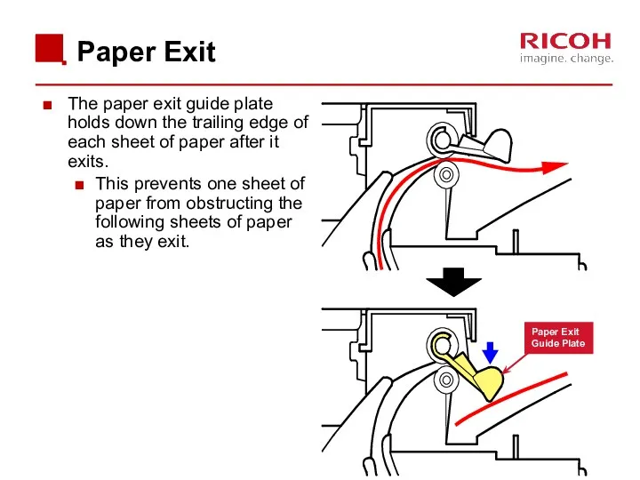
Paper Exit
The paper exit guide plate holds down the trailing edge
Paper Exit
The paper exit guide plate holds down the trailing edge

3.11 Duplex
3.11 Duplex
![Paper Path [A]: Duplex section [B]: Paper tray](/_ipx/f_webp&q_80&fit_contain&s_1440x1080/imagesDir/jpg/376521/slide-71.jpg)
Paper Path
[A]: Duplex section
[B]: Paper tray
Paper Path
[A]: Duplex section
[B]: Paper tray
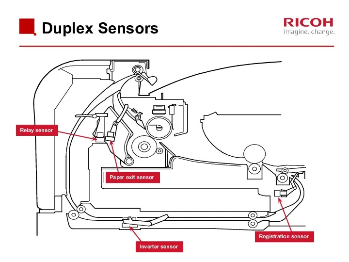
Duplex Sensors
Relay sensor
Paper exit sensor
Inverter sensor
Registration sensor
Duplex Sensors
Relay sensor
Paper exit sensor
Inverter sensor
Registration sensor
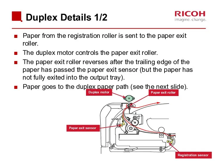
Paper from the registration roller is sent to the paper exit
Paper from the registration roller is sent to the paper exit
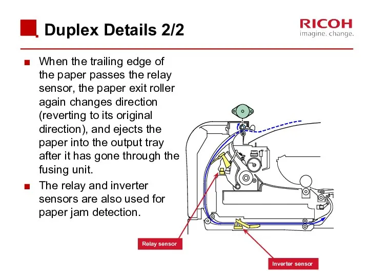
Duplex Details 2/2
When the trailing edge of the paper passes the
Duplex Details 2/2
When the trailing edge of the paper passes the
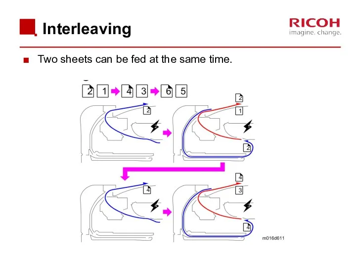
Interleaving
Two sheets can be fed at the same time.
Interleaving
Two sheets can be fed at the same time.
4. Troubleshooting
4. Troubleshooting
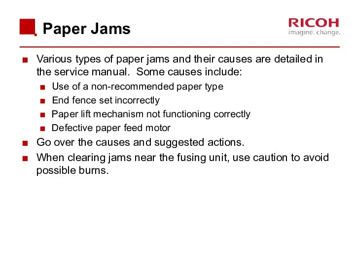
Paper Jams
Various types of paper jams and their causes are detailed
Paper Jams
Various types of paper jams and their causes are detailed
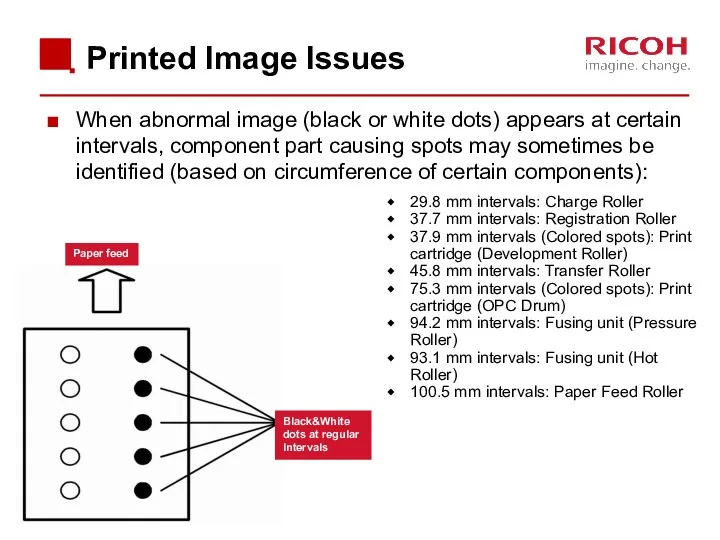
Printed Image Issues
When abnormal image (black or white dots) appears at
Printed Image Issues
When abnormal image (black or white dots) appears at
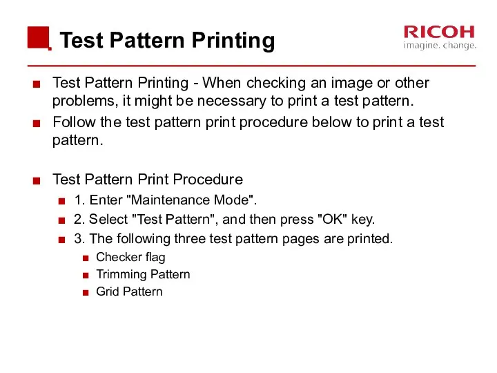
Test Pattern Printing
Test Pattern Printing - When checking an image or
Test Pattern Printing
Test Pattern Printing - When checking an image or
 Парадигмы программирования 2024 ОАиП
 HTML. Введение в CSS. Подготовка графики
 Основные этапы моделирования
 Создание и редактирование фона. Работа с сенсорами. Создание собственного мини-проекта
 Система управління мережами наступного покоління
 Интеллектуальный анализ данных Data Mining
 Информация и подходы к ее количественной оценке
 Особенности оформления и верстки газет
 Онлайн-СМИ России
 Операційні системи. Керування введенням-виведенням
 Деловая графика
 Логические законы и правила преобразования логических выражений
 Что такое интерактивные игры
 Решение задач части В демоверсии ЕГЭ-2013 по информатике
 Учебно-методическое пособие Исполнитель Робот в программе КуМир
 Introduction to computer systems. Architecture of computer systems
 Решение логических задач
 Архитектура ЭВМ и вычислительных систем
 Введение в функциональное тестирование
 Поиск медицинской информации. Источники, возможности, лайфхаки
 Основы языка SQL
 Введение в тестирование (занятие 1)
 JavaScript: функциялар
 Компьютерные сети. Локальные. Глобальные
 Бездротові мережі
 ОС вопросы1_12
 Криптографические методы защиты информации. Перспективные направления разработок
 Облачные технологии