- Combinational logic design

Содержание
- 2. Introduction Boolean Equations Boolean Algebra From Logic to Gates Multilevel Combinational Logic X’s and Z’s, Oh
- 3. A logic circuit is composed of: Inputs Outputs Functional specification Timing specification Introduction
- 4. Nodes Inputs: A, B, C Outputs: Y, Z Internal: n1 Circuit elements E1, E2, E3 Each
- 5. Combinational Logic Memoryless Outputs determined by current values of inputs Sequential Logic Has memory Outputs determined
- 6. Every element is combinational Every node is either an input or connects to exactly one output
- 7. Functional specification of outputs in terms of inputs Example: S = F(A, B, Cin) Cout =
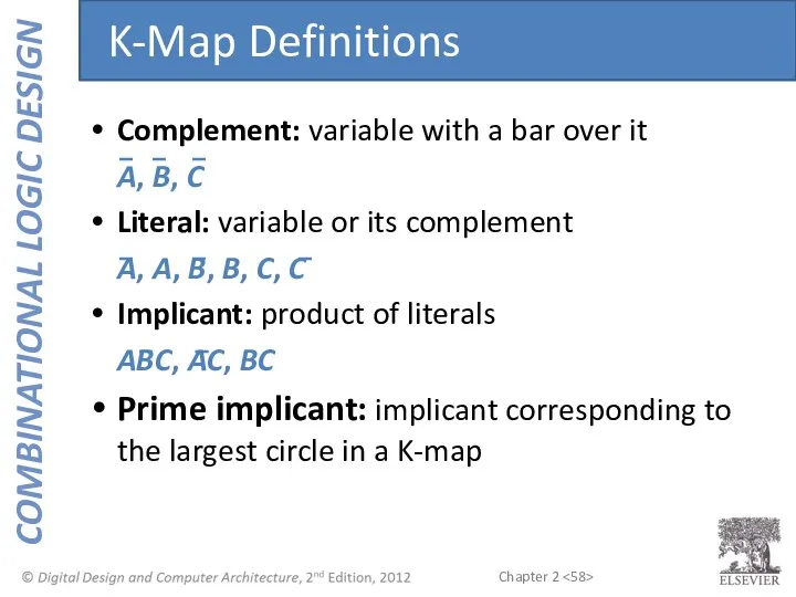
- 8. Complement: variable with a bar over it A, B, C Literal: variable or its complement A,
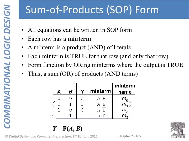
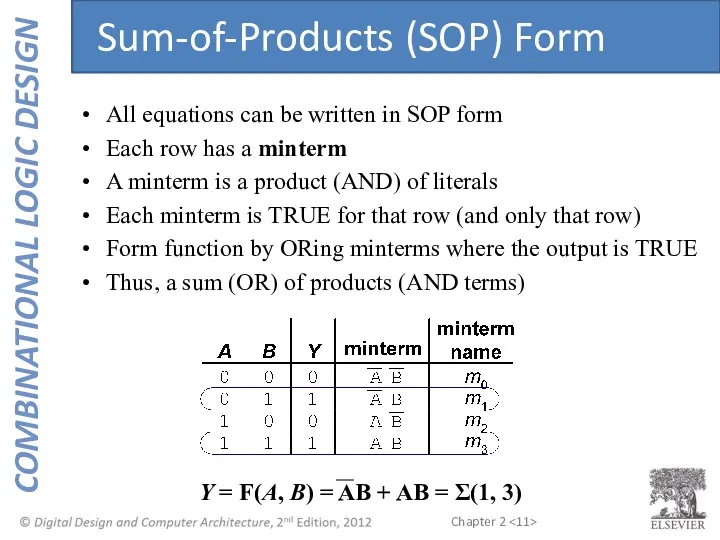
- 9. Y = F(A, B) = All equations can be written in SOP form Each row has
- 10. Y = F(A, B) = Sum-of-Products (SOP) Form All equations can be written in SOP form
- 11. Y = F(A, B) = AB + AB = Σ(1, 3) Sum-of-Products (SOP) Form All equations
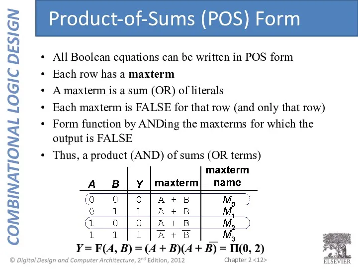
- 12. Y = F(A, B) = (A + B)(A + B) = Π(0, 2) All Boolean equations
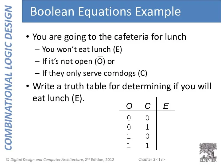
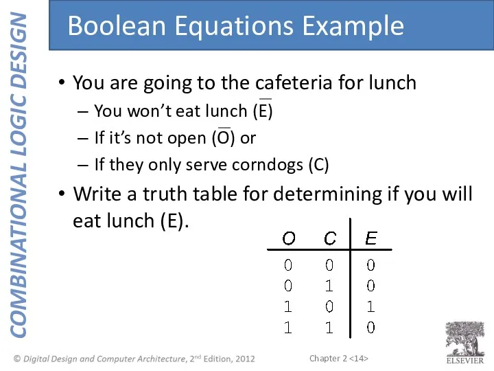
- 13. You are going to the cafeteria for lunch You won’t eat lunch (E) If it’s not
- 14. You are going to the cafeteria for lunch You won’t eat lunch (E) If it’s not
- 15. SOP & POS Form SOP – sum-of-products POS – product-of-sums
- 16. SOP – sum-of-products POS – product-of-sums E = (O + C)(O + C)(O + C) =
- 17. Axioms and theorems to simplify Boolean equations Like regular algebra, but simpler: variables have only two
- 18. Boolean Axioms
- 19. B 1 = B B + 0 = B T1: Identity Theorem
- 20. B 1 = B B + 0 = B T1: Identity Theorem
- 21. B 0 = 0 B + 1 = 1 T2: Null Element Theorem
- 22. B 0 = 0 B + 1 = 1 T2: Null Element Theorem
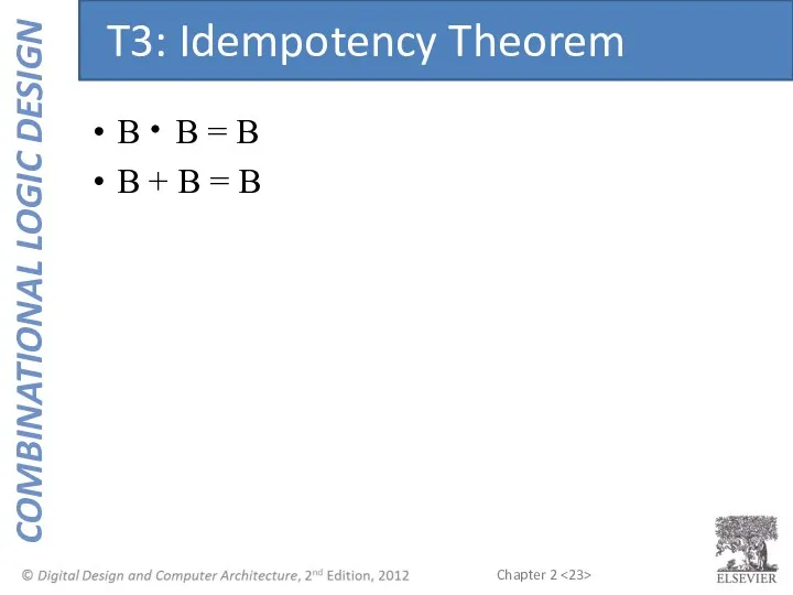
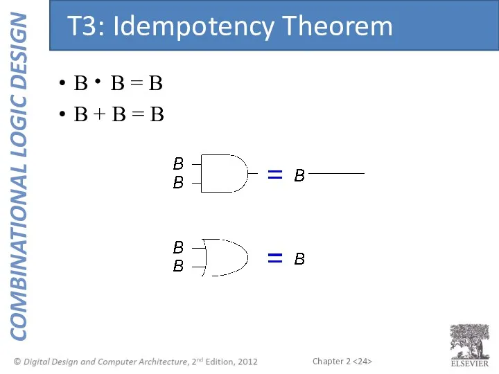
- 23. B B = B B + B = B T3: Idempotency Theorem
- 24. B B = B B + B = B T3: Idempotency Theorem
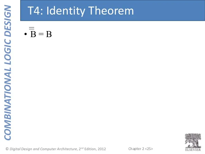
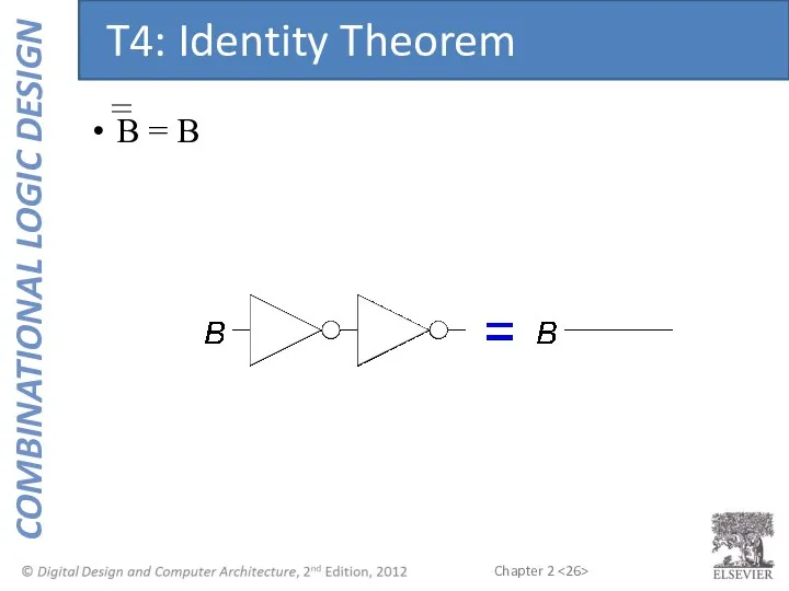
- 25. B = B T4: Identity Theorem
- 26. B = B T4: Identity Theorem
- 27. B B = 0 B + B = 1 T5: Complement Theorem
- 28. B B = 0 B + B = 1 T5: Complement Theorem
- 29. Boolean Theorems Summary
- 30. Boolean Theorems of Several Vars Note: T8’ differs from traditional algebra: OR (+) distributes over AND
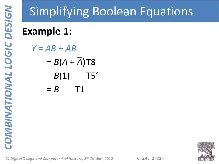
- 31. Y = AB + AB Simplifying Boolean Equations Example 1:
- 32. Y = AB + AB = B(A + A) T8 = B(1) T5’ = B T1
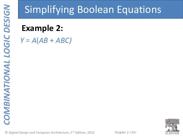
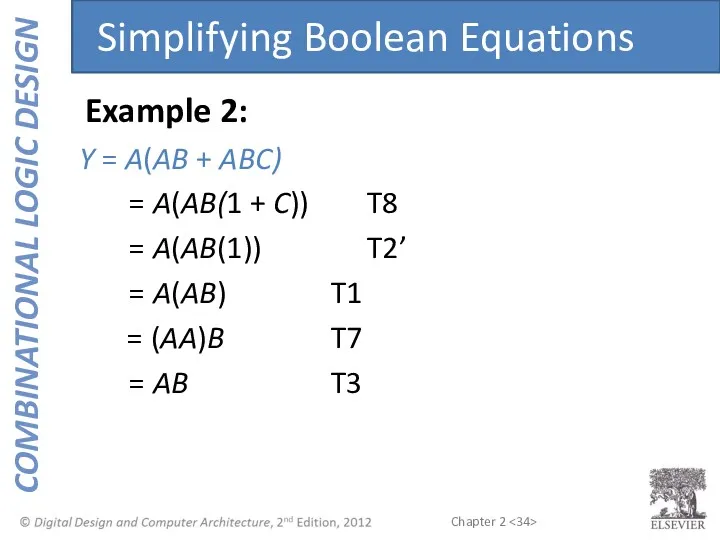
- 33. Y = A(AB + ABC) Example 2: Simplifying Boolean Equations
- 34. Y = A(AB + ABC) = A(AB(1 + C)) T8 = A(AB(1)) T2’ = A(AB) T1
- 35. Y = AB = A + B Y = A + B = A B DeMorgan’s
- 36. Backward: Body changes Adds bubbles to inputs Forward: Body changes Adds bubble to output Bubble Pushing
- 37. What is the Boolean expression for this circuit? Bubble Pushing
- 38. What is the Boolean expression for this circuit? Y = AB + CD Bubble Pushing
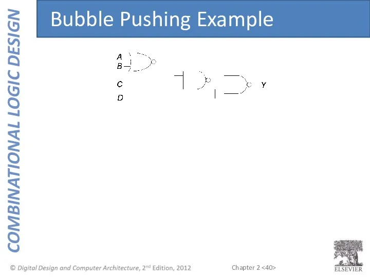
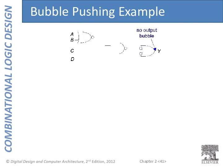
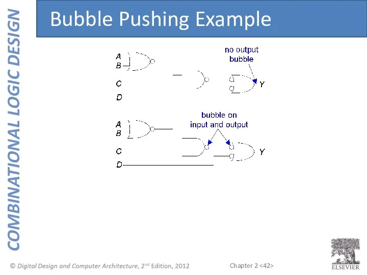
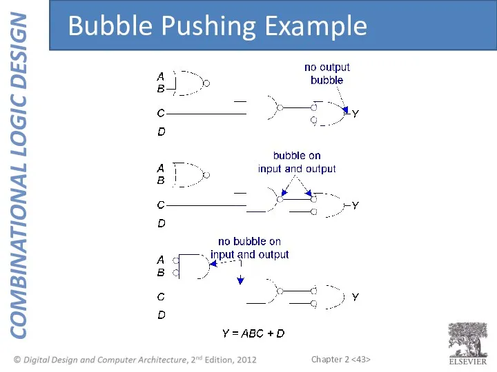
- 39. Begin at output, then work toward inputs Push bubbles on final output back Draw gates in
- 40. Bubble Pushing Example
- 41. Bubble Pushing Example
- 42. Bubble Pushing Example
- 43. Bubble Pushing Example
- 44. Two-level logic: ANDs followed by ORs Example: Y = ABC + ABC + ABC From Logic
- 45. Inputs on the left (or top) Outputs on right (or bottom) Gates flow from left to
- 46. Wires always connect at a T junction A dot where wires cross indicates a connection between
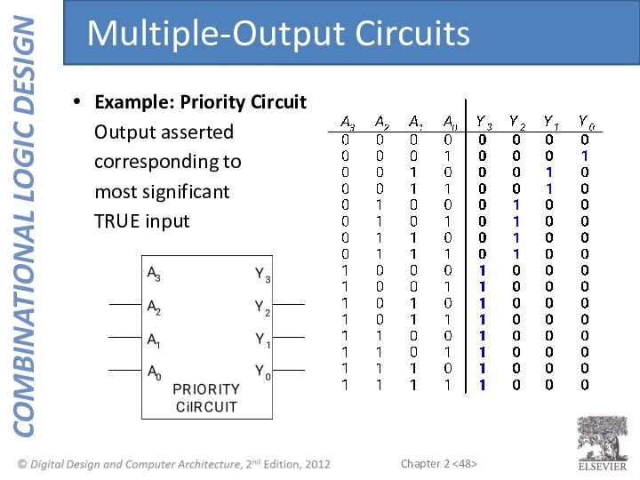
- 47. Example: Priority Circuit Output asserted corresponding to most significant TRUE input Multiple-Output Circuits
- 48. Example: Priority Circuit Output asserted corresponding to most significant TRUE input Multiple-Output Circuits
- 49. Priority Circuit Hardware
- 50. Don’t Cares
- 51. Contention: circuit tries to drive output to 1 and 0 Actual value somewhere in between Could
- 52. Floating, high impedance, open, high Z Floating output might be 0, 1, or somewhere in between
- 53. Floating nodes are used in tristate busses Many different drivers Exactly one is active at once
- 54. Boolean expressions can be minimized by combining terms K-maps minimize equations graphically PA + PA =
- 55. Circle 1’s in adjacent squares In Boolean expression, include only literals whose true and complement form
- 56. 3-Input K-Map
- 57. Y = AB + BC 3-Input K-Map
- 58. Complement: variable with a bar over it A, B, C Literal: variable or its complement A,
- 59. Every 1 must be circled at least once Each circle must span a power of 2
- 60. 4-Input K-Map
- 61. 4-Input K-Map
- 62. 4-Input K-Map
- 63. K-Maps with Don’t Cares
- 64. K-Maps with Don’t Cares
- 65. K-Maps with Don’t Cares
- 66. Multiplexers Decoders Combinational Building Blocks
- 67. Selects between one of N inputs to connect to output log2N-bit select input – control input
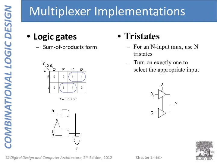
- 68. 2- Logic gates Sum-of-products form Tristates For an N-input mux, use N tristates Turn on exactly
- 69. Using the mux as a lookup table Logic using Multiplexers
- 70. Reducing the size of the mux Logic using Multiplexers
- 71. N inputs, 2N outputs One-hot outputs: only one output HIGH at once Decoders
- 72. Decoder Implementation
- 73. OR minterms Logic Using Decoders
- 74. ENOUGH FOR TODAY!
- 75. Delay between input change and output changing How to build fast circuits? Timing
- 76. Propagation delay: tpd = max delay from input to output Contamination delay: tcd = min delay
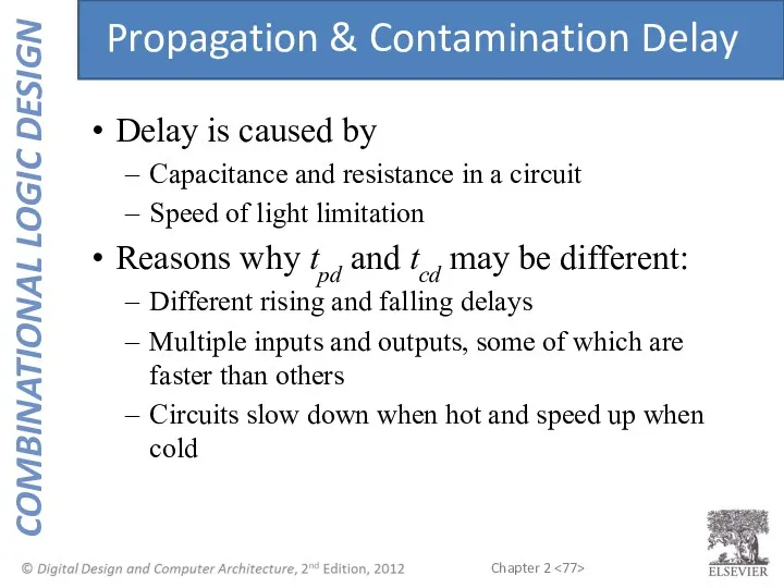
- 77. Delay is caused by Capacitance and resistance in a circuit Speed of light limitation Reasons why
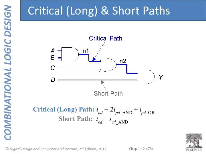
- 78. Critical (Long) Path: tpd = 2tpd_AND + tpd_OR Short Path: tcd = tcd_AND Critical (Long) &
- 79. When a single input change causes an output to change multiple times Glitches
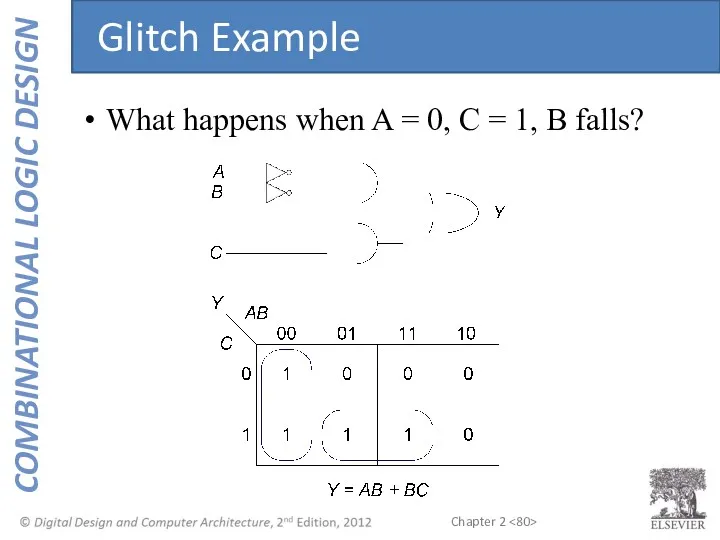
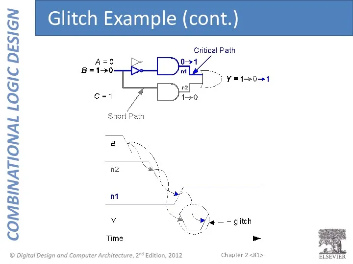
- 80. What happens when A = 0, C = 1, B falls? Glitch Example
- 81. Glitch Example (cont.)
- 82. Fixing the Glitch
- 84. Скачать презентацию
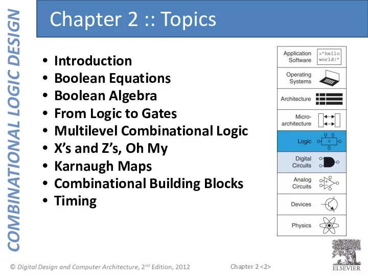
Introduction
Boolean Equations
Boolean Algebra
From Logic to Gates
Multilevel Combinational Logic
X’s and Z’s, Oh
Introduction
Boolean Equations
Boolean Algebra
From Logic to Gates
Multilevel Combinational Logic
X’s and Z’s, Oh
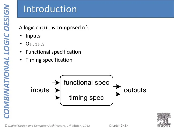
A logic circuit is composed of:
Inputs
Outputs
Functional specification
Timing specification
Introduction
A logic circuit is composed of:
Inputs
Outputs
Functional specification
Timing specification
Introduction
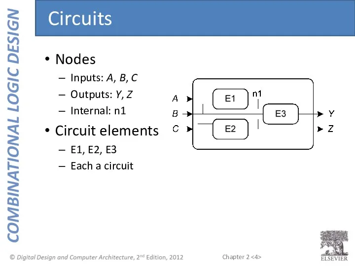
Nodes
Inputs: A, B, C
Outputs: Y, Z
Internal: n1
Circuit elements
E1, E2, E3
Each a
Nodes
Inputs: A, B, C
Outputs: Y, Z
Internal: n1
Circuit elements
E1, E2, E3
Each a
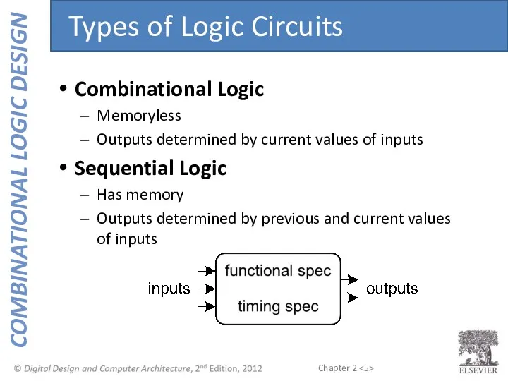
Combinational Logic
Memoryless
Outputs determined by current values of inputs
Sequential Logic
Has memory
Outputs determined
Combinational Logic
Memoryless
Outputs determined by current values of inputs
Sequential Logic
Has memory
Outputs determined
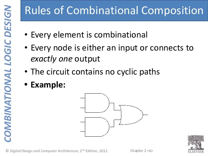
Every element is combinational
Every node is either an input or connects
Every element is combinational
Every node is either an input or connects
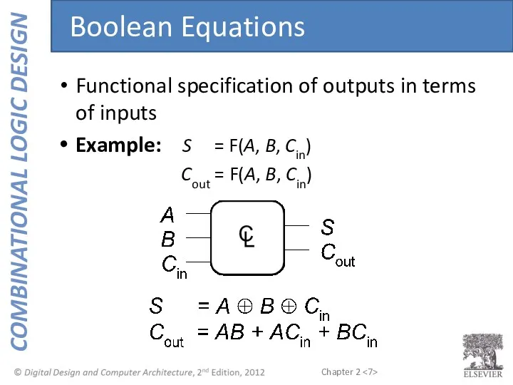
Functional specification of outputs in terms of inputs
Example: S = F(A,
Functional specification of outputs in terms of inputs
Example: S = F(A,
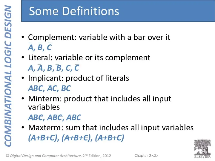
Complement: variable with a bar over it
A, B, C
Literal: variable
Complement: variable with a bar over it
A, B, C
Literal: variable

Y = F(A, B) =
All equations can be written in SOP
Y = F(A, B) =
All equations can be written in SOP
Y = F(A, B) =
Sum-of-Products (SOP) Form
All equations can be written
Y = F(A, B) =
Sum-of-Products (SOP) Form
All equations can be written
Y = F(A, B) = AB + AB = Σ(1, 3)
Sum-of-Products
Y = F(A, B) = AB + AB = Σ(1, 3)
Sum-of-Products
Y = F(A, B) = (A + B)(A + B) =
Y = F(A, B) = (A + B)(A + B) =
You are going to the cafeteria for lunch
You won’t eat lunch
You are going to the cafeteria for lunch
You won’t eat lunch
You are going to the cafeteria for lunch
You won’t eat lunch
You are going to the cafeteria for lunch
You won’t eat lunch
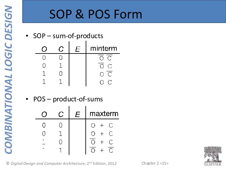
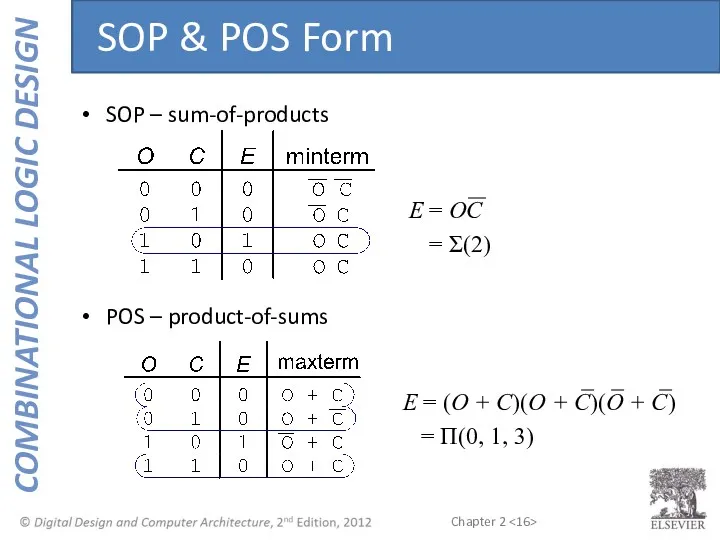
SOP & POS Form
SOP – sum-of-products
POS – product-of-sums
SOP & POS Form
SOP – sum-of-products
POS – product-of-sums
SOP – sum-of-products
POS – product-of-sums
E = (O + C)(O + C)(O
SOP – sum-of-products
POS – product-of-sums
E = (O + C)(O + C)(O
Axioms and theorems to simplify Boolean equations
Like regular algebra, but simpler:
Axioms and theorems to simplify Boolean equations
Like regular algebra, but simpler:
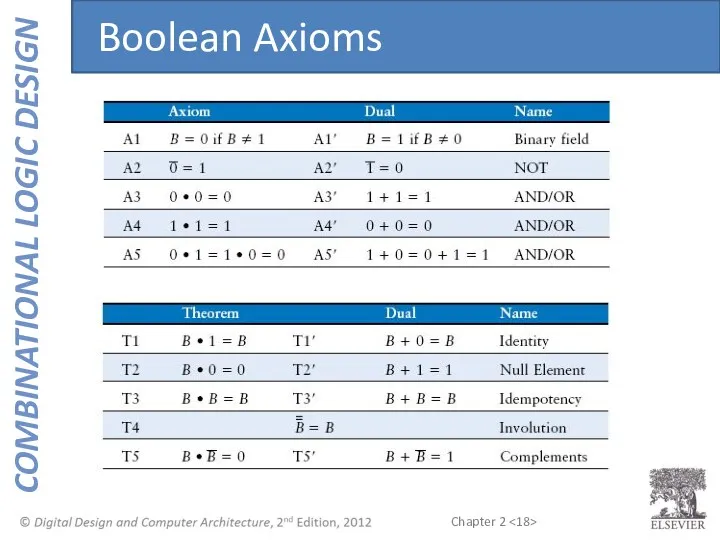
Boolean Axioms
Boolean Axioms
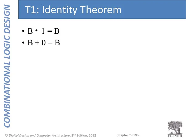
B 1 = B
B + 0 = B
T1: Identity Theorem
B 1 = B
B + 0 = B
T1: Identity Theorem
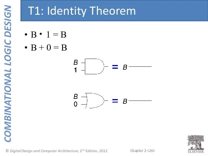
B 1 = B
B + 0 = B
T1: Identity Theorem
B 1 = B
B + 0 = B
T1: Identity Theorem
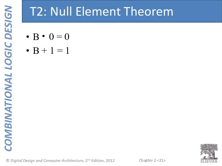
B 0 = 0
B + 1 = 1
T2: Null Element Theorem
B 0 = 0
B + 1 = 1
T2: Null Element Theorem
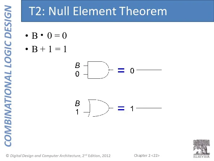
B 0 = 0
B + 1 = 1
T2: Null Element Theorem
B 0 = 0
B + 1 = 1
T2: Null Element Theorem
B B = B
B + B = B
T3: Idempotency Theorem
B B = B
B + B = B
T3: Idempotency Theorem
B B = B
B + B = B
T3: Idempotency Theorem
B B = B
B + B = B
T3: Idempotency Theorem
B = B
T4: Identity Theorem
B = B
T4: Identity Theorem
B = B
T4: Identity Theorem
B = B
T4: Identity Theorem

B B = 0
B + B = 1
T5: Complement Theorem
B B = 0
B + B = 1
T5: Complement Theorem
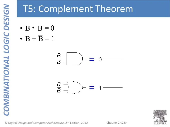
B B = 0
B + B = 1
T5: Complement Theorem
B B = 0
B + B = 1
T5: Complement Theorem
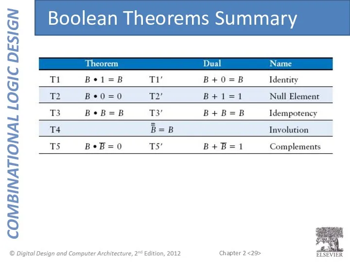
Boolean Theorems Summary
Boolean Theorems Summary
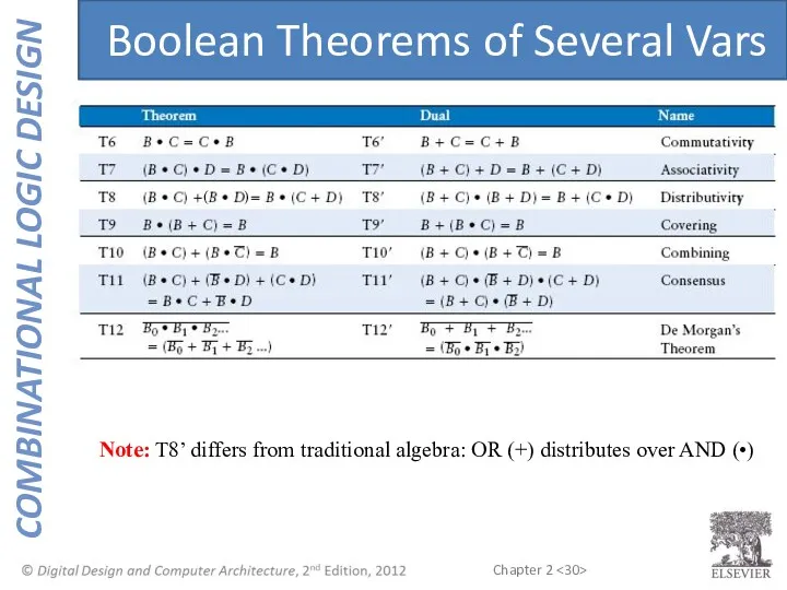
Boolean Theorems of Several Vars
Note: T8’ differs from traditional algebra: OR
Boolean Theorems of Several Vars
Note: T8’ differs from traditional algebra: OR
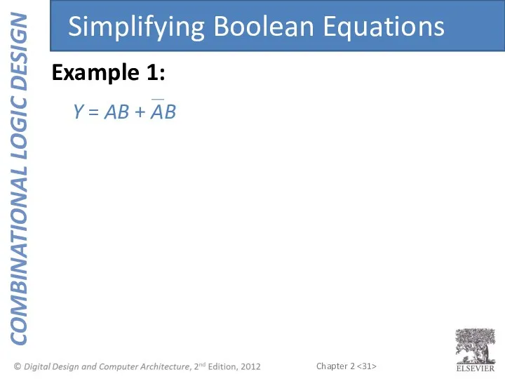
Y = AB + AB
Simplifying Boolean Equations
Example 1:
Y = AB + AB
Simplifying Boolean Equations
Example 1:
Y = AB + AB
= B(A + A) T8
= B(1) T5’
Y = AB + AB
= B(A + A) T8
= B(1) T5’
Y = A(AB + ABC)
Example 2:
Simplifying Boolean Equations
Y = A(AB + ABC)
Example 2:
Simplifying Boolean Equations
Y = A(AB + ABC)
= A(AB(1 + C)) T8
= A(AB(1)) T2’
Y = A(AB + ABC)
= A(AB(1 + C)) T8
= A(AB(1)) T2’
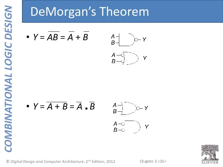
Y = AB = A + B
Y = A + B
Y = AB = A + B
Y = A + B
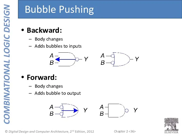
Backward:
Body changes
Adds bubbles to inputs
Forward:
Body changes
Adds bubble to output
Bubble Pushing
Backward:
Body changes
Adds bubbles to inputs
Forward:
Body changes
Adds bubble to output
Bubble Pushing
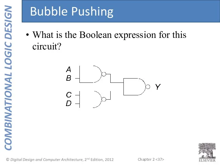
What is the Boolean expression for this circuit?
Bubble Pushing
What is the Boolean expression for this circuit?
Bubble Pushing
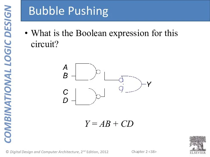
What is the Boolean expression for this circuit?
Y = AB +
What is the Boolean expression for this circuit?
Y = AB +
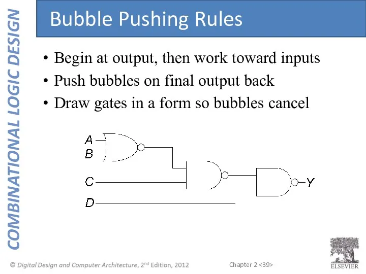
Begin at output, then work toward inputs
Push bubbles on final output
Begin at output, then work toward inputs
Push bubbles on final output
Bubble Pushing Example
Bubble Pushing Example
Bubble Pushing Example
Bubble Pushing Example
Bubble Pushing Example
Bubble Pushing Example
Bubble Pushing Example
Bubble Pushing Example
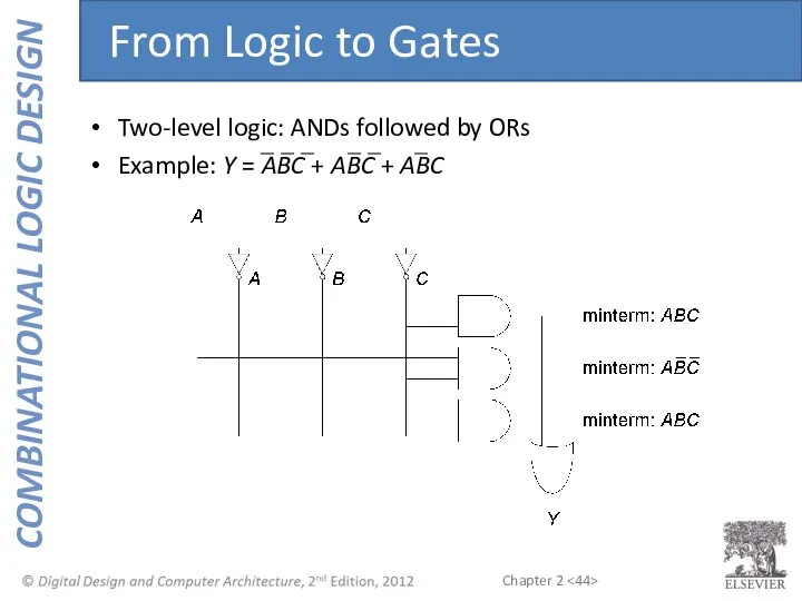
Two-level logic: ANDs followed by ORs
Example: Y = ABC + ABC
Two-level logic: ANDs followed by ORs
Example: Y = ABC + ABC
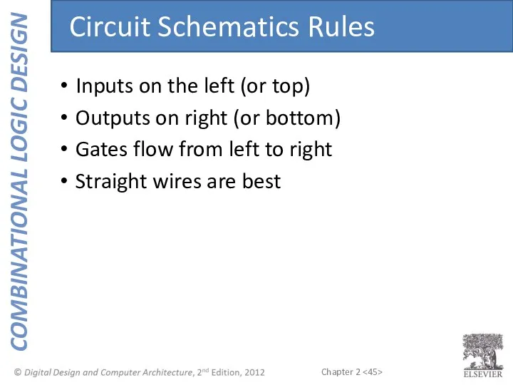
Inputs on the left (or top)
Outputs on right (or bottom)
Gates flow
Inputs on the left (or top)
Outputs on right (or bottom)
Gates flow
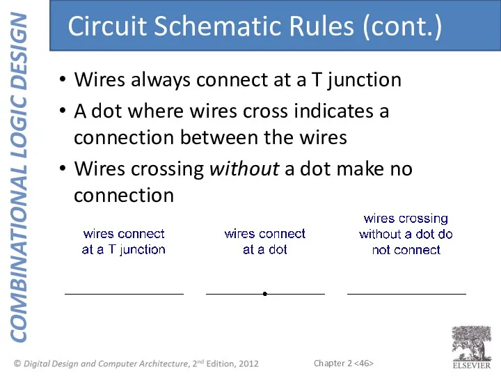
Wires always connect at a T junction
A dot where wires cross
Wires always connect at a T junction
A dot where wires cross
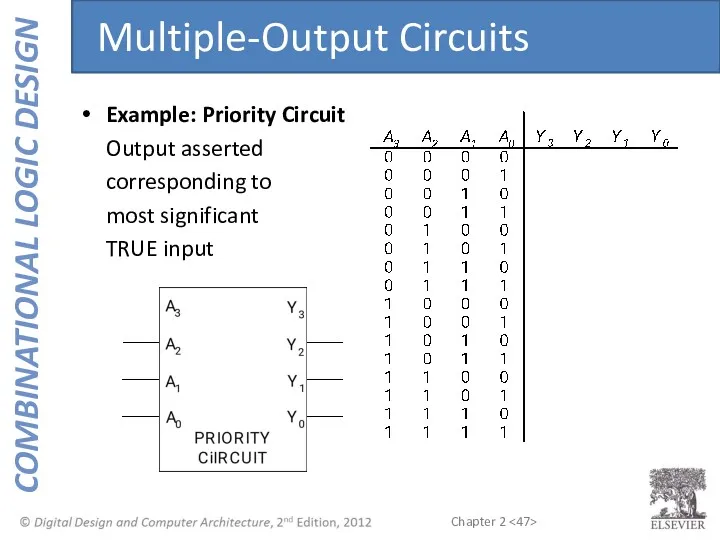
Example: Priority Circuit
Output asserted
corresponding to
most significant
TRUE input
Multiple-Output Circuits
Example: Priority Circuit
Output asserted
corresponding to
most significant
TRUE input
Multiple-Output Circuits
Example: Priority Circuit
Output asserted
corresponding to
most significant
TRUE input
Multiple-Output Circuits
Example: Priority Circuit
Output asserted
corresponding to
most significant
TRUE input
Multiple-Output Circuits
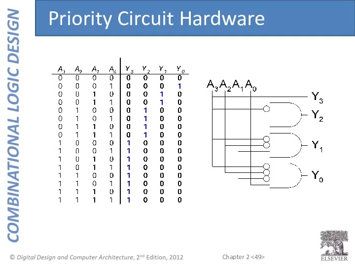
Priority Circuit Hardware
Priority Circuit Hardware
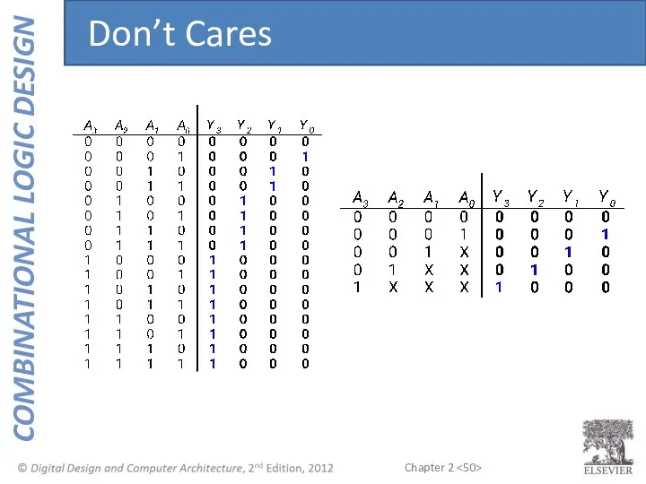
Don’t Cares
Don’t Cares
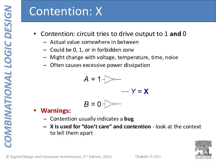
Contention: circuit tries to drive output to 1 and 0
Actual value
Contention: circuit tries to drive output to 1 and 0
Actual value
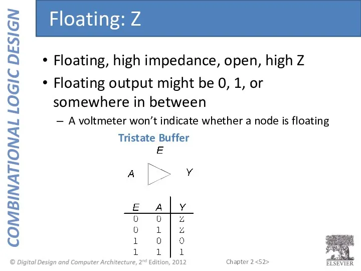
Floating, high impedance, open, high Z
Floating output might be 0, 1,
Floating, high impedance, open, high Z
Floating output might be 0, 1,
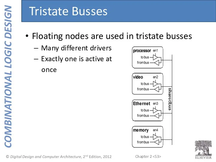
Floating nodes are used in tristate busses
Many different drivers
Exactly one is
Floating nodes are used in tristate busses
Many different drivers
Exactly one is
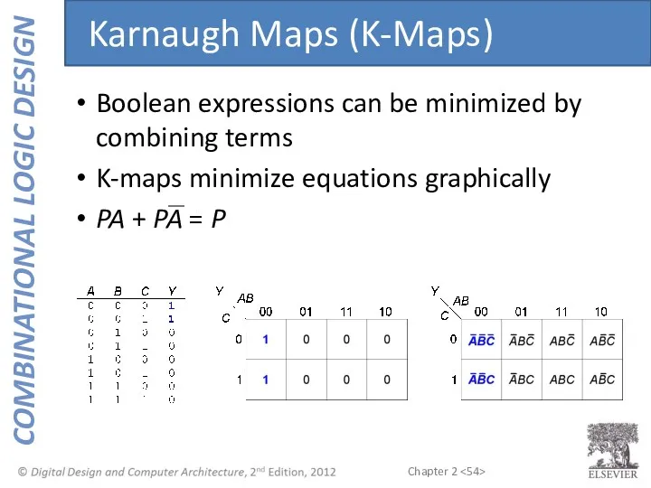
Boolean expressions can be minimized by combining terms
K-maps minimize equations graphically
PA
Boolean expressions can be minimized by combining terms
K-maps minimize equations graphically
PA
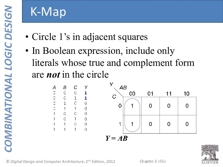
Circle 1’s in adjacent squares
In Boolean expression, include only literals whose
Circle 1’s in adjacent squares
In Boolean expression, include only literals whose
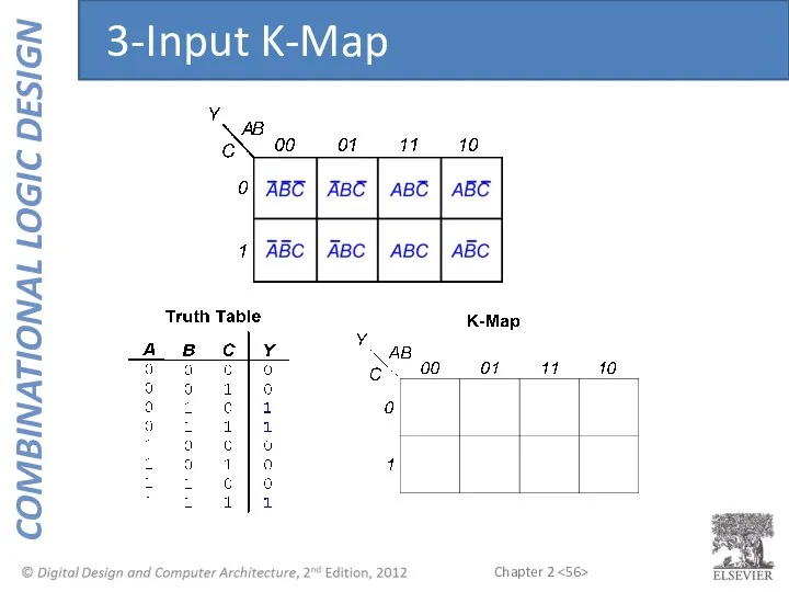
3-Input K-Map
3-Input K-Map
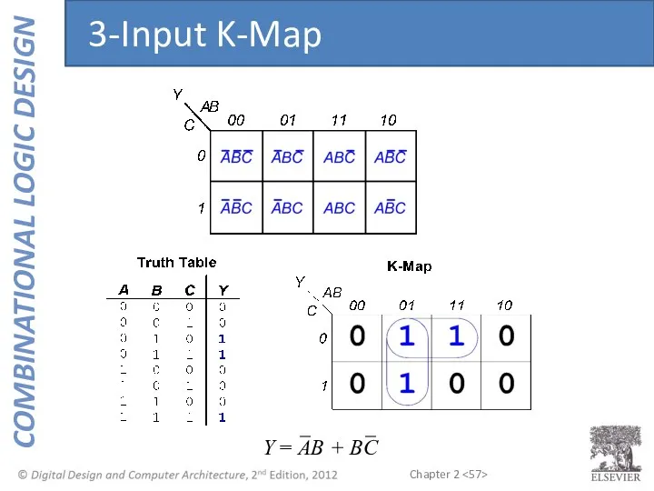
Y = AB + BC
3-Input K-Map
Y = AB + BC
3-Input K-Map
Complement: variable with a bar over it
A, B, C
Literal: variable
Complement: variable with a bar over it
A, B, C
Literal: variable
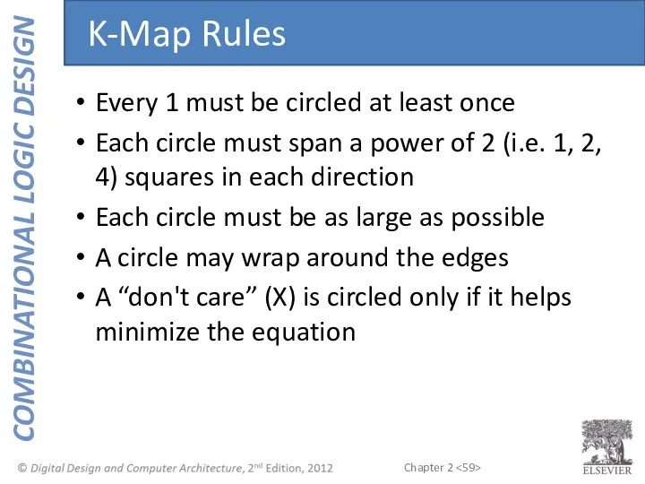
Every 1 must be circled at least once
Each circle must span
Every 1 must be circled at least once
Each circle must span
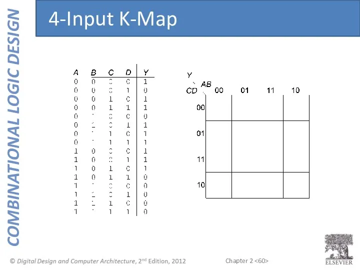
4-Input K-Map
4-Input K-Map
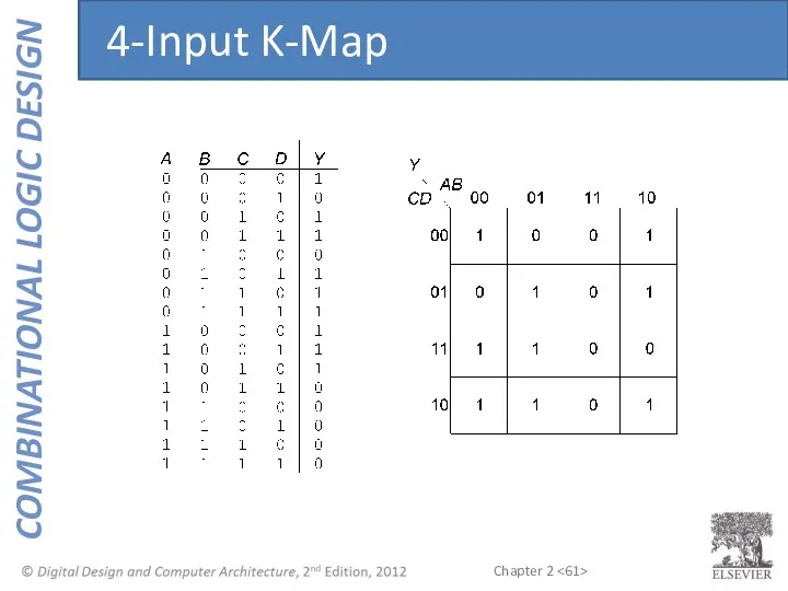
4-Input K-Map
4-Input K-Map
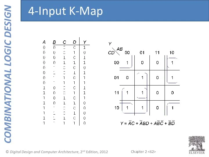
4-Input K-Map
4-Input K-Map
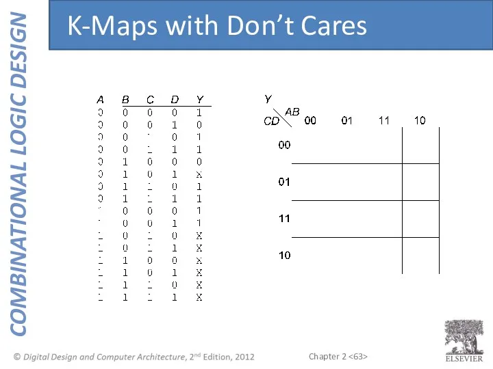
K-Maps with Don’t Cares
K-Maps with Don’t Cares
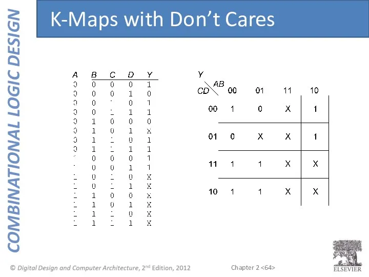
K-Maps with Don’t Cares
K-Maps with Don’t Cares
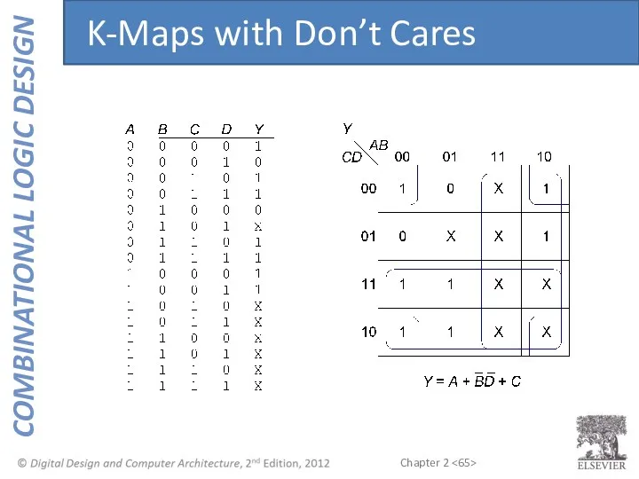
K-Maps with Don’t Cares
K-Maps with Don’t Cares
Multiplexers
Decoders
Combinational Building Blocks
Multiplexers
Decoders
Combinational Building Blocks
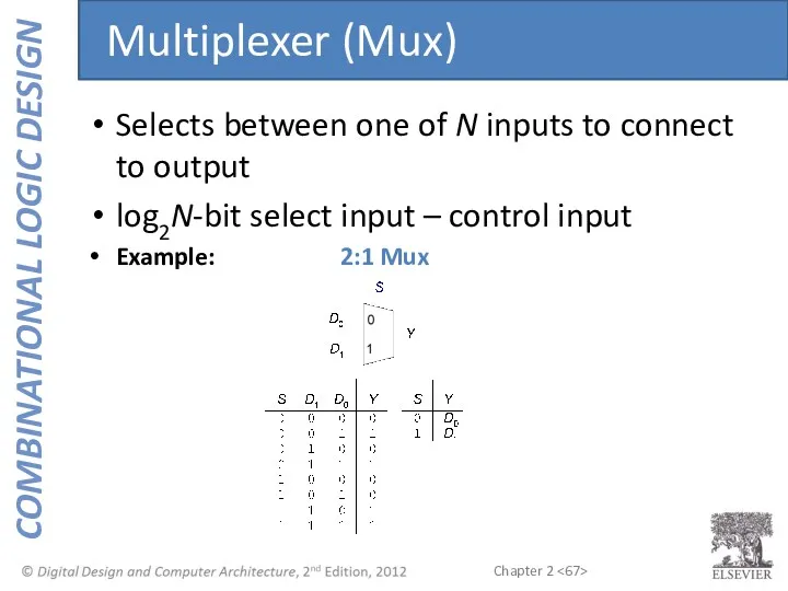
Selects between one of N inputs to connect to output
log2N-bit select
Selects between one of N inputs to connect to output
log2N-bit select
2-<>
Logic gates
Sum-of-products form
Tristates
For an N-input mux, use N tristates
Turn on exactly
2-<>
Logic gates
Sum-of-products form
Tristates
For an N-input mux, use N tristates
Turn on exactly
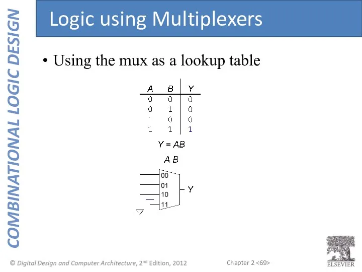
Using the mux as a lookup table
Logic using Multiplexers
Using the mux as a lookup table
Logic using Multiplexers
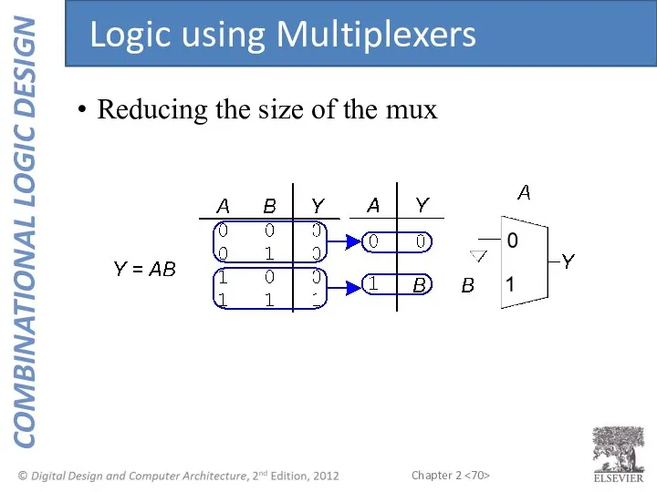
Reducing the size of the mux
Logic using Multiplexers
Reducing the size of the mux
Logic using Multiplexers
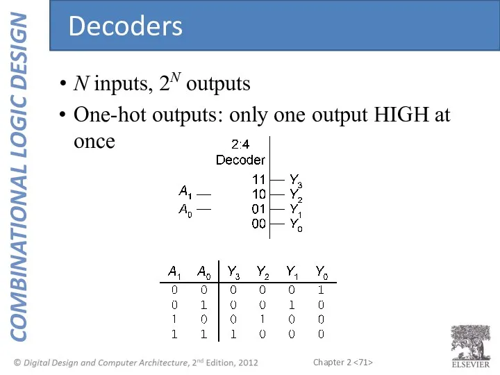
N inputs, 2N outputs
One-hot outputs: only one output HIGH at once
Decoders
N inputs, 2N outputs
One-hot outputs: only one output HIGH at once
Decoders
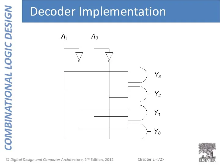
Decoder Implementation
Decoder Implementation
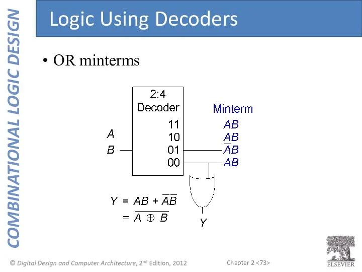
OR minterms
Logic Using Decoders
OR minterms
Logic Using Decoders

ENOUGH FOR TODAY!
ENOUGH FOR TODAY!
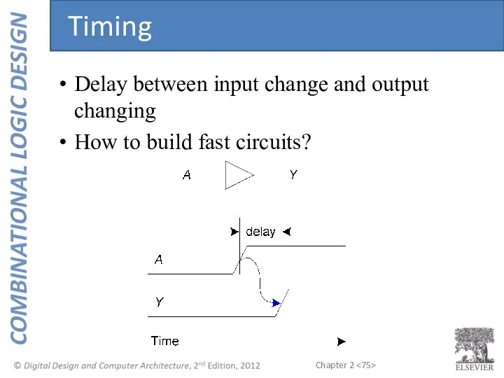
Delay between input change and output changing
How to build fast circuits?
Timing
Delay between input change and output changing
How to build fast circuits?
Timing
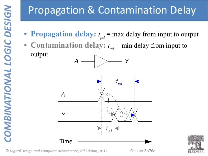
Propagation delay: tpd = max delay from input to output
Contamination delay:
Propagation delay: tpd = max delay from input to output
Contamination delay:
Delay is caused by
Capacitance and resistance in a circuit
Speed of light
Delay is caused by
Capacitance and resistance in a circuit
Speed of light
Critical (Long) Path: tpd = 2tpd_AND + tpd_OR
Short Path: tcd
Critical (Long) Path: tpd = 2tpd_AND + tpd_OR
Short Path: tcd
When a single input change causes an output to change multiple
When a single input change causes an output to change multiple
What happens when A = 0, C = 1, B falls?
Glitch
What happens when A = 0, C = 1, B falls?
Glitch
Glitch Example (cont.)
Glitch Example (cont.)
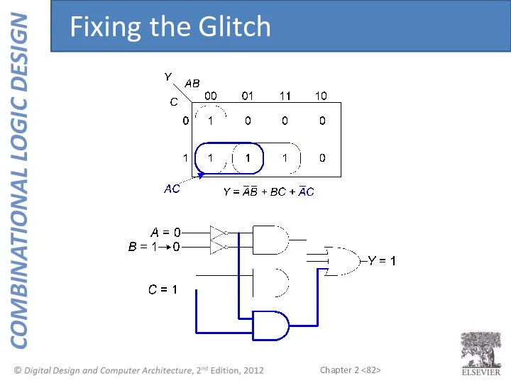
Fixing the Glitch
Fixing the Glitch
 Случаи вычитания 17 -, 18 -
 Descriptive statistics
 Правильные и неправильные дроби. Понятия
 Основное свойство дроби
 Презентация: Деление многозначного числа с нулём на конце делимого(и остатком).
 Презентация Как люди научились считать Диск
 Теоремы об углах, образованных двумя параллельными прямыми и секущей
 Формула площади прямоугольника и квадрата
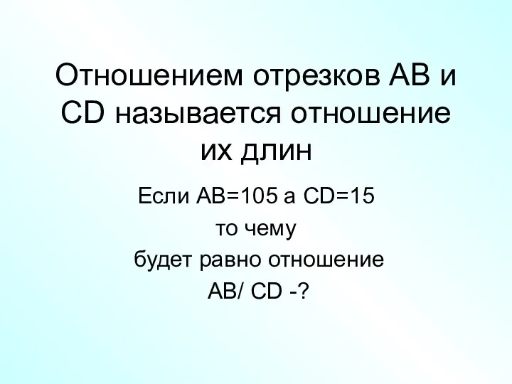 Отношением отрезков AB и CD называется отношение их длин
 Решение неравенств методом интервалов
 Основы финансовой математики
 Решение геометрических задач ГИА №26
 Углы и многоугольники (5 класс)
 Межпредметные связи в математике. Подготовка к ЕГЭ
 Правильные и неправильные дроби
 Два замечательных предела
 Додавання та віднімання дробів з різними знаменниками
 Презентация Геометрические фигуры
 Задания от Буратино (Математика, 1 класс)
 Урок математики в 4 классе Решение задач. Когда количество одинаковое ПНШ
 Слагаемые и сумма
 Презентация к уроку математики. 1 класс. Сантиметр. УМК Школа России
 Случайные погрешности и законы распределения
 Загадки пирамид
 Переместительное свойство умножения
 Вектор - любой направленный отрезок
 Извлечение квадратных корней из больших чисел без калькулятора
 Аксиомы стереометрии. Параллельность в пространстве