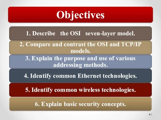
- Designing & Deploying Network Solutions for Small and Medium Busines

Содержание
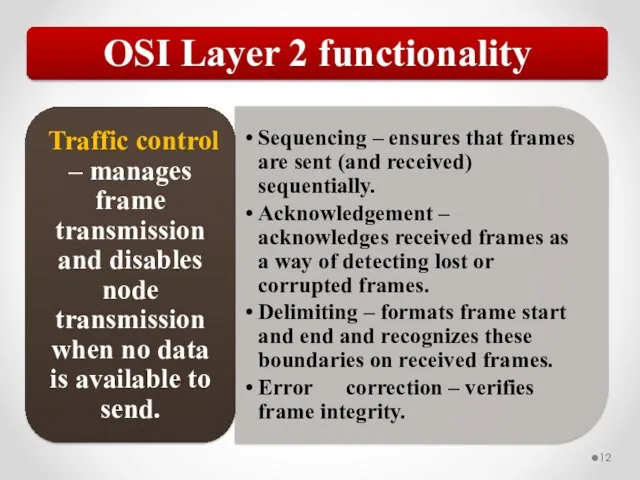
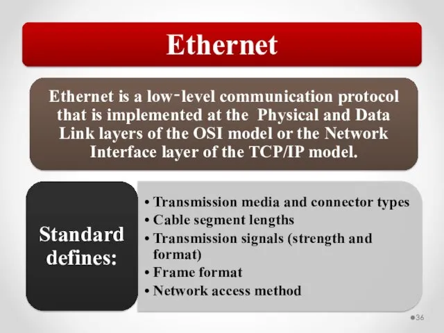
- 45. CSMA/CD Shared media Ethernet uses a network access method known as CSMA/CD. With CSMA/CD, a host
- 46. When a collision occurs: All involved hosts will stop transmitting. Both frames are discarded. Both stations
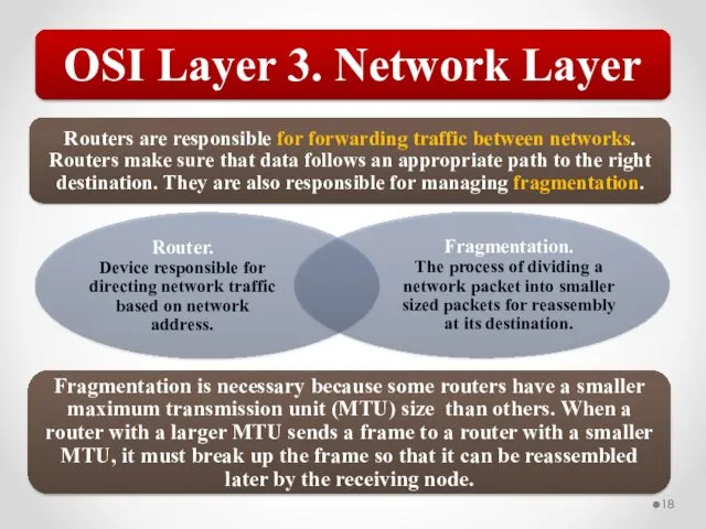
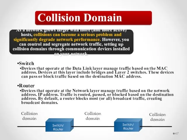
- 47. Collision Domain As a network grows larger with more (and more active) hosts, collisions can become
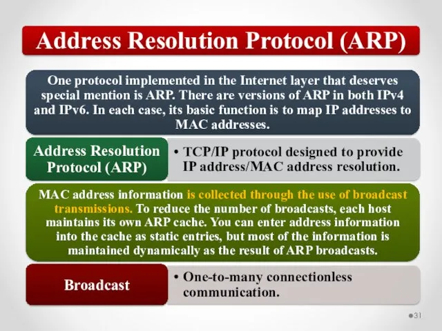
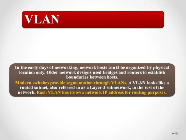
- 48. VLAN In the early days of networking, network hosts could be organized by physical location only.
- 49. VLAN The simplest type of VLAN is a static VLAN. In this configuration, switch ports are
- 50. VLAN and Ethernet When using VLANs on an Ethernet network, each frame includes an 802.1Q tag
- 51. Defined by 802.11 standards. Standards in the 802.11 family define a through-the-air interface between a wireless
- 52. Current Wireless Standards 802.11g is downward compatible with 802.11b 802.11n is downward compatible with 802.11a, 802.11b,
- 53. CSMA/CA The network access method used by 802.11 wireless is CSMA/CA (Carrier Sense Multiple Access with
- 54. Authentication and resource access Data and communication security Security Basics
- 55. What you know Password or PIN What you have Smart card, ID badge, etc. Who you
- 56. Prevent data from being exposed Prevent data from being corrupted Data Security The use of data
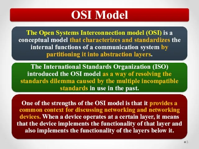
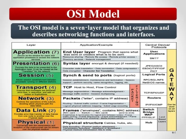
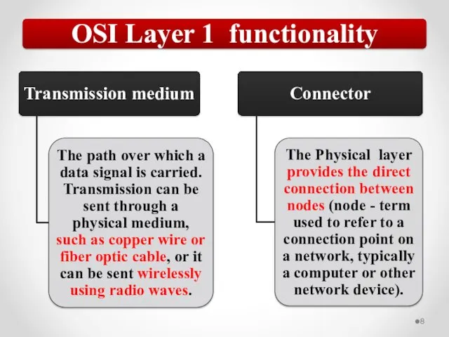
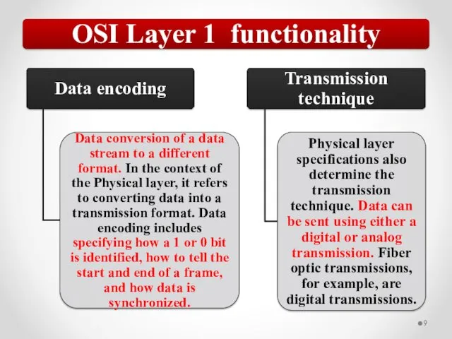
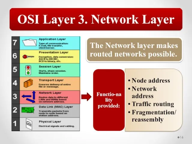
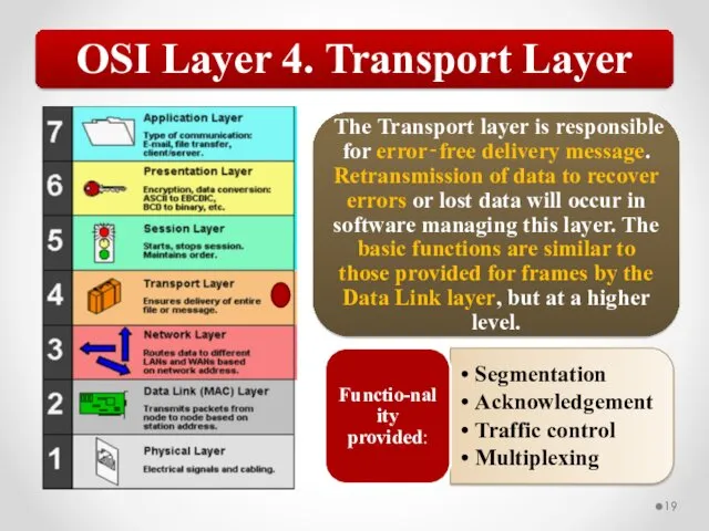
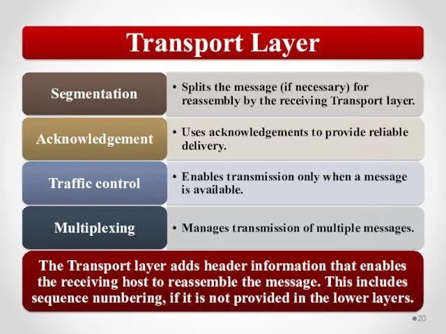
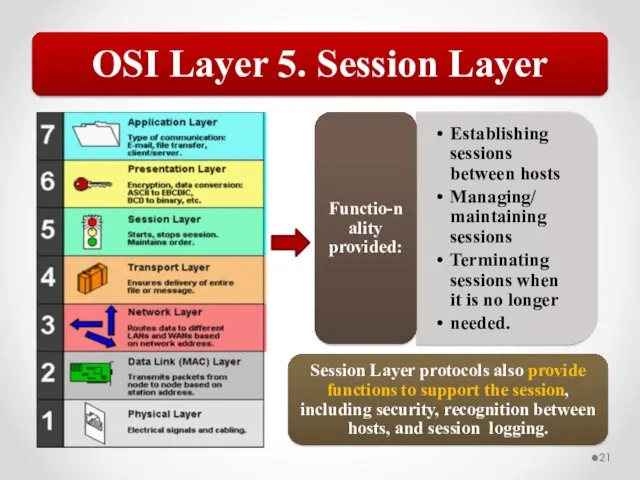
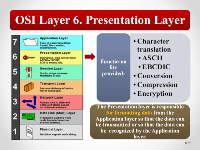
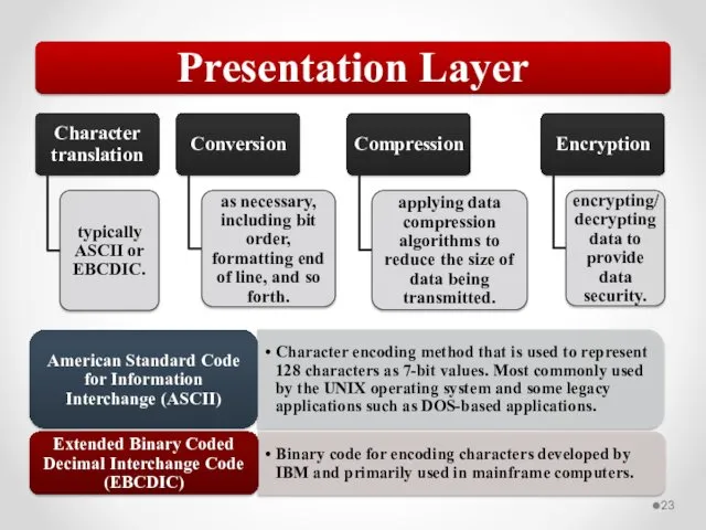
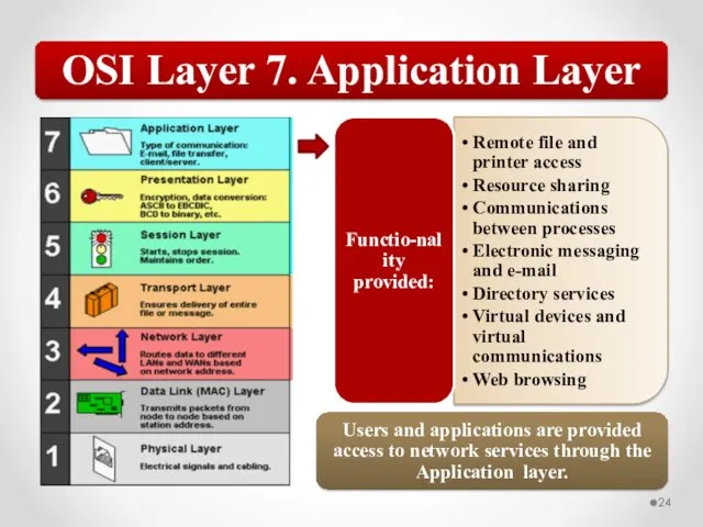
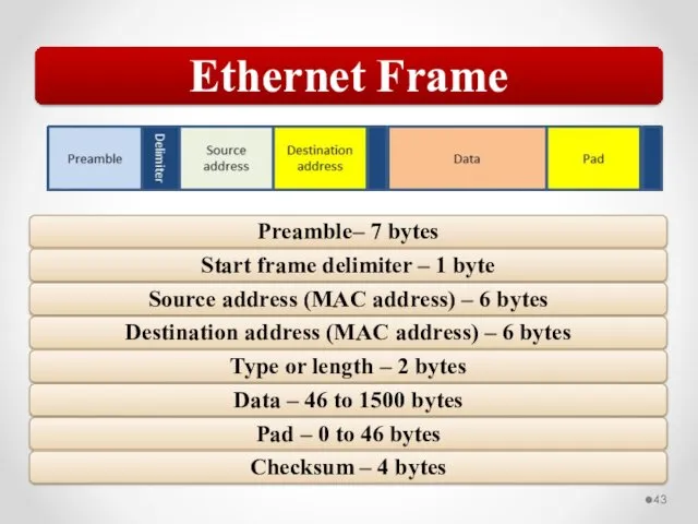
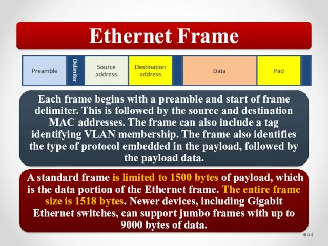
- 57. The OSI model describes network functions as seven distinct layers. Layer 1, the Physical layer, is
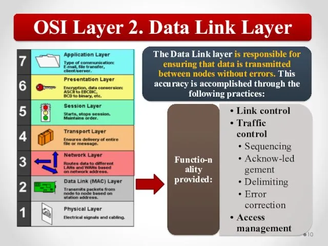
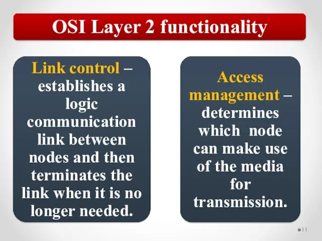
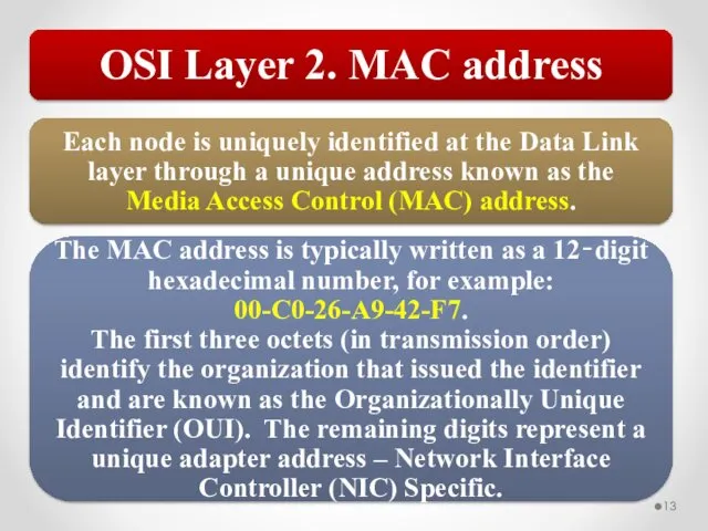
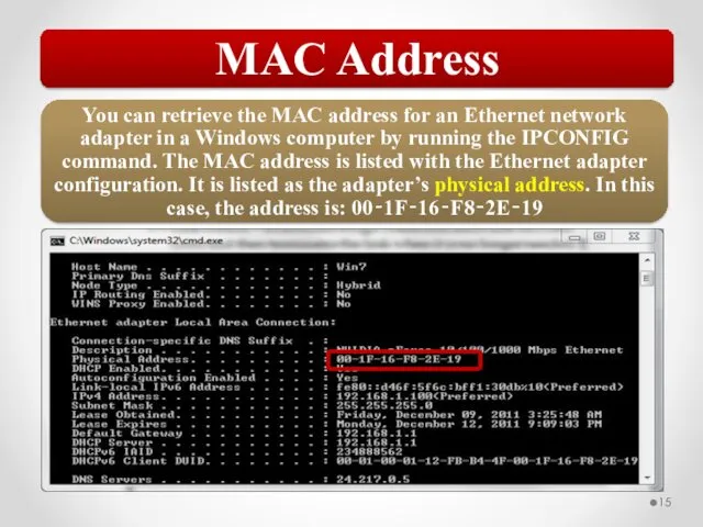
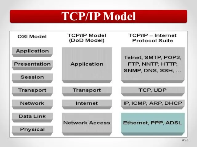
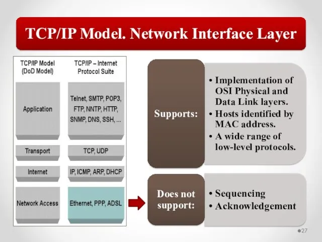
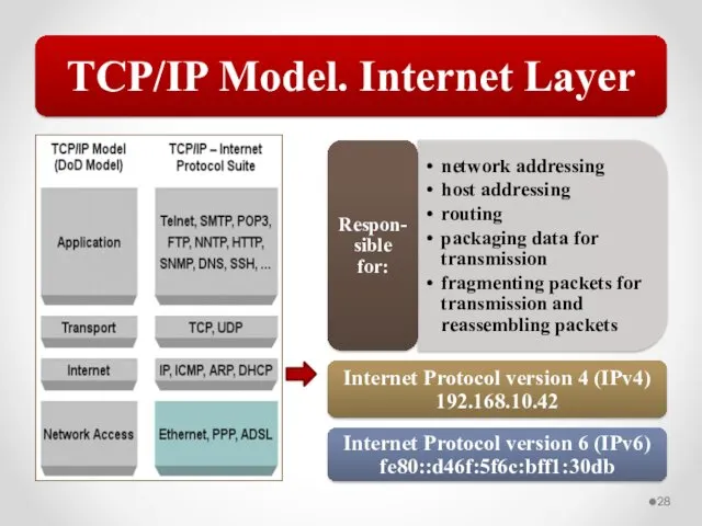
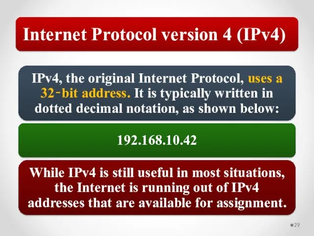
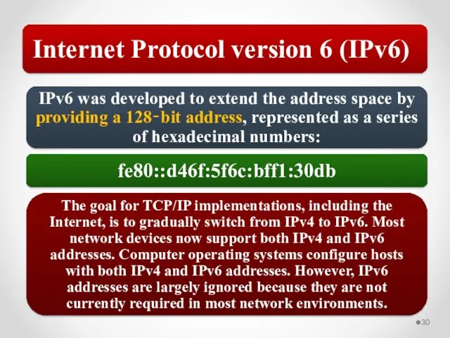
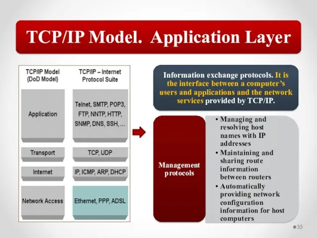
- 58. The MAC address is implemented at Layer 2 and uniquely identifies a network host. The TCP/IP
- 59. Network traffic can be a mix of unicast, broadcast, multicast, and anycast traffic. 802.3 uses CSMA/CD
- 61. Скачать презентацию


CSMA/CD
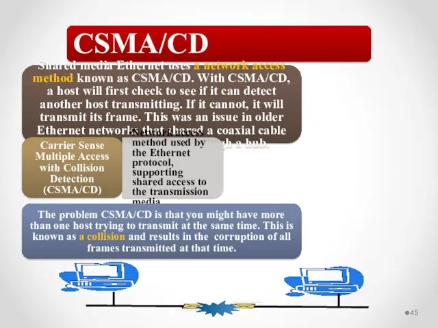
Shared media Ethernet uses a network access method known as CSMA/CD.
CSMA/CD
Shared media Ethernet uses a network access method known as CSMA/CD.
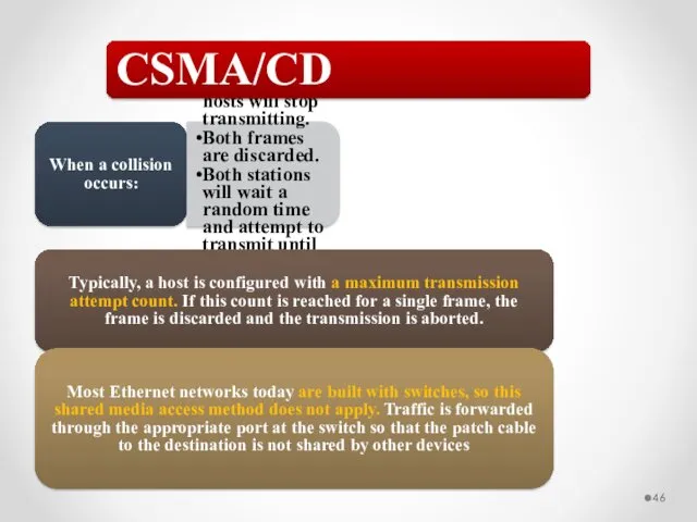
When a collision occurs:
All involved hosts will stop transmitting.
Both frames are
When a collision occurs:
All involved hosts will stop transmitting.
Both frames are
Collision Domain
As a network grows larger with more (and more active)
Collision Domain
As a network grows larger with more (and more active)
VLAN
In the early days of networking, network hosts could be organized
VLAN
In the early days of networking, network hosts could be organized

VLAN
The simplest type of VLAN is a static VLAN. In this
VLAN
The simplest type of VLAN is a static VLAN. In this
VLAN and Ethernet
When using VLANs on an Ethernet network, each
VLAN and Ethernet
When using VLANs on an Ethernet network, each
Defined by 802.11 standards. Standards in the 802.11 family define a
Defined by 802.11 standards. Standards in the 802.11 family define a
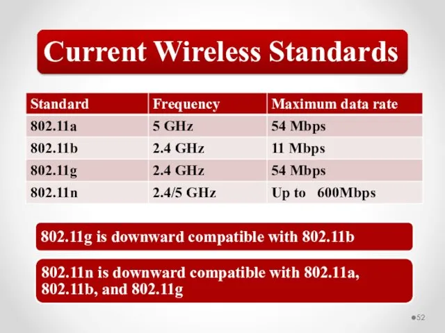
Current Wireless Standards
802.11g is downward compatible with 802.11b
802.11n is downward compatible
Current Wireless Standards
802.11g is downward compatible with 802.11b
802.11n is downward compatible
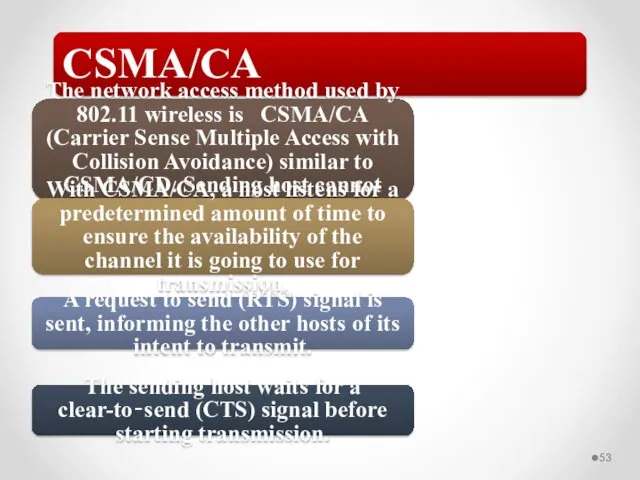
CSMA/CA
The network access method used by 802.11 wireless is CSMA/CA (Carrier
CSMA/CA
The network access method used by 802.11 wireless is CSMA/CA (Carrier
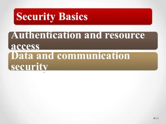
Authentication and resource access
Data and communication security
Security Basics
Authentication and resource access
Data and communication security
Security Basics
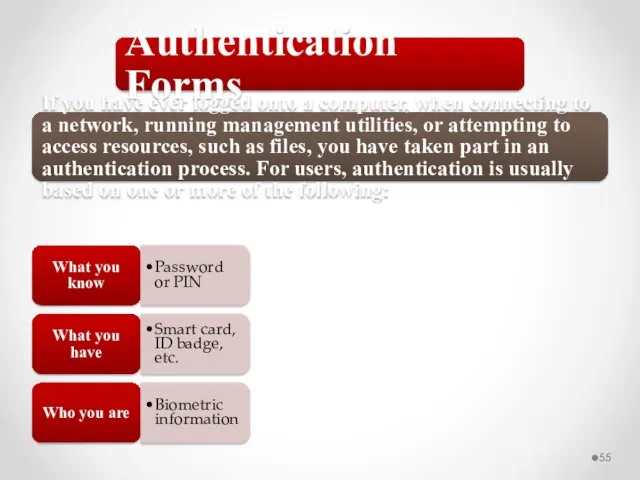
What you know
Password or PIN
What you have
Smart card, ID badge, etc.
Who
What you know
Password or PIN
What you have
Smart card, ID badge, etc.
Who
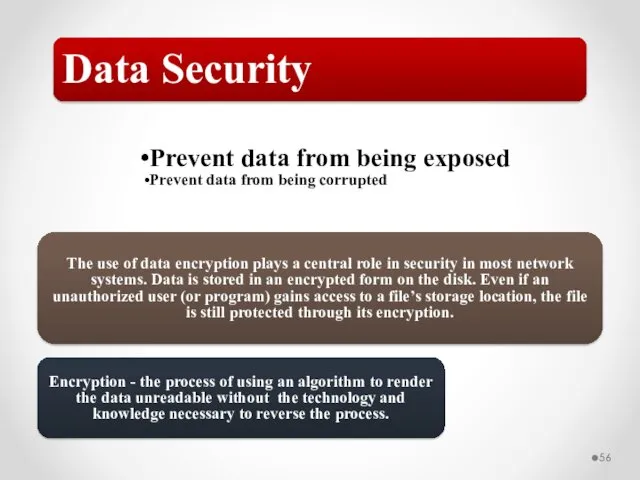
Prevent data from being exposed
Prevent data from being corrupted
Data Security
The use
Prevent data from being exposed
Prevent data from being corrupted
Data Security
The use
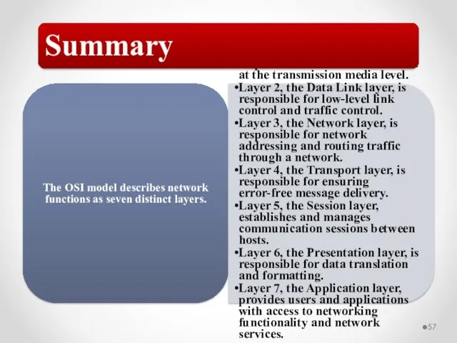
The OSI model describes network functions as seven distinct layers.
Layer 1,
The OSI model describes network functions as seven distinct layers.
Layer 1,
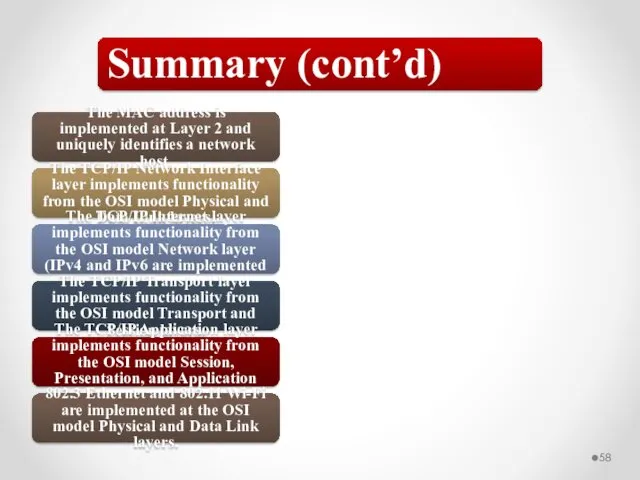
The MAC address is implemented at Layer 2 and uniquely identifies
The MAC address is implemented at Layer 2 and uniquely identifies
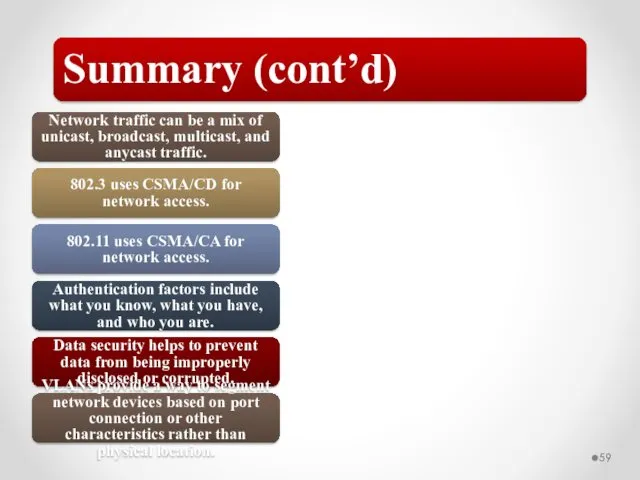
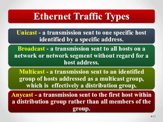
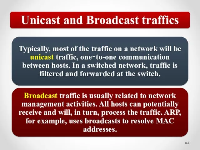
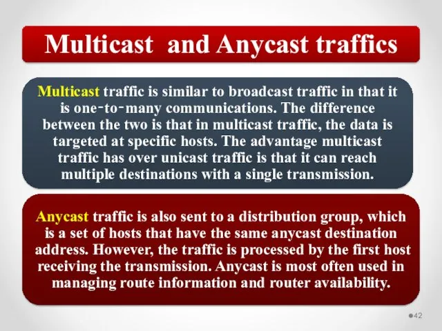
Network traffic can be a mix of unicast, broadcast, multicast, and
Network traffic can be a mix of unicast, broadcast, multicast, and
 Профессиональная этика и деловой этикет
 Статистический контроль качества в СМК
 Организационная культура в системе управления. Лекция 2
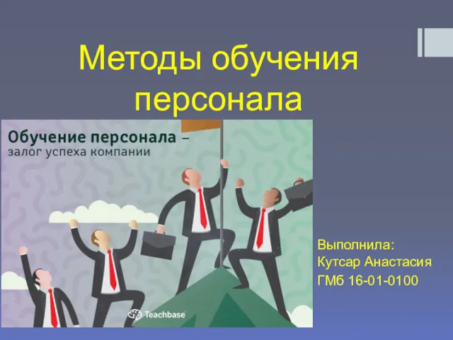 Методы обучения персонала
 История развития проектного управления
 Работа с возражениями
 Формирование кадровой политики организации
 Формы организации производства
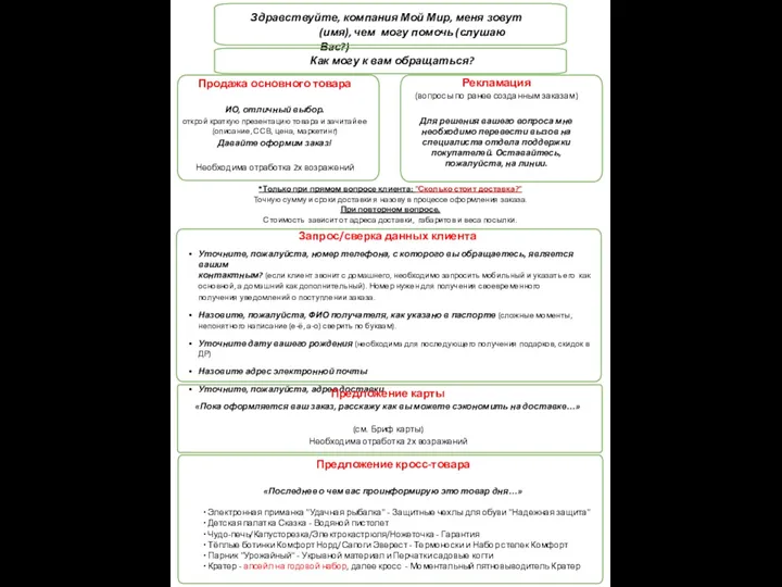 Компания Мой мир
 Функции управления проектом
 Понятие, цели и задачи управления инфраструктурой предприятия. (Лекция 1)
 Отличие команд от рабочих групп. Выращивание команд. Жизненный цикл команды. (Тема 8)
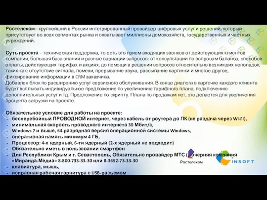 Ростелеком. Техническая поддержка
 ГОСТ Р 57189-2016/ISO/TS 9002:2016. Системы менеджмента качества. Руководство по применению ИСО 9001:2015
 Разработка технологии и расширение ассортимента блюд и напитков в ресторане с национальной кухней на 280 посадочных мест
 Теория жизненных циклов организации
 Ділові папери як засіб писемної професійної комунікації
 Методы исследований в управлении изменениями в организации
 Выпускная квалификационная работа: Повышения эффективности организационно-экономического выбора поставщиков
 Организационная структура управления
 Добування й обробка документів міжнародної інформації
 Планирование потребности в персонале
 Команда гребцов ГП
 Модели мониторинга качества образования
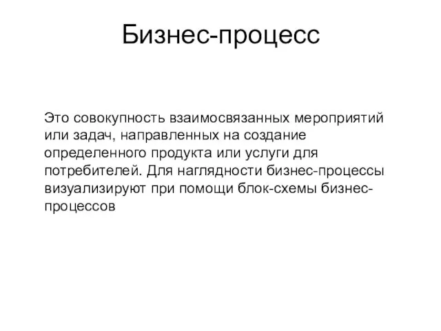 Виды бизнес-процессов. Управление бизнес-процессами
 Объекты и субъекты сферы услуг
 Управленческие решения
 Системы управления качеством. Лекция 3