- Adjustment procedure compressor control block

Содержание
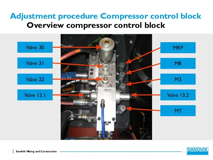
- 2. Adjustment procedure Compressor control block Overview compressor control block Valve 13.1 Valve 22 Valve 31 Valve
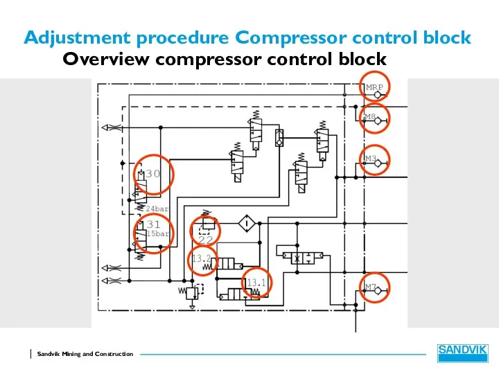
- 3. Adjustment procedure Compressor control block Overview compressor control block
- 4. Adjustment procedure Compressor control block The compressor control block normally comes already adjusted but in case
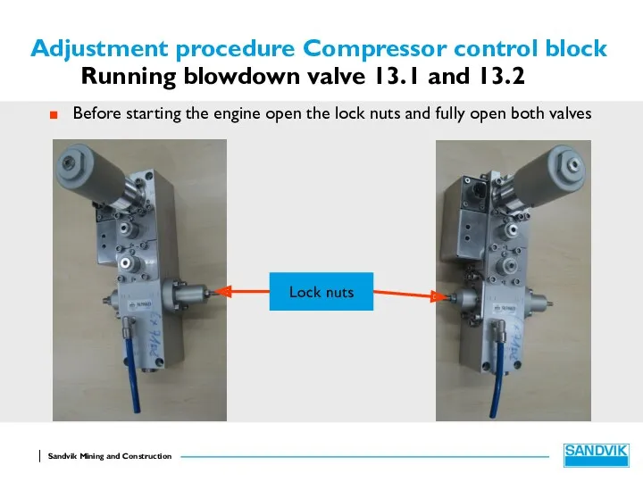
- 5. Adjustment procedure Compressor control block Running blowdown valve 13.1 and 13.2 Before starting the engine open
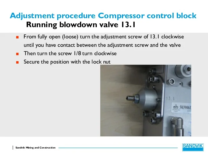
- 6. Adjustment procedure Compressor control block Running blowdown valve 13.1 From fully open (loose) turn the adjustment
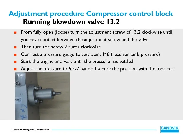
- 7. Adjustment procedure Compressor control block Running blowdown valve 13.2 From fully open (loose) turn the adjustment
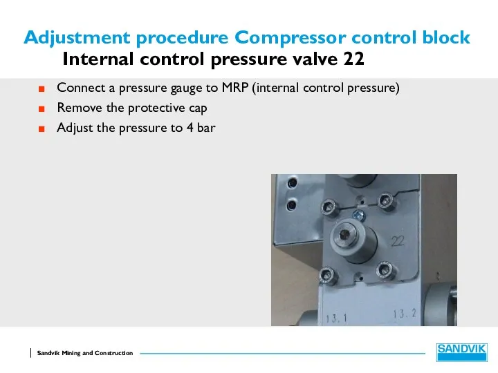
- 8. Adjustment procedure Compressor control block Internal control pressure valve 22 Connect a pressure gauge to MRP
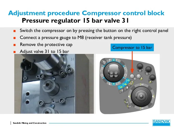
- 9. Adjustment procedure Compressor control block Pressure regulator 15 bar valve 31 Switch the compressor on by
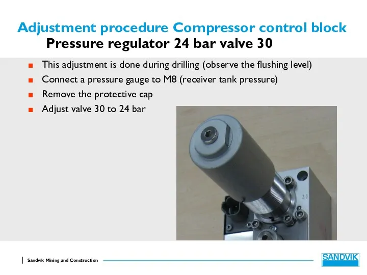
- 10. Adjustment procedure Compressor control block Pressure regulator 24 bar valve 30 This adjustment is done during
- 11. Adjustment procedure Compressor control block Pressure regulator 24 bar valve 30 A special tool is available
- 12. Adjustment procedure Compressor control block Drilling with different size hammers
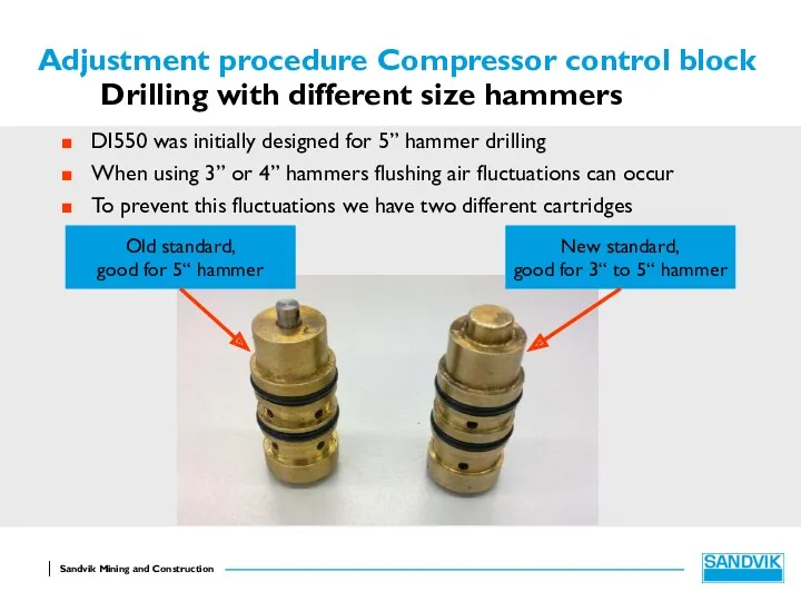
- 13. Adjustment procedure Compressor control block Drilling with different size hammers DI550 was initially designed for 5”
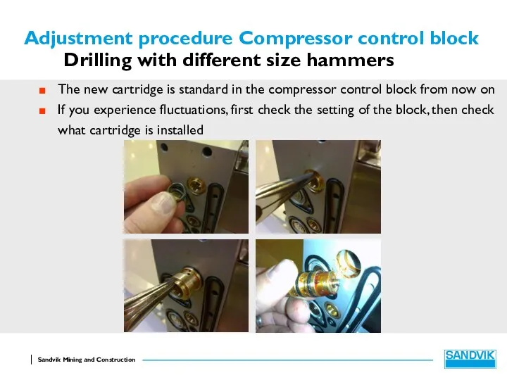
- 14. Adjustment procedure Compressor control block Drilling with different size hammers The new cartridge is standard in
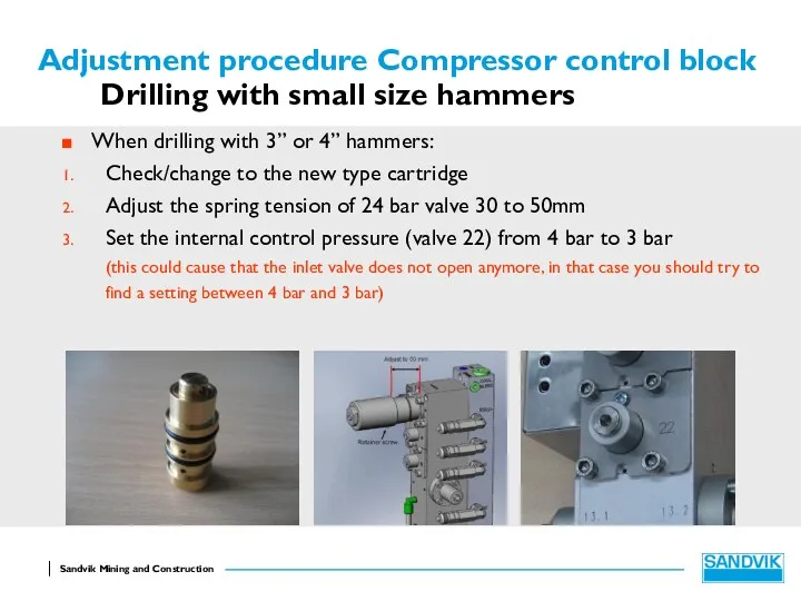
- 15. Adjustment procedure Compressor control block Drilling with small size hammers When drilling with 3” or 4”
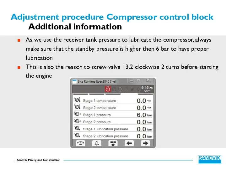
- 16. Adjustment procedure Compressor control block Additional information As we use the receiver tank pressure to lubricate
- 18. Скачать презентацию
Adjustment procedure Compressor control block
Overview compressor control block
Valve 13.1
Valve 22
Valve 31
Valve
Adjustment procedure Compressor control block
Overview compressor control block
Valve 13.1
Valve 22
Valve 31
Valve
Adjustment procedure Compressor control block
Overview compressor control block
Adjustment procedure Compressor control block
Overview compressor control block
Adjustment procedure Compressor control block
The compressor control block normally comes already
Adjustment procedure Compressor control block
The compressor control block normally comes already
Adjustment procedure Compressor control block
Running blowdown valve 13.1 and 13.2
Before starting
Adjustment procedure Compressor control block
Running blowdown valve 13.1 and 13.2
Before starting
Adjustment procedure Compressor control block
Running blowdown valve 13.1
From fully open (loose)
Adjustment procedure Compressor control block
Running blowdown valve 13.1
From fully open (loose)
Adjustment procedure Compressor control block
Running blowdown valve 13.2
From fully open (loose)
Adjustment procedure Compressor control block
Running blowdown valve 13.2
From fully open (loose)
Adjustment procedure Compressor control block
Internal control pressure valve 22
Connect a pressure
Adjustment procedure Compressor control block
Internal control pressure valve 22
Connect a pressure
Adjustment procedure Compressor control block
Pressure regulator 15 bar valve 31
Switch the
Adjustment procedure Compressor control block
Pressure regulator 15 bar valve 31
Switch the
Adjustment procedure Compressor control block
Pressure regulator 24 bar valve 30
This adjustment
Adjustment procedure Compressor control block
Pressure regulator 24 bar valve 30
This adjustment
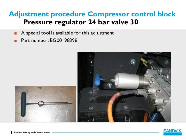
Adjustment procedure Compressor control block
Pressure regulator 24 bar valve 30
A special
Adjustment procedure Compressor control block
Pressure regulator 24 bar valve 30
A special
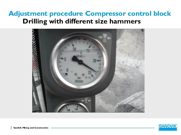
Adjustment procedure Compressor control block
Drilling with different size hammers
Adjustment procedure Compressor control block
Drilling with different size hammers
Adjustment procedure Compressor control block
Drilling with different size hammers
DI550 was initially
Adjustment procedure Compressor control block
Drilling with different size hammers
DI550 was initially
Adjustment procedure Compressor control block
Drilling with different size hammers
The new cartridge
Adjustment procedure Compressor control block
Drilling with different size hammers
The new cartridge
Adjustment procedure Compressor control block
Drilling with small size hammers
When drilling with
Adjustment procedure Compressor control block
Drilling with small size hammers
When drilling with
Adjustment procedure Compressor control block
Additional information
As we use the receiver tank
Adjustment procedure Compressor control block
Additional information
As we use the receiver tank
 Презентация с картинками по пдд
 Йод р-н 5% . Нітроглицерин
 Своя игра. География
 Стратегическое развитие предприятия: выбор и обоснование направлений
 ИППП (хламидиоз)
 Назначение и классификация общесудовых систем. Тема 2.1
 ЭЛОУ-АТ-6 (блок ЭЛОУ). Электродегидратор
 Оригами. Геометрия бумажного листа
 Деловой этикет в Италии
 часть
часть НЕПРЕРЫВНОЕ ПРОФИЛЬНОЕХУДОЖЕСТВЕННО-ЭСТЕТИЧЕСКОЕ ОБРАЗОВАНИЕВ ШКОЛЕ ИСКУССТВ С УГЛУБЛЕННЫМ ИЗУЧЕНИЕМПРЕДМЕТОВ ИСКУССТВА
 Методологические принципы проектирования организационных структур
 Государственные символы России. Конституция РФ
 Лекарственная проблематика лечения метастатических поражений головного мозга
 Подготовка к ЕГЭ по органической химии.
 Обзор книги Брайана Трейси Выйди из зоны комфорта. Измени свою жизнь. 21 метод повышения личной эффективности
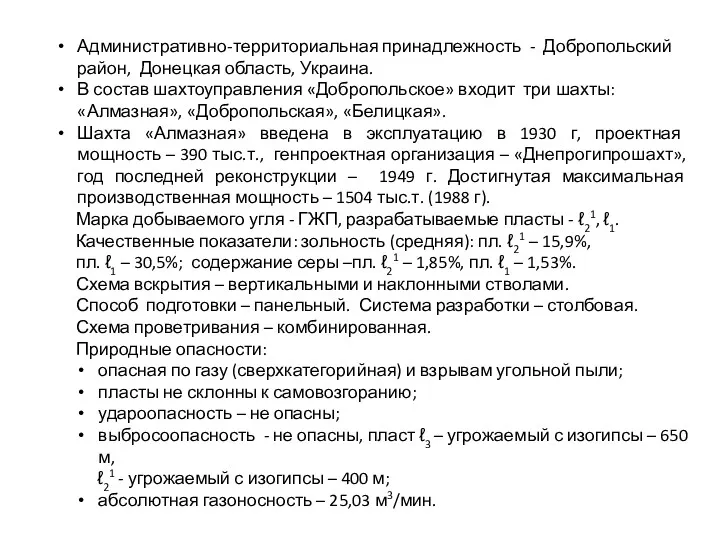 Шахтоуправление Добропольское
 Презентация Образовательные программы в системе дополнительного образования детей
 Синхронный генератор
 История дизайна. Архитектурно-художественное творчество в Советской России
 Народная педагогика конца XIX века
 Стартап - ресторан 100 юаней
 презентация к классному часу Курить - здоровью вредить
 Лечение аномалий окклюзии зубных рядов
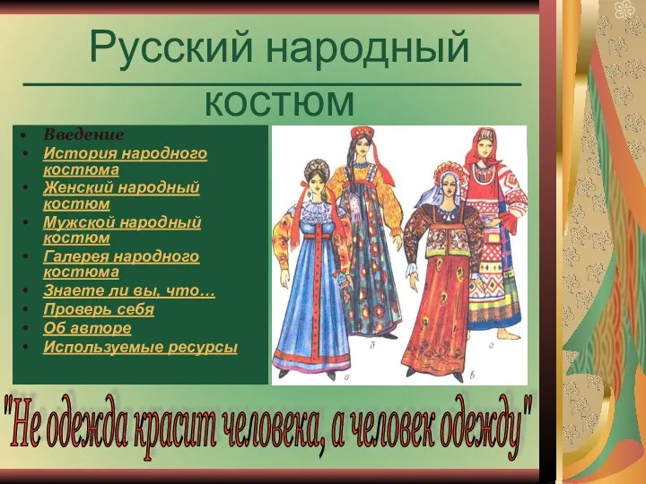 Презентация Русские народные костюмы
 Презентация Основы коррекционной работы по ФФН Диск
 Шаблон игры Учись различать звонкие и глухие согласные звуки
 Акцентуации черт характера