- NV75K5541RS Training Manual

Содержание
- 2. Precaution Feature and Specifications Installation Function Service Information Disassembly and Assembly Trouble shooting Circuit Diagram Wiring
- 3. 1. All repairs should be done in accordance with the procedures described in this manual. This
- 4. 8. Never defeat any of the B+ voltage interlocks. Do not apply AC power to the
- 5. General Specification Dual cook mode Full size inner glass Pop-up dial & Touch glass Large capacity
- 6. 2-1. Features Features and Specifications Concept : Dual cook mode Half Loading 1 Dual Cooking 2
- 7. 2-2. Features Concept : Precise temperature control Always precisely the right cooking temperature for optimal results.
- 8. 2-3. Control Panel Features and Specifications
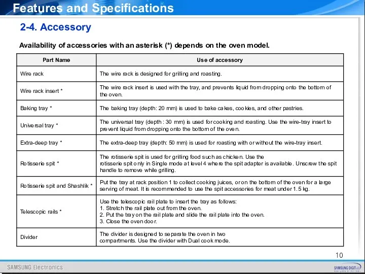
- 9. 2-4. Accessory Availability of accessories with an asterisk (*) depends on the oven model. Features and
- 10. 2-4. Accessory Availability of accessories with an asterisk (*) depends on the oven model. Features and
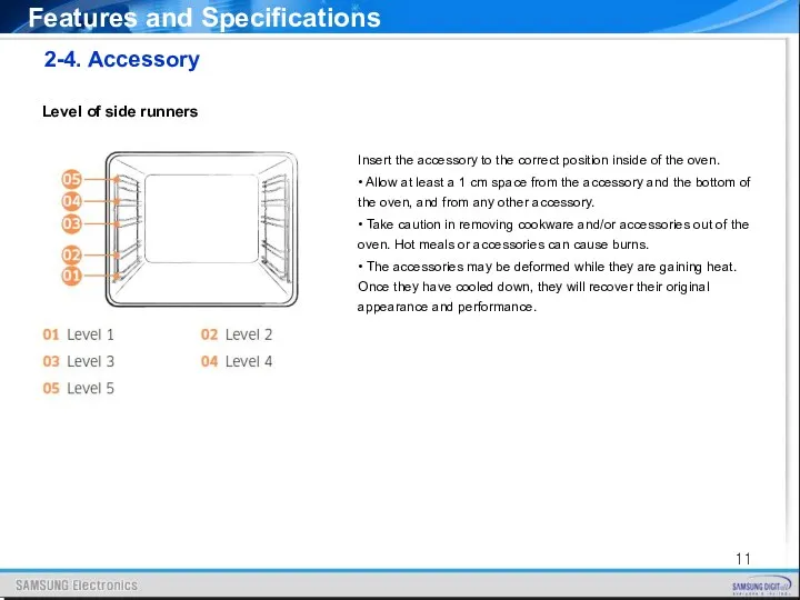
- 11. 2-4. Accessory Level of side runners Insert the accessory to the correct position inside of the
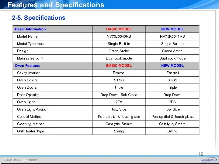
- 12. 2-5. Specifications Features and Specifications
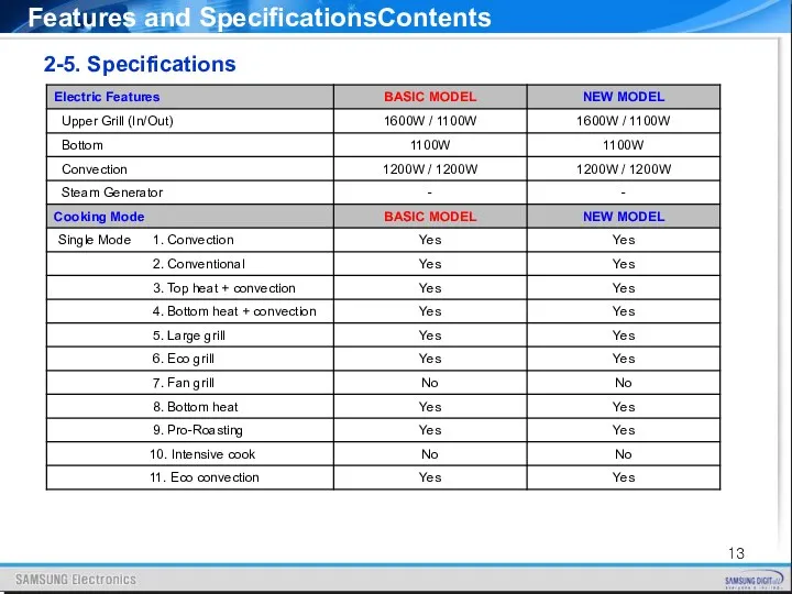
- 13. Features and SpecificationsContents 2-5. Specifications
- 14. Features and SpecificationsContents 2-5. Specifications
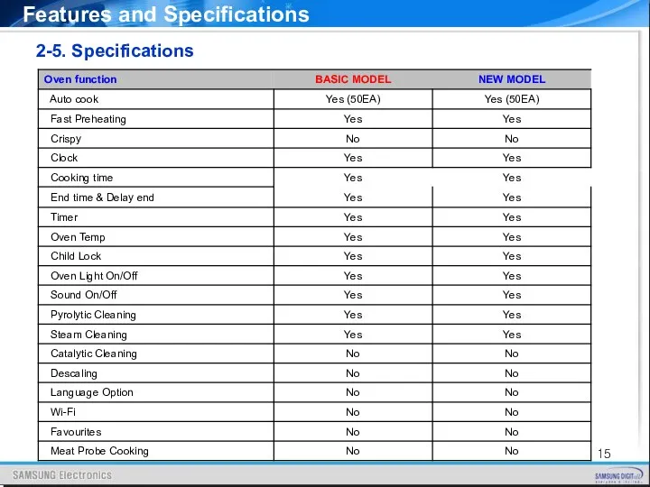
- 15. 2-5. Specifications Features and Specifications
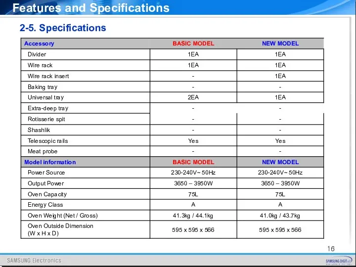
- 16. 2-5. Specifications Features and Specifications
- 17. IMPORTANT Any electrical installation work must be carried out by a qualified electrician / competent person.
- 18. 3-2. The work in the low cabinet Installation
- 19. 3-3. The work in the high cabinet Installation
- 20. 3-4. Caution during installation Installation Secure at least 3 mm of gap in the picture so
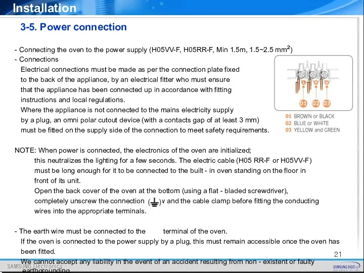
- 21. - Connecting the oven to the power supply (H05VV-F, H05RR-F, Min 1.5m, 1.5~2.5 mm²) - Connections
- 22. 4-1. Cooking Mode Function
- 23. 4-2. Special Function Function
- 24. 4-3. Steam Cleaning Function Steam cleaning is useful for cleaning light soiling with steaming. 1. Pour
- 25. 5-1. Information Codes Service Information Change the current time to 0:00 and press [Timer] and [Back]
- 26. 5-2. Thermo cut-out Two pieces of thermo cut-out are mounted in order to monitor abnormal operation
- 27. 5-3. PCB The operating power of Main PCB performs stable operation at a large range of
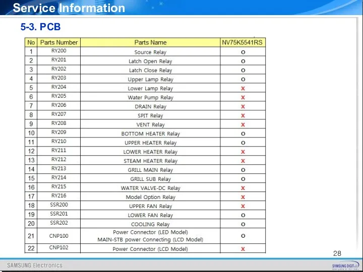
- 28. 5-3. PCB Service Information
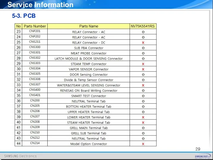
- 29. 5-3. PCB Service Information
- 30. ※ Tools for Removal and reassembly Disassembly and Assembly
- 31. 6 - 1 Replacement of Door Assembly Disassembly and Assembly 1. Open the door and flip
- 32. 6 - 2 Replacement of Door Glass (3Glass) Disassembly and Assembly 1. Use a screwdriver to
- 33. Disassembly and Assembly 6 - 2 Replacement of Door Glass (3Glass) 6. When done, reinsert the
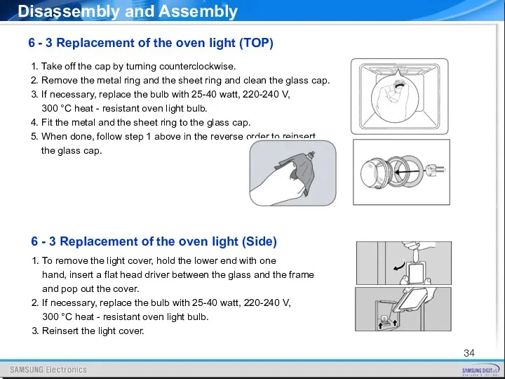
- 34. 1. Take off the cap by turning counterclockwise. 2. Remove the metal ring and the sheet
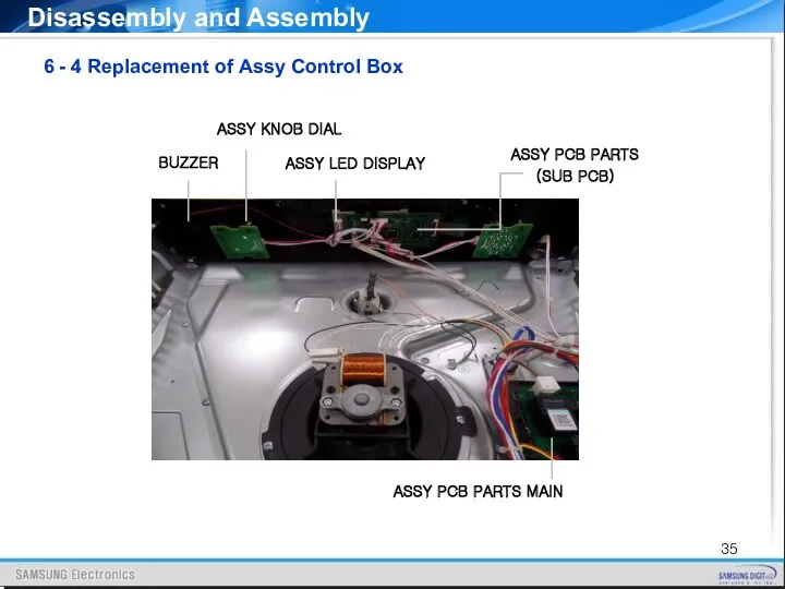
- 35. 6 - 4 Replacement of Assy Control Box Disassembly and Assembly
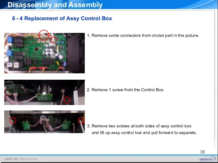
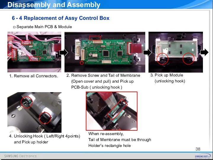
- 36. Disassembly and Assembly 1. Remove some connectors from circled part in the picture. 2. Remove 1
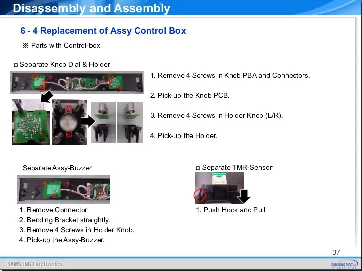
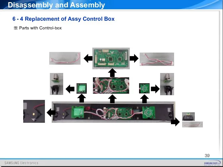
- 37. Disassembly and Assembly ※ Parts with Control-box 6 - 4 Replacement of Assy Control Box 1.
- 38. Disassembly and Assembly 6 - 4 Replacement of Assy Control Box □ Separate Main PCB &
- 39. Disassembly and Assembly ※ Parts with Control-box 6 - 4 Replacement of Assy Control Box
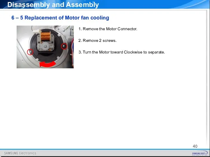
- 40. Disassembly and Assembly 6 – 5 Replacement of Motor fan cooling 1. Remove the Motor Connector.
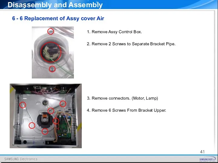
- 41. 6 - 6 Replacement of Assy cover Air Disassembly and Assembly 1. Remove Assy Control Box.
- 42. 1. Remove 5 screws at the back inside cavity to separate the cover casing. 2. Turn
- 43. 6 - 8 Replacement of Convection heater Disassembly and Assembly 1. Remove 2 Connectors from the
- 44. 6 - 9 Replacement of Thermostat Disassembly and Assembly Remove the 2 connectors from the thermostat
- 45. 6 - 11 Replacement of Terminal block Disassembly and Assembly 6 - 10 Replacement of Sensor
- 46. 1. Remove 4 Connectors and Ground Wire. 2. Remove each nut flange at right and left
- 47. 6 - 13 Replacement of PCB Main Disassembly and Assembly 1. Remove the all connectors from
- 48. 1. Remove one screw and pull forward to separate it. ※ Heater should be located above
- 49. 6 - 16 Replacement of Side runners Disassembly and Assembly 1. Press the top line of
- 50. 7-1 Power Failure Troubleshooting NO POWER Check Terminal block voltage Good : 230~240V Check the circuit
- 51. 7-2 TCO Open Troubleshooting TCO OPEN Check the TCO status Good : Connected Replace the TCO
- 52. 7-3 PCB Failure Troubleshooting PCB FAILURE Check the SMPS Input voltage Good : 230~240V Check the
- 53. 7-4 Failure of heating elements Troubleshooting FAILURE OF HEATER Check wire connection status with the heater
- 54. 7-5 Failure of Motor parts Troubleshooting FAILURE OF MOTOR Check wire connection status with Motor parts
- 55. 7-5 Information Code Troubleshooting
- 56. 7-6 C-d0 : Failure of Button(Key) Troubleshooting FAILURE OF BOTTON Check the surface around the Key
- 57. 7-7 S-01 : Auto off function for safety Troubleshooting AUTO OFF FUNCTION Check the operating time
- 58. 7-8 C-20 : Sensor problem Troubleshooting SENSOR PROBLEM Check if there is damage on the wire
- 59. 7-9 C-21 : Over heating problem Troubleshooting OVER HEAT PROBLEM Check if the heater operates even
- 60. 7-10 C-22 : PCB Sensor problem Troubleshooting PCB SENSOR PROBLEM Check if cooling motor operate well
- 61. 7-11 C-d1 : Door lock problem (Pyrolytic Model only) Troubleshooting DOOR LOCK PROBLEM Check the connector
- 62. 7-12 C-F0 : Communication Problem Troubleshooting COMMUNICATION PROBLEM 7-13 C-F1 : EEP-ROM Problem EEP ROM PROBLEM
- 63. 7-14 –dC- : Partition Problem Troubleshooting PARTITION PROBLEM Check if the partition is inserted during cooking
- 64. 8-1 Main PCB Circuit Diagram
- 65. 8-2 SMPS Diagram Circuit Diagram
- 66. 8-3 Divider & Temp Sensor Circuit Diagram
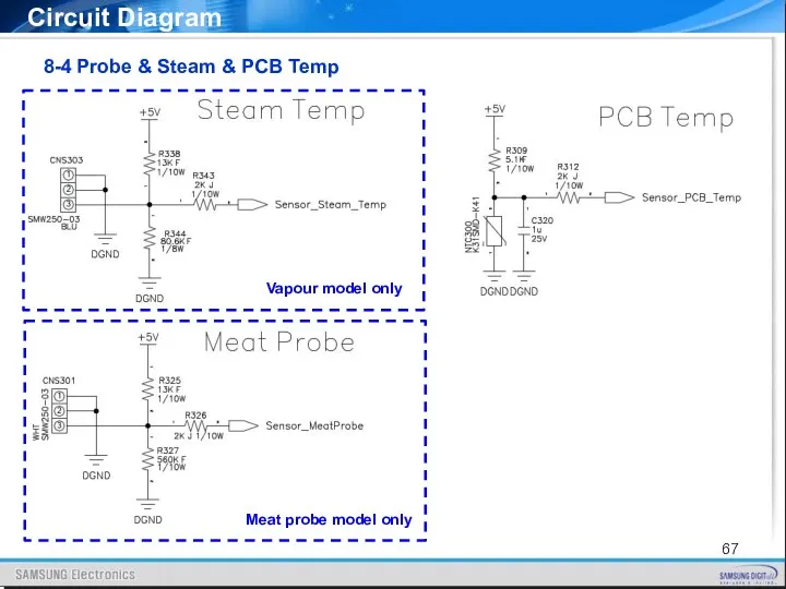
- 67. 8-4 Probe & Steam & PCB Temp Circuit Diagram Vapour model only Meat probe model only
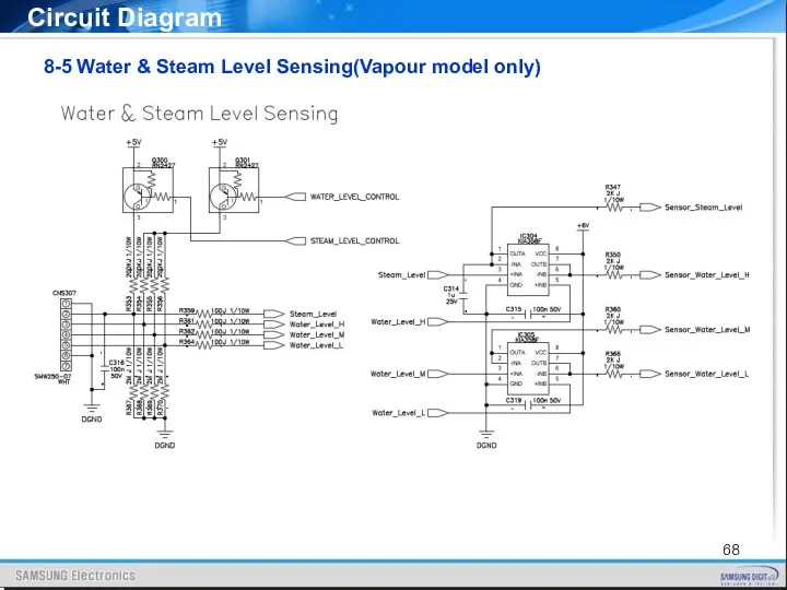
- 68. 8-5 Water & Steam Level Sensing(Vapour model only) Circuit Diagram
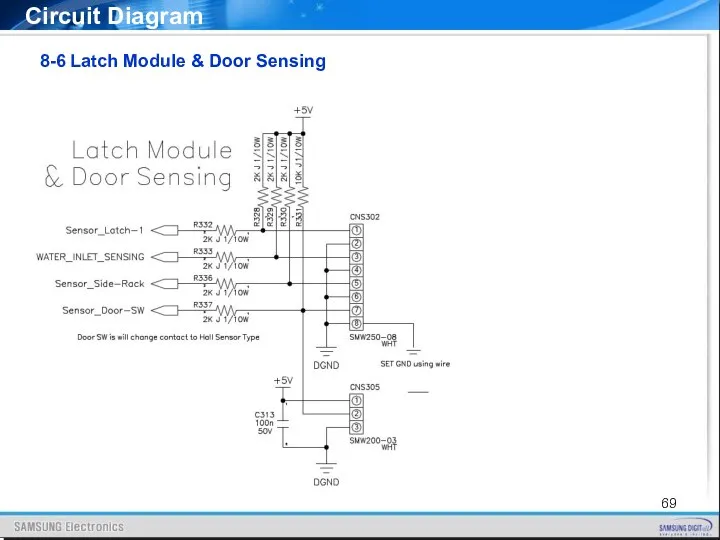
- 69. 8-6 Latch Module & Door Sensing Circuit Diagram
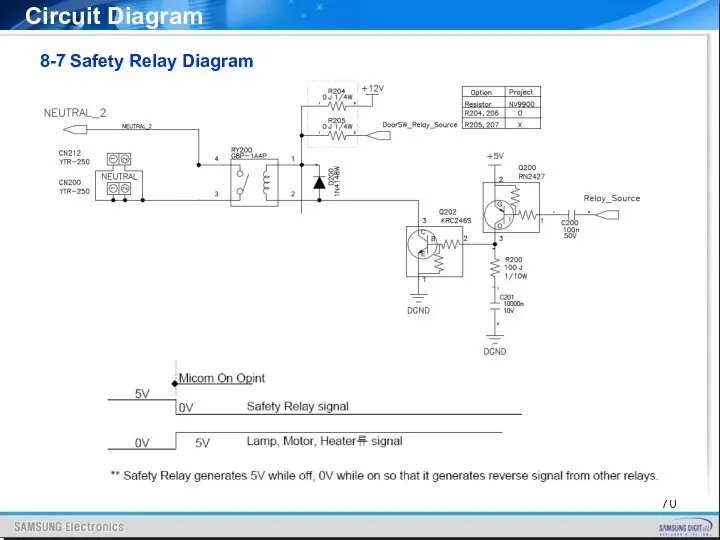
- 70. 8-7 Safety Relay Diagram Circuit Diagram
- 71. 8-8 Relay Operation Diagram Circuit Diagram
- 72. 8-8 Relay Operation Diagram Circuit Diagram
- 73. 8-8 Relay Operation Diagram Circuit Diagram
- 74. 8-9 Over Voltage Protection(OVP model only) Circuit Diagram
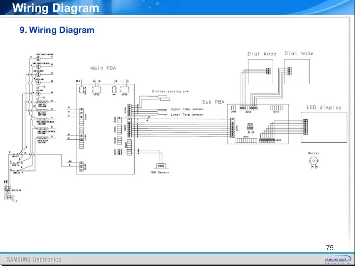
- 75. 9. Wiring Diagram Wiring Diagram
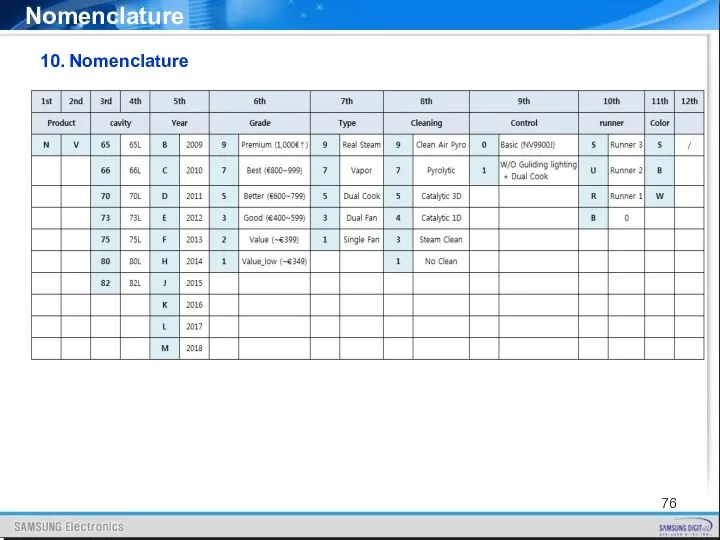
- 76. 10. Nomenclature Nomenclature
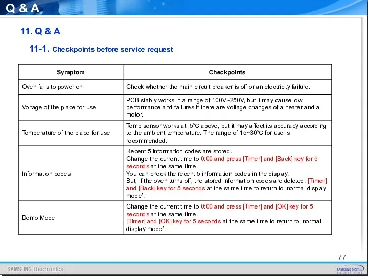
- 77. 11. Q & A Q & A 11-1. Checkpoints before service request
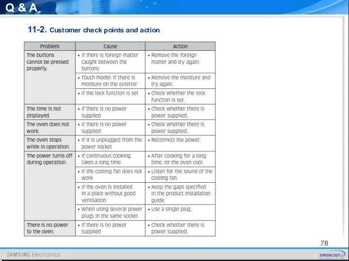
- 78. Q & A 11-2. Customer check points and action
- 79. Q & A 11-2. Customer check points and action
- 80. Q & A 11-2. Customer check points and action
- 81. Q & A 11-2. Customer check points and action
- 83. Скачать презентацию
Precaution
Feature and Specifications
Installation
Function
Service Information
Disassembly and Assembly
Trouble shooting
Circuit Diagram
Wiring Diagram
Nomenclature
Q&A
Contents
Agenda
Feature and Specifications
Installation
Function
Service Information
Disassembly and Assembly
Trouble shooting
Circuit Diagram
Wiring Diagram
Nomenclature
Q&A
Contents
Agenda
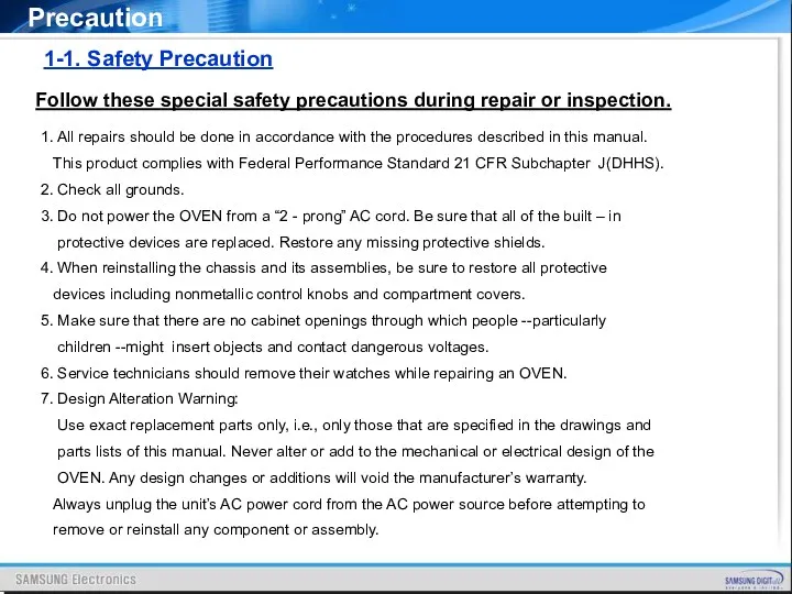
1. All repairs should be done in accordance with the procedures
1. All repairs should be done in accordance with the procedures
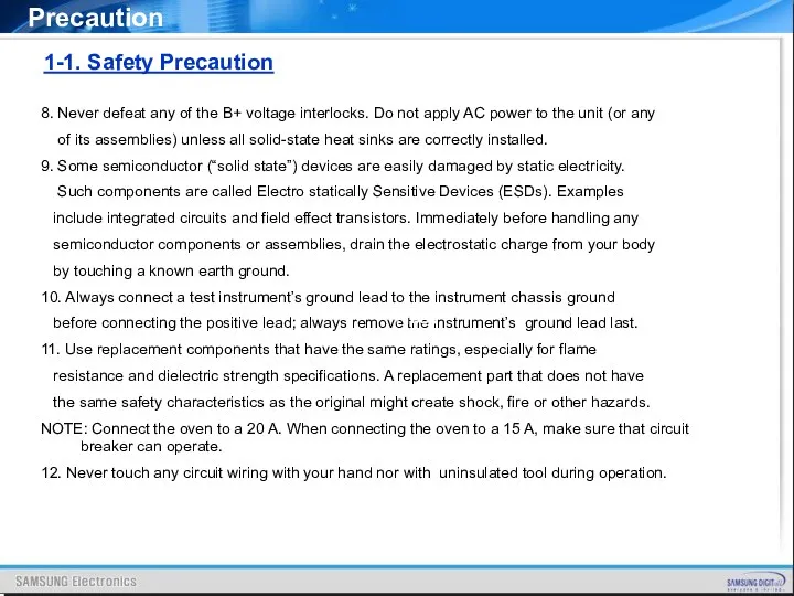
8. Never defeat any of the B+ voltage interlocks. Do not
8. Never defeat any of the B+ voltage interlocks. Do not
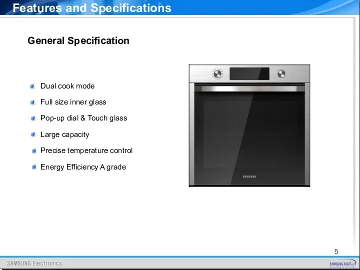
General Specification
Dual cook mode
Full size inner glass
Pop-up
General Specification
Dual cook mode
Full size inner glass
Pop-up
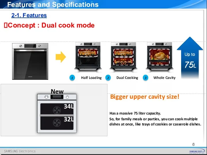
2-1. Features
Features and Specifications
Concept : Dual cook mode
Half Loading
1
Dual Cooking
2
Whole
2-1. Features
Features and Specifications
Concept : Dual cook mode
Half Loading
1
Dual Cooking
2
Whole
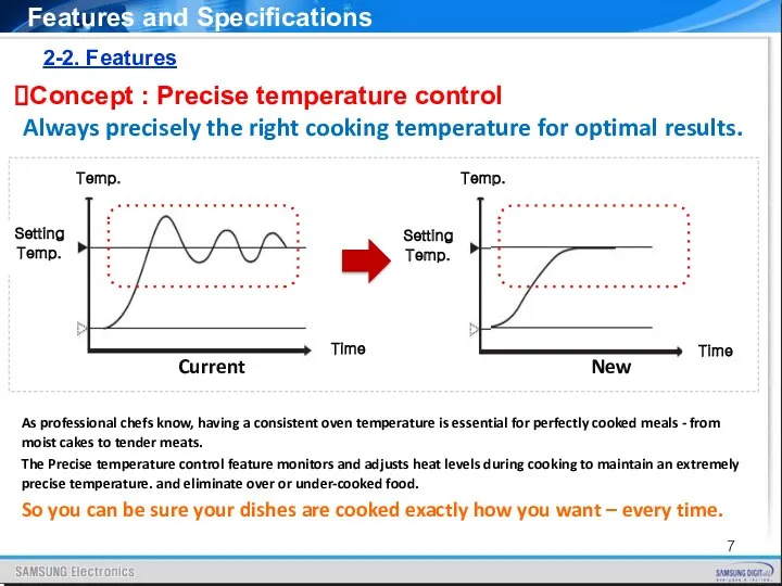
2-2. Features
Concept : Precise temperature control
Always precisely the right cooking temperature
2-2. Features
Concept : Precise temperature control
Always precisely the right cooking temperature
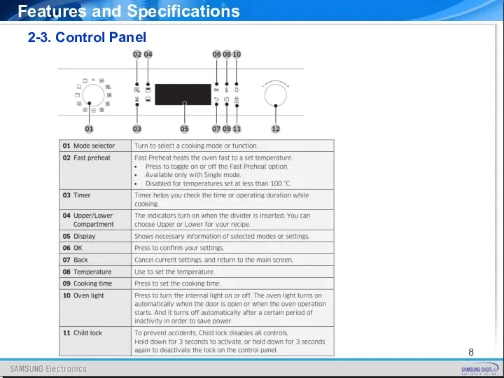
2-3. Control Panel
Features and Specifications
2-3. Control Panel
Features and Specifications
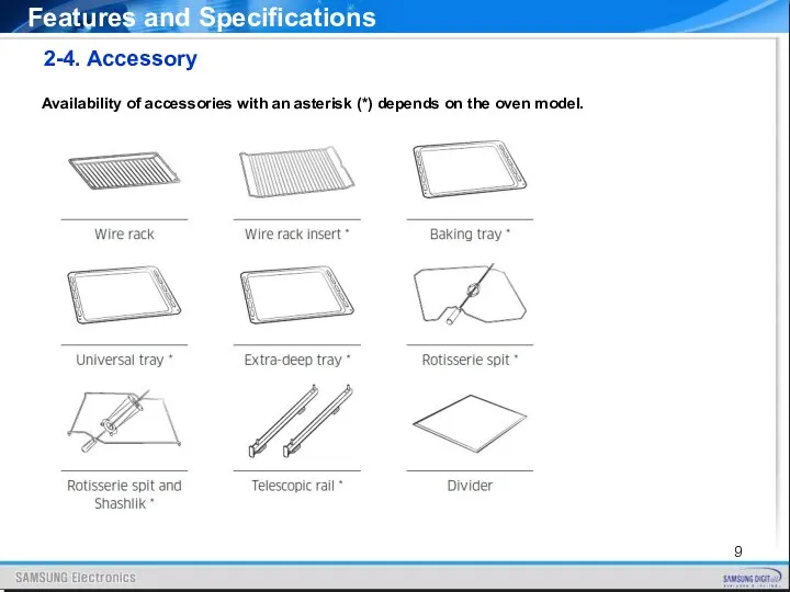
2-4. Accessory
Availability of accessories with an asterisk (*) depends on the
2-4. Accessory
Availability of accessories with an asterisk (*) depends on the
2-4. Accessory
Availability of accessories with an asterisk (*) depends on the
2-4. Accessory
Availability of accessories with an asterisk (*) depends on the
2-4. Accessory
Level of side runners
Insert the accessory to the correct position
2-4. Accessory
Level of side runners
Insert the accessory to the correct position
2-5. Specifications
Features and Specifications
2-5. Specifications
Features and Specifications
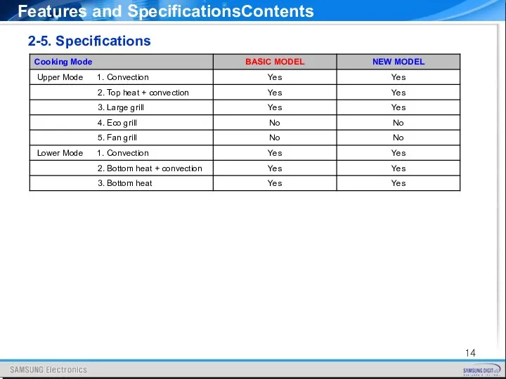
Features and SpecificationsContents
2-5. Specifications
Features and SpecificationsContents
2-5. Specifications
Features and SpecificationsContents
2-5. Specifications
Features and SpecificationsContents
2-5. Specifications
2-5. Specifications
Features and Specifications
2-5. Specifications
Features and Specifications
2-5. Specifications
Features and Specifications
2-5. Specifications
Features and Specifications
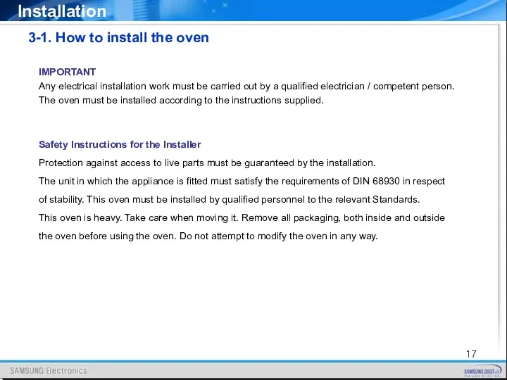
IMPORTANT
Any electrical installation work must be carried out by a qualified
IMPORTANT
Any electrical installation work must be carried out by a qualified
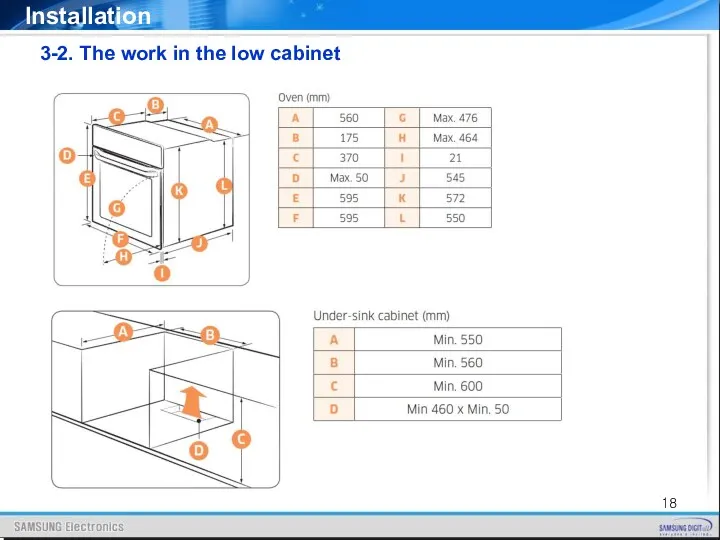
3-2. The work in the low cabinet
Installation
3-2. The work in the low cabinet
Installation
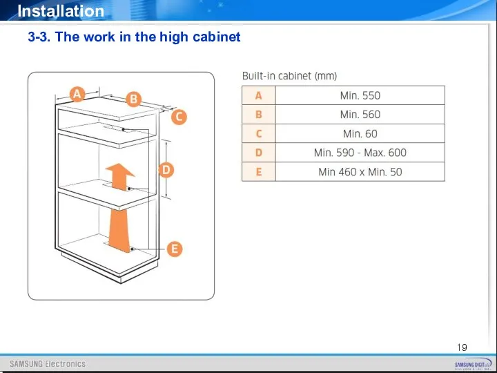
3-3. The work in the high cabinet
Installation
3-3. The work in the high cabinet
Installation
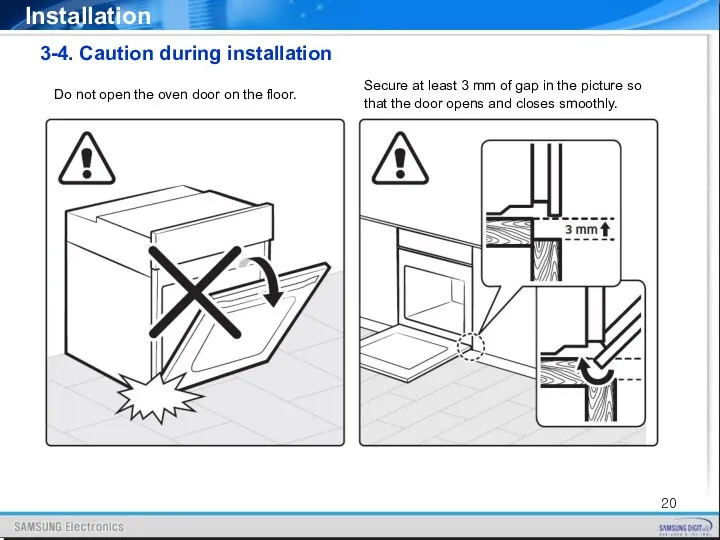
3-4. Caution during installation
Installation
Secure at least 3 mm of
3-4. Caution during installation
Installation
Secure at least 3 mm of
- Connecting the oven to the power supply (H05VV-F, H05RR-F, Min
- Connecting the oven to the power supply (H05VV-F, H05RR-F, Min
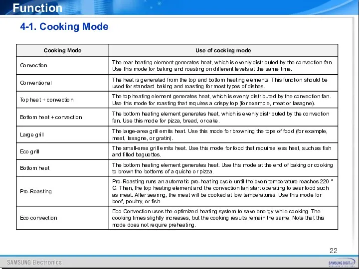
4-1. Cooking Mode
Function
4-1. Cooking Mode
Function
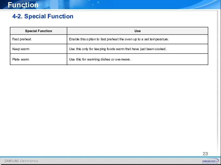
4-2. Special Function
Function
4-2. Special Function
Function
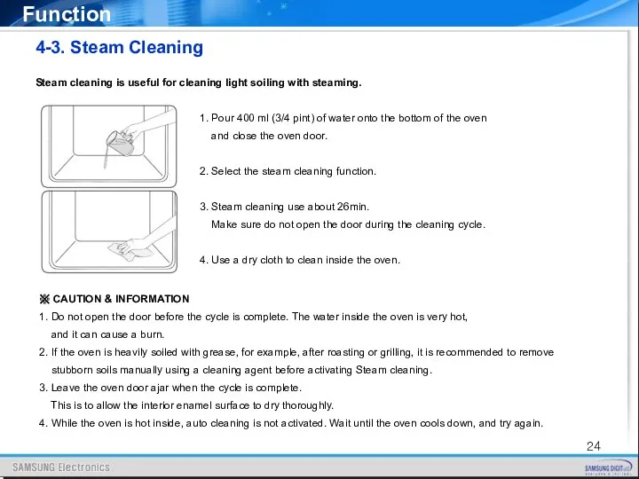
4-3. Steam Cleaning
Function
Steam cleaning is useful for cleaning light soiling
4-3. Steam Cleaning
Function
Steam cleaning is useful for cleaning light soiling
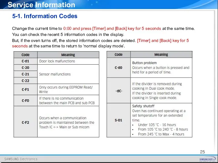
5-1. Information Codes
Service Information
Change the current time to 0:00 and
5-1. Information Codes
Service Information
Change the current time to 0:00 and
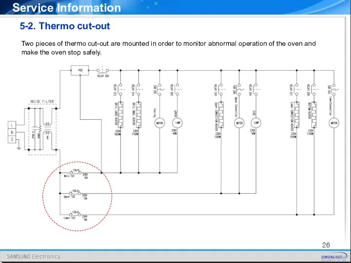
5-2. Thermo cut-out
Two pieces of thermo cut-out are mounted in order
5-2. Thermo cut-out
Two pieces of thermo cut-out are mounted in order
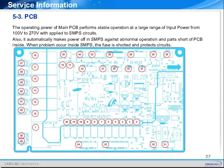
5-3. PCB
The operating power of Main PCB performs stable operation at
5-3. PCB
The operating power of Main PCB performs stable operation at
5-3. PCB
Service Information
5-3. PCB
Service Information
5-3. PCB
Service Information
5-3. PCB
Service Information
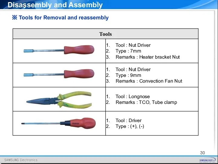
※ Tools for Removal and reassembly
Disassembly and Assembly
※ Tools for Removal and reassembly
Disassembly and Assembly
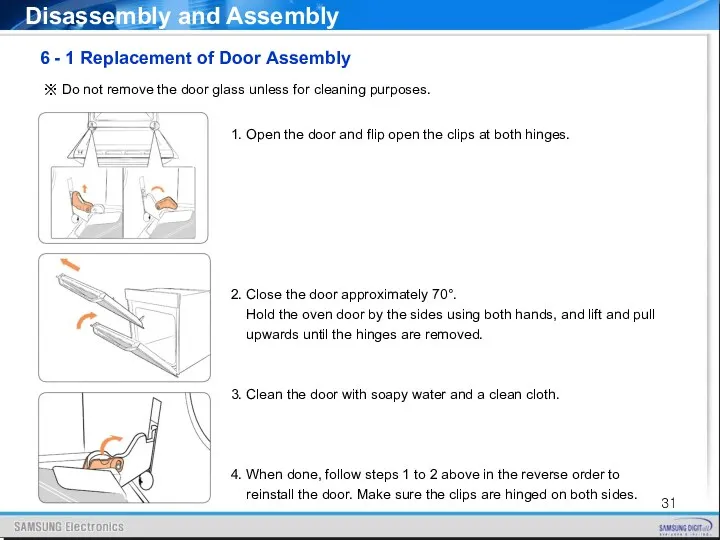
6 - 1 Replacement of Door Assembly
Disassembly and Assembly
1. Open
6 - 1 Replacement of Door Assembly
Disassembly and Assembly
1. Open
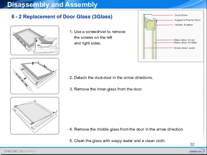
6 - 2 Replacement of Door Glass (3Glass)
Disassembly and Assembly
1.
6 - 2 Replacement of Door Glass (3Glass)
Disassembly and Assembly
1.
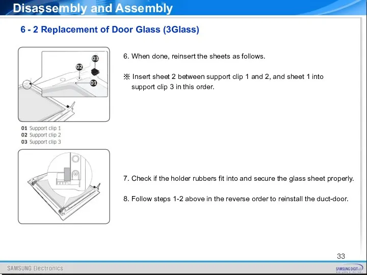
Disassembly and Assembly
6 - 2 Replacement of Door Glass (3Glass)
6.
Disassembly and Assembly
6 - 2 Replacement of Door Glass (3Glass)
6.
1. Take off the cap by turning counterclockwise.
2. Remove the metal
1. Take off the cap by turning counterclockwise.
2. Remove the metal
6 - 4 Replacement of Assy Control Box
Disassembly and
6 - 4 Replacement of Assy Control Box
Disassembly and
Disassembly and Assembly
1. Remove some connectors from circled part in
Disassembly and Assembly
1. Remove some connectors from circled part in
Disassembly and Assembly
※ Parts with Control-box
6 - 4 Replacement
Disassembly and Assembly
※ Parts with Control-box
6 - 4 Replacement
Disassembly and Assembly
6 - 4 Replacement of Assy Control Box
Disassembly and Assembly
6 - 4 Replacement of Assy Control Box
Disassembly and Assembly
※ Parts with Control-box
6 - 4 Replacement
Disassembly and Assembly
※ Parts with Control-box
6 - 4 Replacement
Disassembly and Assembly
6 – 5 Replacement of Motor fan cooling
1.
Disassembly and Assembly
6 – 5 Replacement of Motor fan cooling
1.
6 - 6 Replacement of Assy cover Air
Disassembly and Assembly
1.
6 - 6 Replacement of Assy cover Air
Disassembly and Assembly
1.
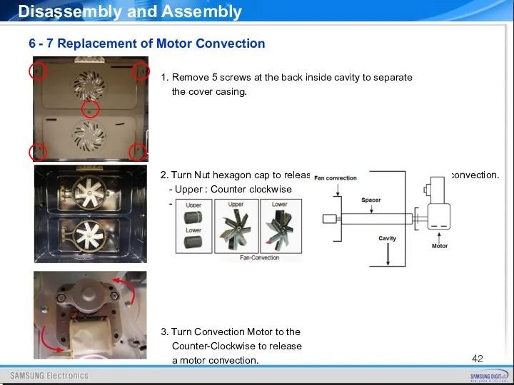
1. Remove 5 screws at the back inside cavity to separate
1. Remove 5 screws at the back inside cavity to separate
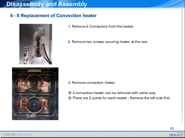
6 - 8 Replacement of Convection heater
Disassembly and Assembly
1. Remove
6 - 8 Replacement of Convection heater
Disassembly and Assembly
1. Remove
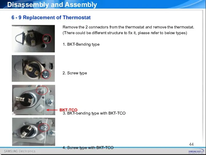
6 - 9 Replacement of Thermostat
Disassembly and Assembly
Remove the 2
6 - 9 Replacement of Thermostat
Disassembly and Assembly
Remove the 2
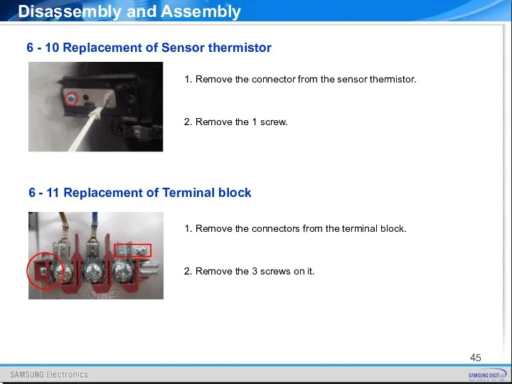
6 - 11 Replacement of Terminal block
Disassembly and Assembly
6 -
6 - 11 Replacement of Terminal block
Disassembly and Assembly
6 -
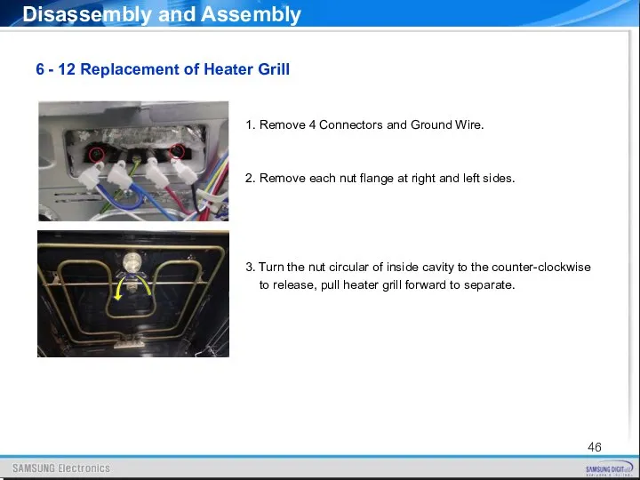
1. Remove 4 Connectors and Ground Wire.
2. Remove each nut flange
1. Remove 4 Connectors and Ground Wire.
2. Remove each nut flange
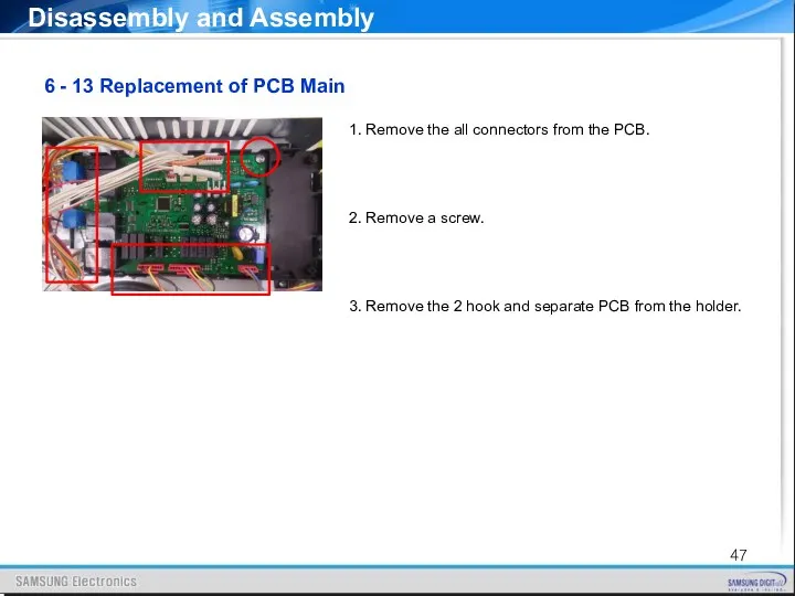
6 - 13 Replacement of PCB Main
Disassembly and Assembly
1. Remove
6 - 13 Replacement of PCB Main
Disassembly and Assembly
1. Remove
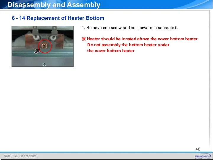
1. Remove one screw and pull forward to separate it.
※ Heater
1. Remove one screw and pull forward to separate it.
※ Heater
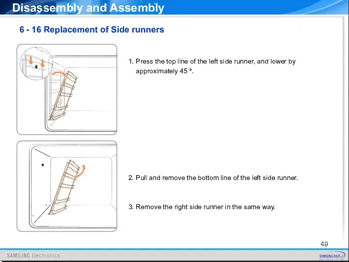
6 - 16 Replacement of Side runners
Disassembly and Assembly
1. Press
6 - 16 Replacement of Side runners
Disassembly and Assembly
1. Press
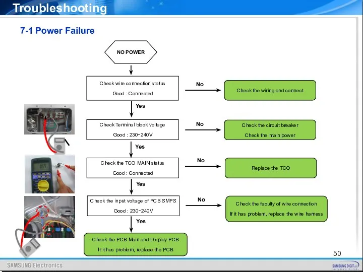
7-1 Power Failure
Troubleshooting
NO POWER
Check Terminal block voltage
Good : 230~240V
Check the
7-1 Power Failure
Troubleshooting
NO POWER
Check Terminal block voltage
Good : 230~240V
Check the
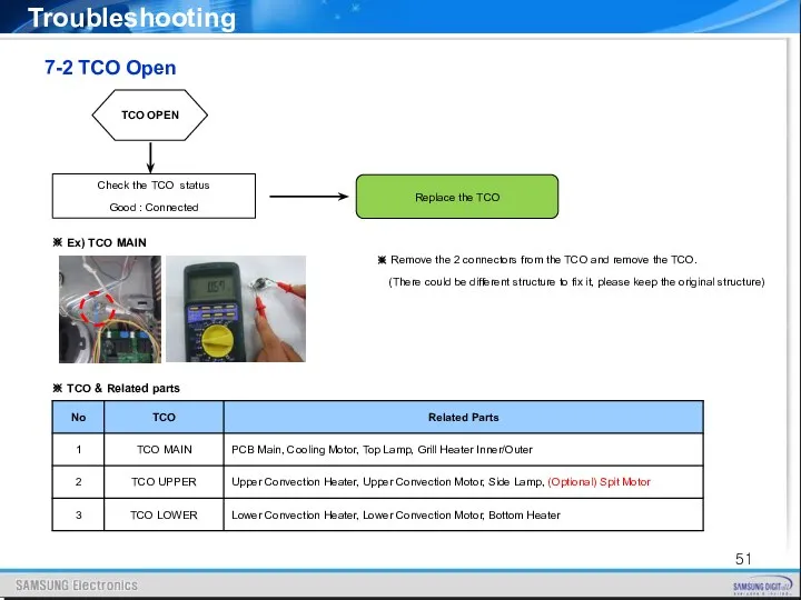
7-2 TCO Open
Troubleshooting
TCO OPEN
Check the TCO status
Good : Connected
Replace the
7-2 TCO Open
Troubleshooting
TCO OPEN
Check the TCO status
Good : Connected
Replace the
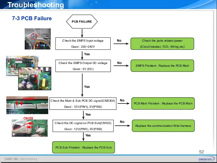
7-3 PCB Failure
Troubleshooting
PCB FAILURE
Check the SMPS Input voltage
Good : 230~240V
Check
7-3 PCB Failure
Troubleshooting
PCB FAILURE
Check the SMPS Input voltage
Good : 230~240V
Check
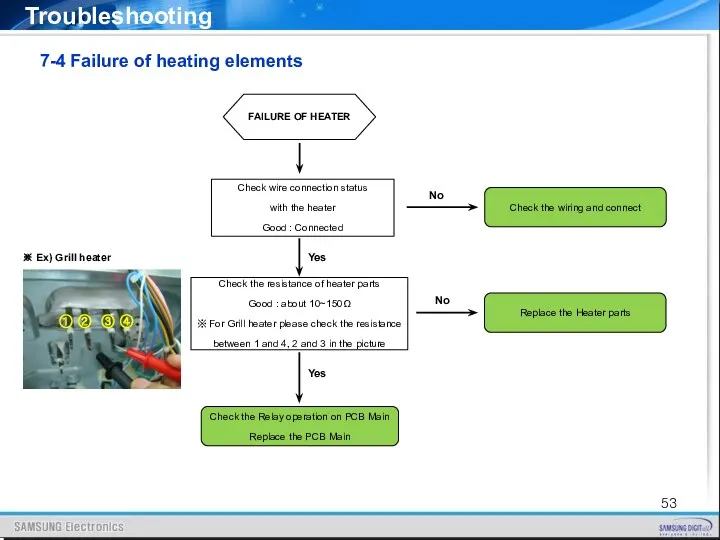
7-4 Failure of heating elements
Troubleshooting
FAILURE OF HEATER
Check wire connection status
7-4 Failure of heating elements
Troubleshooting
FAILURE OF HEATER
Check wire connection status

7-5 Failure of Motor parts
Troubleshooting
FAILURE OF MOTOR
Check wire connection status
7-5 Failure of Motor parts
Troubleshooting
FAILURE OF MOTOR
Check wire connection status
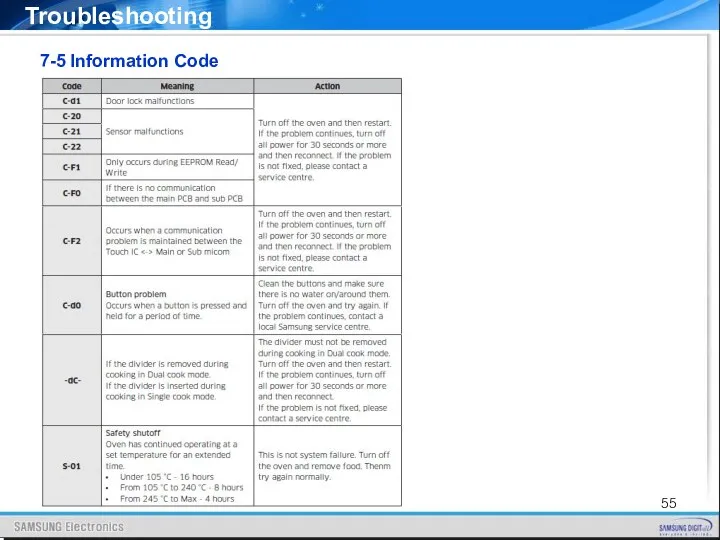
7-5 Information Code
Troubleshooting
7-5 Information Code
Troubleshooting
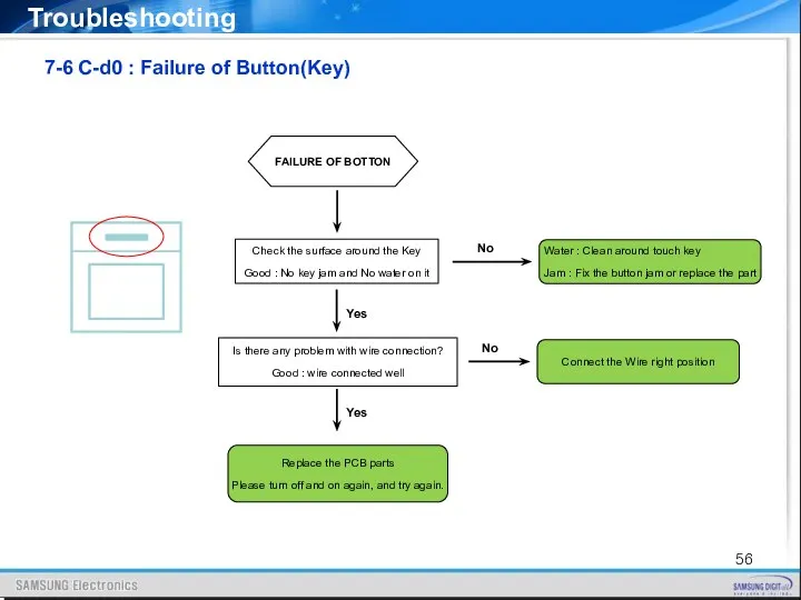
7-6 C-d0 : Failure of Button(Key)
Troubleshooting
FAILURE OF BOTTON
Check the surface
7-6 C-d0 : Failure of Button(Key)
Troubleshooting
FAILURE OF BOTTON
Check the surface
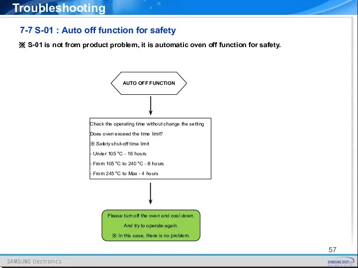
7-7 S-01 : Auto off function for safety
Troubleshooting
AUTO OFF FUNCTION
Check
7-7 S-01 : Auto off function for safety
Troubleshooting
AUTO OFF FUNCTION
Check
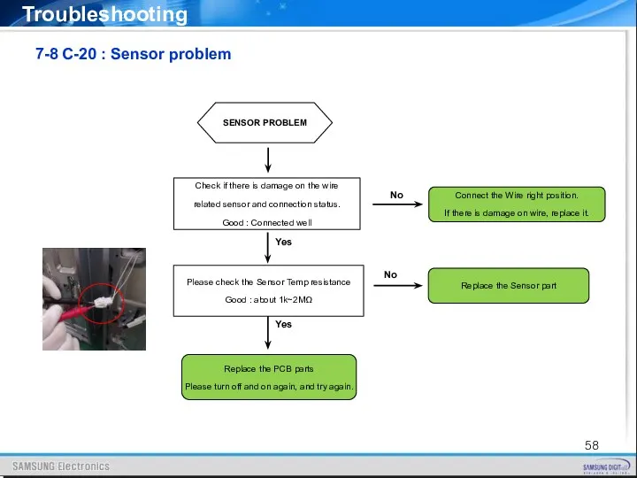
7-8 C-20 : Sensor problem
Troubleshooting
SENSOR PROBLEM
Check if there is damage
7-8 C-20 : Sensor problem
Troubleshooting
SENSOR PROBLEM
Check if there is damage
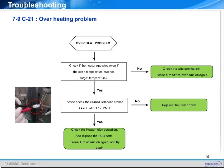
7-9 C-21 : Over heating problem
Troubleshooting
OVER HEAT PROBLEM
Check if the
7-9 C-21 : Over heating problem
Troubleshooting
OVER HEAT PROBLEM
Check if the
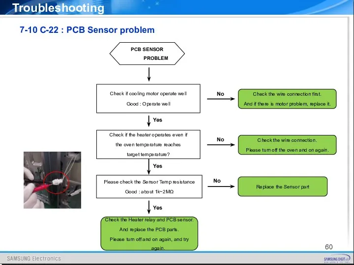
7-10 C-22 : PCB Sensor problem
Troubleshooting
PCB SENSOR PROBLEM
Check if cooling
7-10 C-22 : PCB Sensor problem
Troubleshooting
PCB SENSOR PROBLEM
Check if cooling
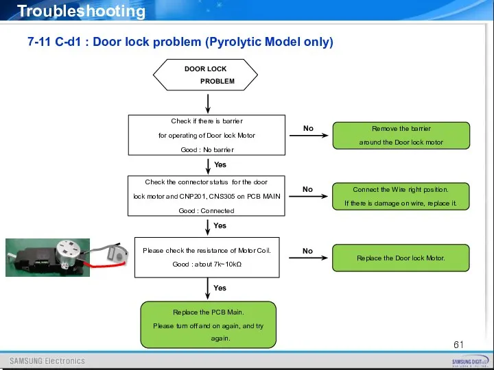
7-11 C-d1 : Door lock problem (Pyrolytic Model only)
Troubleshooting
DOOR LOCK
7-11 C-d1 : Door lock problem (Pyrolytic Model only)
Troubleshooting
DOOR LOCK
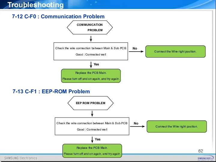
7-12 C-F0 : Communication Problem
Troubleshooting
COMMUNICATION PROBLEM
7-13 C-F1 : EEP-ROM Problem
EEP
7-12 C-F0 : Communication Problem
Troubleshooting
COMMUNICATION PROBLEM
7-13 C-F1 : EEP-ROM Problem
EEP
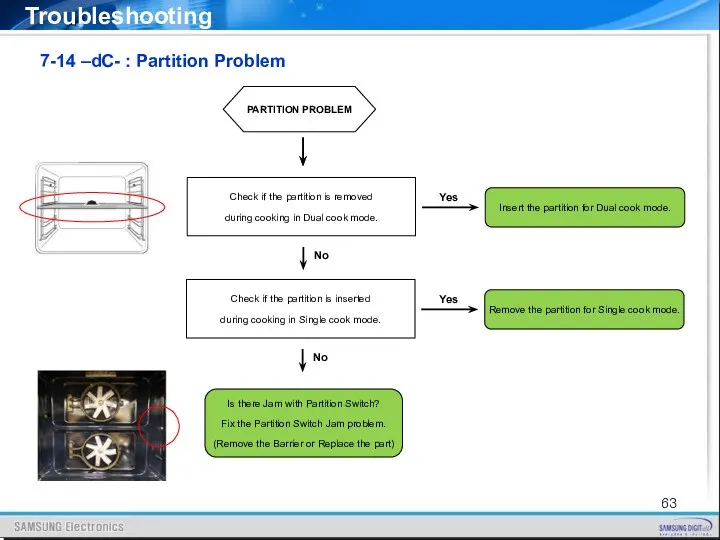
7-14 –dC- : Partition Problem
Troubleshooting
PARTITION PROBLEM
Check if the partition is
7-14 –dC- : Partition Problem
Troubleshooting
PARTITION PROBLEM
Check if the partition is
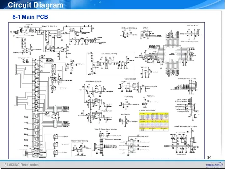
8-1 Main PCB
Circuit Diagram
8-1 Main PCB
Circuit Diagram
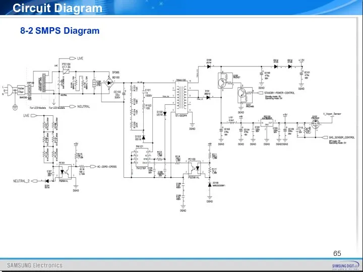
8-2 SMPS Diagram
Circuit Diagram
8-2 SMPS Diagram
Circuit Diagram
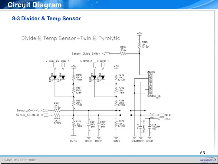
8-3 Divider & Temp Sensor
Circuit Diagram
8-3 Divider & Temp Sensor
Circuit Diagram
8-4 Probe & Steam & PCB Temp
Circuit Diagram
Vapour model only
Meat
8-4 Probe & Steam & PCB Temp
Circuit Diagram
Vapour model only
Meat
8-5 Water & Steam Level Sensing(Vapour model only)
Circuit Diagram
8-5 Water & Steam Level Sensing(Vapour model only)
Circuit Diagram
8-6 Latch Module & Door Sensing
Circuit Diagram
8-6 Latch Module & Door Sensing
Circuit Diagram
8-7 Safety Relay Diagram
Circuit Diagram
8-7 Safety Relay Diagram
Circuit Diagram
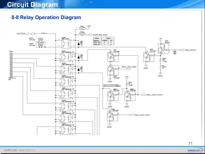
8-8 Relay Operation Diagram
Circuit Diagram
8-8 Relay Operation Diagram
Circuit Diagram
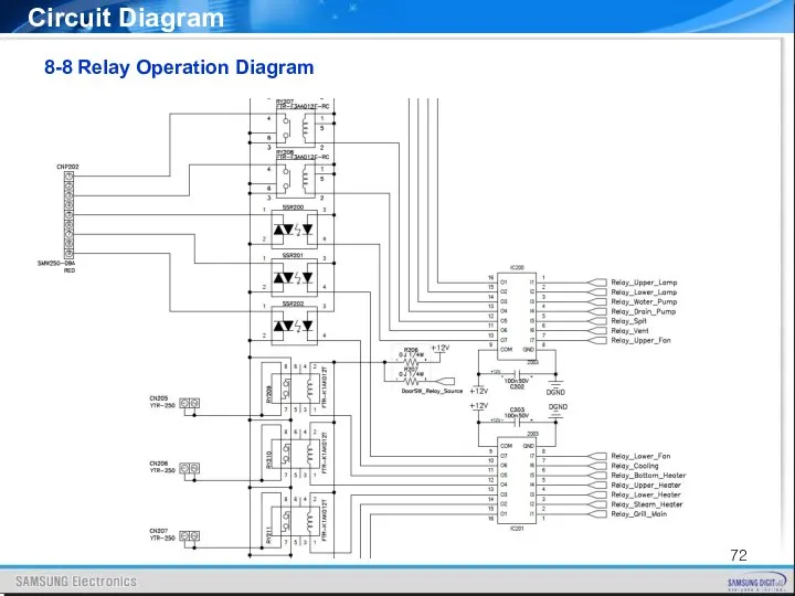
8-8 Relay Operation Diagram
Circuit Diagram
8-8 Relay Operation Diagram
Circuit Diagram
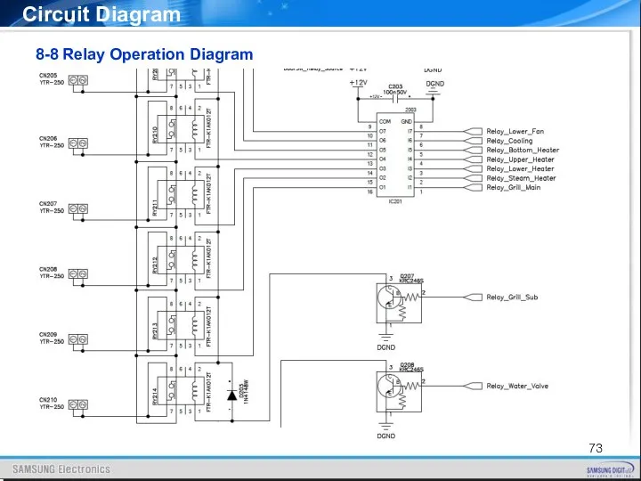
8-8 Relay Operation Diagram
Circuit Diagram
8-8 Relay Operation Diagram
Circuit Diagram
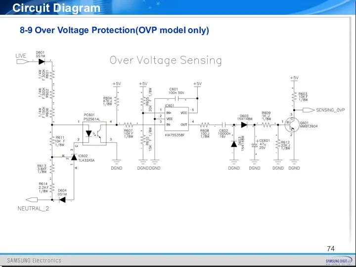
8-9 Over Voltage Protection(OVP model only)
Circuit Diagram
8-9 Over Voltage Protection(OVP model only)
Circuit Diagram
9. Wiring Diagram
Wiring Diagram
9. Wiring Diagram
Wiring Diagram
10. Nomenclature
Nomenclature
10. Nomenclature
Nomenclature
11. Q & A
Q & A
11-1. Checkpoints before service request
11. Q & A
Q & A
11-1. Checkpoints before service request
Q & A
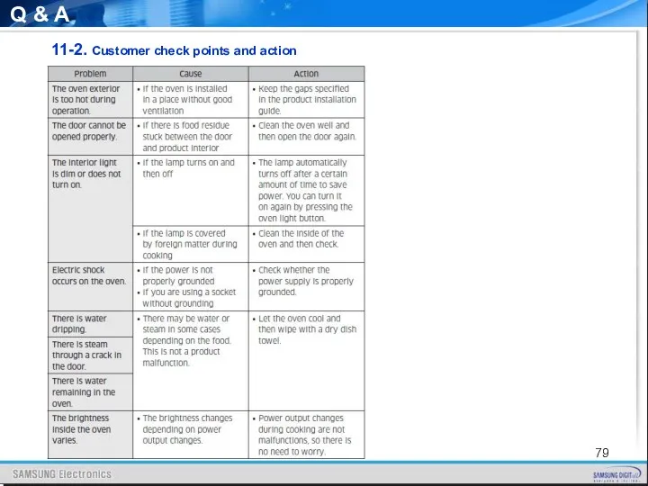
11-2. Customer check points and action
Q & A
11-2. Customer check points and action
Q & A
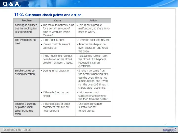
11-2. Customer check points and action
Q & A
11-2. Customer check points and action
Q & A
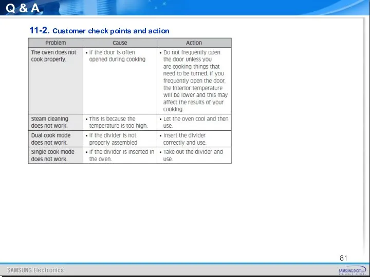
11-2. Customer check points and action
Q & A
11-2. Customer check points and action
Q & A
11-2. Customer check points and action
Q & A
11-2. Customer check points and action
 Уроженцы Бабушкинского района - Герои Советского Союза
 Парадоксы жизни
 Тест по теме Арктические пустыни, тундра, лесотундра
 Образовательной программы дошкольной образовательной организации
 ТРЕНАЖЕРНО- ИНФОРМАЦИОННАЯ СИСТЕМА ТИСА В ШКОЛЬНОЙ ПРОГРАММЕ НА УРОКАХ ЛФК
 Dwayne Douglas Johnson
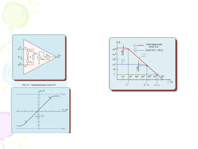 Операционные усилители
 Бизнес-планирование. Модуль 6
 Похититель рассудка
 Осложнения повреждений опорно-двигательного аппарата
 Past Simple
 speakout
 Жилища народов России в старину
 Спектры и спектральный анализ
 Заболевания сердечно-сосудистой системы
 Достижения педагога
 Эксперту: Структура и содержание устной части
 дыхательная недостаточность
 fb-5fa0bf70
 Презентация Развиваем мелкую моторику рук
 Презентация Озера
 Массаж
 Дополнительные авторские программы художественно - эстетической направленности: ХУДОЖЕСТВЕННЫЙ ЯЗЫК ИЗОБРАЗИТЕЛЬНОГО ИСКУССТВА, СМОТРЮ НА МИР ГЛАЗАМИ ХУДОЖНИКА, ВОЛШЕБНЫЕ СЕКРЕТЫ ХУДОЖНИКА, В МИРЕ ХУДОЖ
 Tsesnabank
 Технология культурных практик (коллекционирование)
 Военно-промышленный комплекс
 Понятие об органах растений. Корень
 РАЗВИВАЮЩАЯ СРЕДА В КОРРЕКЦИОННОЙ ГРУППЕ ЗНАЙКИ ПО ФГОС