- Operation, installation, and troubleshooting of the LNCS

Содержание
- 2. Description of Operation Liquid nitrogen from a supply reservoir is fed through an inlet tube into
- 3. Description of Operation The Liquid detection/evaporator (diagnostic signal #9) assembly includes a liquid detector capable of
- 4. Description of Operation When liquid has been detected, in the liquid detect/evaporator assembly, droplets passing over
- 5. Description of Operation In this design, the evaporator can not only evaporates droplets of cooling agent
- 6. Inside the cooling head Liquid Detect / Evaporator Outlet / Exhaust tube Anti-condensation heaters Heat Exchanger
- 7. Components of the LNCS COMPONENT DESCRIPTION ANTI-CONDENSATION STRIP HEATERS Both strip heaters use 24V and are
- 8. Components of the LNCS INLET TUBE Transfers liquid Nitrogen from the LNCS dewar to the heat
- 9. Components of the LNCS LIQUID NITROGEN DETECTION - EVAPORATOR ASSEMBLY The liquid detect/evaporator assembly detects and
- 10. Components of the LNCS (Liquid Detect) Exhaust from the heat exchanger enters here Exhaust port Liquid
- 11. LNCS Pressure Control
- 12. LNCS Pressure range Coolant pressure requirements will vary with the heat load on the heat exchanger,
- 13. Dewar pressure control The dewar pressure is controlled by a pressure control valve assembly, which regulates
- 14. Calibrating the LNCS
- 15. The LNCS control screen
- 16. The LNCS calibration screen
- 17. Calibrating the LNCS To calibrate the LNCS before using it, follow these steps: 1. Select Menu/Control
- 18. Calibrating the LNCS 5. Click on the Commands pull down menu. Select Fill to the Neck.
- 19. Calibrating the LNCS 10. Ensure that the Master Calibration Control is set to “Use Current Cal
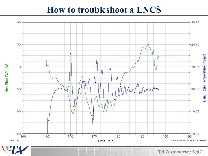
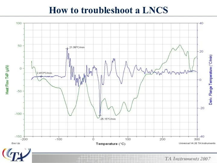
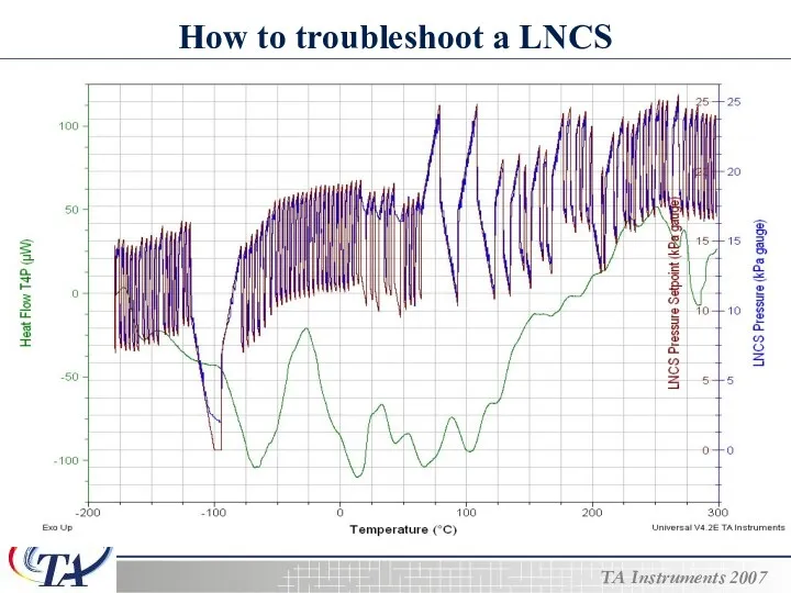
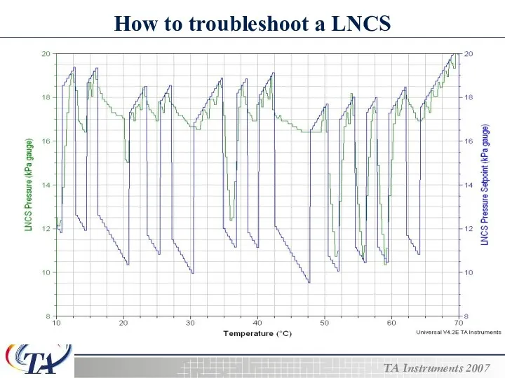
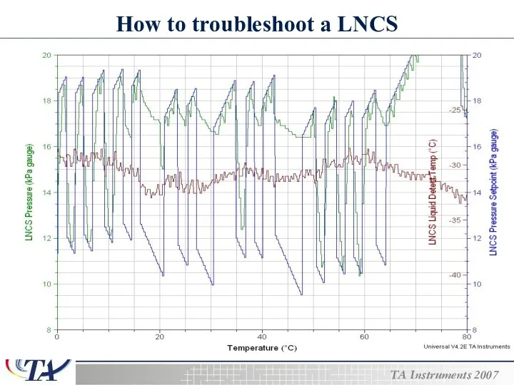
- 20. How to troubleshoot a LNCS Troubleshooting a LNCS system adds another layer of complexity to an
- 21. How to troubleshoot a LNCS The signals used to troubleshoot a LNCS are…. The Heat Flow
- 22. How to troubleshoot a LNCS
- 23. How to troubleshoot a LNCS
- 24. How to troubleshoot a LNCS
- 25. How to troubleshoot a LNCS
- 26. How to troubleshoot a LNCS
- 28. Скачать презентацию
Description of Operation
Liquid nitrogen from a supply reservoir is fed through
Description of Operation
Liquid nitrogen from a supply reservoir is fed through
Description of Operation
The Liquid detection/evaporator (diagnostic signal #9) assembly includes a
Description of Operation
The Liquid detection/evaporator (diagnostic signal #9) assembly includes a
Description of Operation
When liquid has been detected, in the liquid detect/evaporator
Description of Operation
When liquid has been detected, in the liquid detect/evaporator
Description of Operation
In this design, the evaporator can not only evaporates
Description of Operation
In this design, the evaporator can not only evaporates
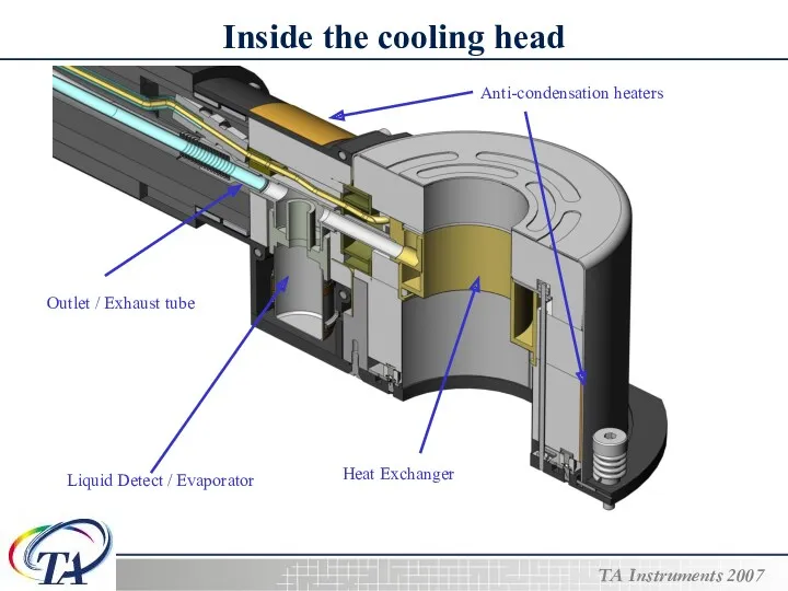
Inside the cooling head
Liquid Detect / Evaporator
Outlet / Exhaust tube
Anti-condensation heaters
Heat
Inside the cooling head
Liquid Detect / Evaporator
Outlet / Exhaust tube
Anti-condensation heaters
Heat
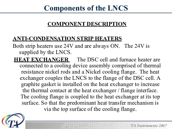
Components of the LNCS
COMPONENT DESCRIPTION
ANTI-CONDENSATION STRIP HEATERS
Both strip heaters use
Components of the LNCS
COMPONENT DESCRIPTION
ANTI-CONDENSATION STRIP HEATERS
Both strip heaters use
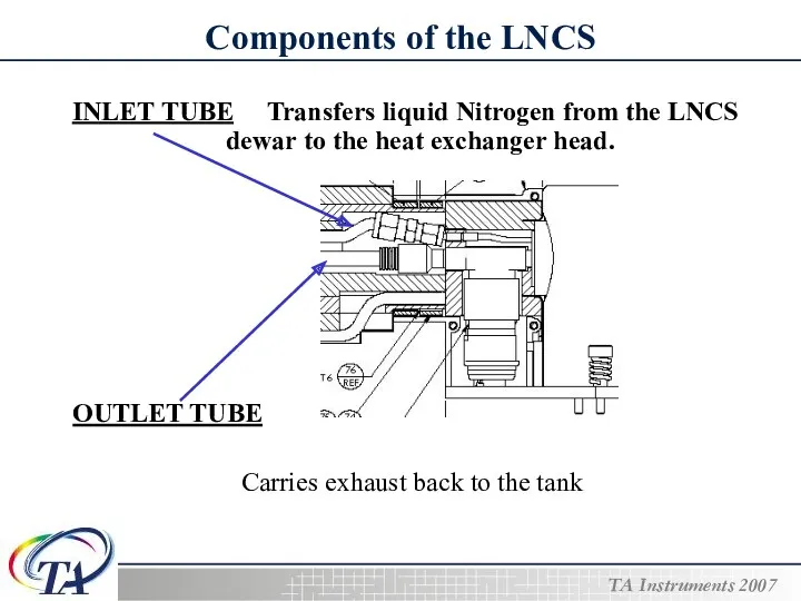
Components of the LNCS
INLET TUBE Transfers liquid Nitrogen from the LNCS
Components of the LNCS
INLET TUBE Transfers liquid Nitrogen from the LNCS
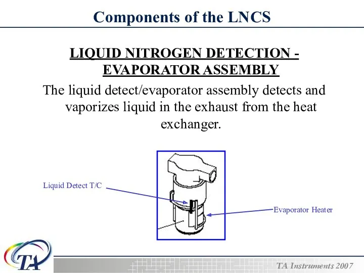
Components of the LNCS
LIQUID NITROGEN DETECTION - EVAPORATOR ASSEMBLY
The liquid
Components of the LNCS
LIQUID NITROGEN DETECTION - EVAPORATOR ASSEMBLY
The liquid
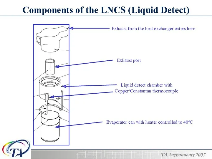
Components of the LNCS (Liquid Detect)
Exhaust from the heat exchanger enters
Components of the LNCS (Liquid Detect)
Exhaust from the heat exchanger enters
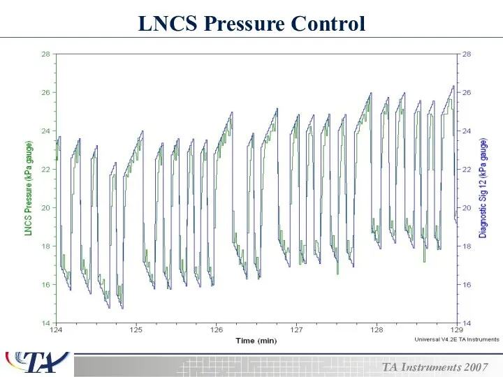
LNCS Pressure Control
LNCS Pressure Control
LNCS Pressure range
Coolant pressure requirements will vary with the heat load
LNCS Pressure range
Coolant pressure requirements will vary with the heat load
Dewar pressure control
The dewar pressure is controlled by a pressure control
Dewar pressure control
The dewar pressure is controlled by a pressure control
Calibrating the LNCS
Calibrating the LNCS
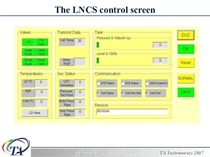
The LNCS control screen
The LNCS control screen
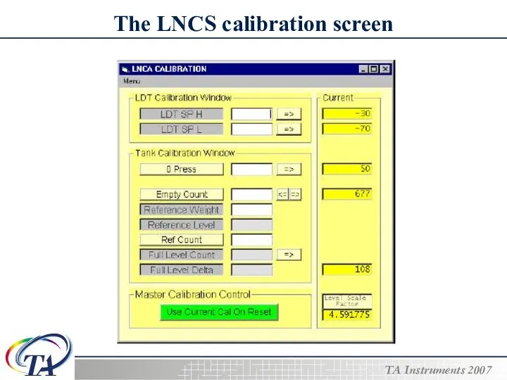
The LNCS calibration screen
The LNCS calibration screen
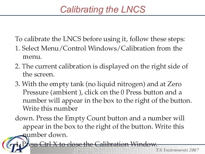
Calibrating the LNCS
To calibrate the LNCS before using it, follow these
Calibrating the LNCS
To calibrate the LNCS before using it, follow these
Calibrating the LNCS
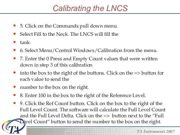
5. Click on the Commands pull down menu.
Select Fill
Calibrating the LNCS
5. Click on the Commands pull down menu.
Select Fill
Calibrating the LNCS
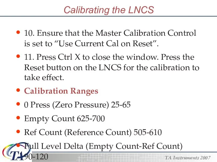
10. Ensure that the Master Calibration Control is set
Calibrating the LNCS
10. Ensure that the Master Calibration Control is set
How to troubleshoot a LNCS
Troubleshooting a LNCS system adds another layer
How to troubleshoot a LNCS
Troubleshooting a LNCS system adds another layer
How to troubleshoot a LNCS
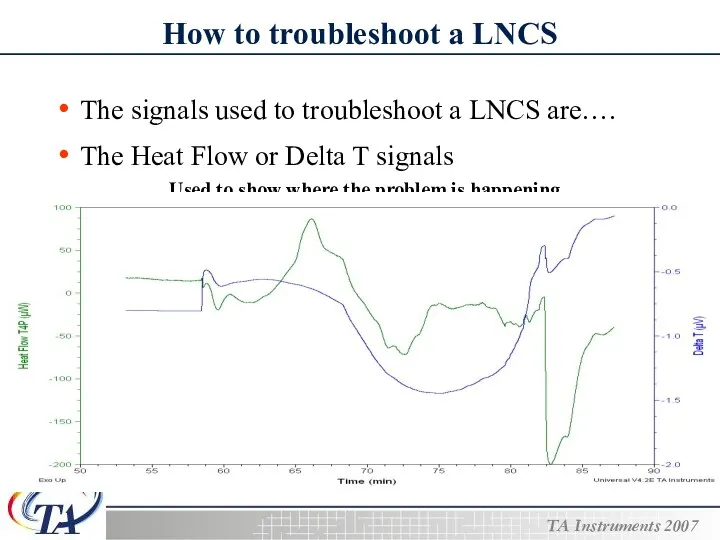
The signals used to troubleshoot a LNCS
How to troubleshoot a LNCS
The signals used to troubleshoot a LNCS
How to troubleshoot a LNCS
How to troubleshoot a LNCS
How to troubleshoot a LNCS
How to troubleshoot a LNCS
How to troubleshoot a LNCS
How to troubleshoot a LNCS
How to troubleshoot a LNCS
How to troubleshoot a LNCS
How to troubleshoot a LNCS
How to troubleshoot a LNCS
 Презентация Әлифба бәйрәме
 Тренажёр - презентация Состав слова
 Металлургия және машина жасау өнеркәсібі
 Почему дует ветер
 Презентация. Растительный мир России, 8 класс.
 The Cry of a Wounded Heart
 Основные принципы переливания крови
 Управление качеством эксплуатации объектов теплоэнергетики
 Классификация информационных систем
 Сестринский уход при гломерулонефритах
 Рамка и основная надпись чертежа, для школ 8 вида
 Сестринский процесс при уходе за недоношенным ребенком. Лекция 2
 Построение выреза детали ¼
 Познавательное развитие в соответствии с ФГОС .
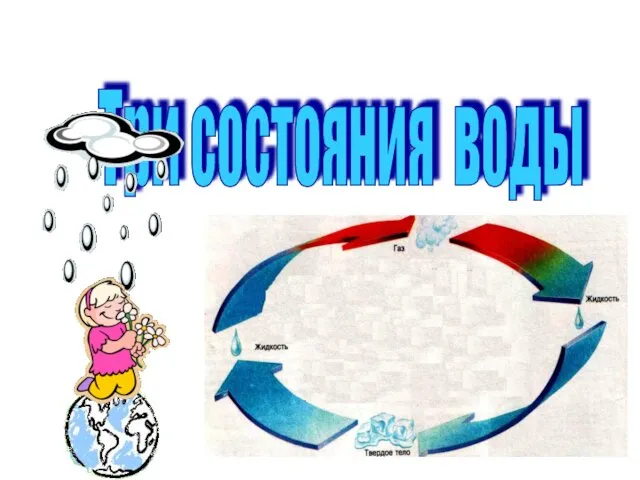 Три состояния воды
 Как развивать внимание ? (часть 4)
 Первая помощь при повреждении грудной клетки и живота
 Контроль сварных соединений
 Минеральное питание растений
 Михаил Юрьевич Лермонтов
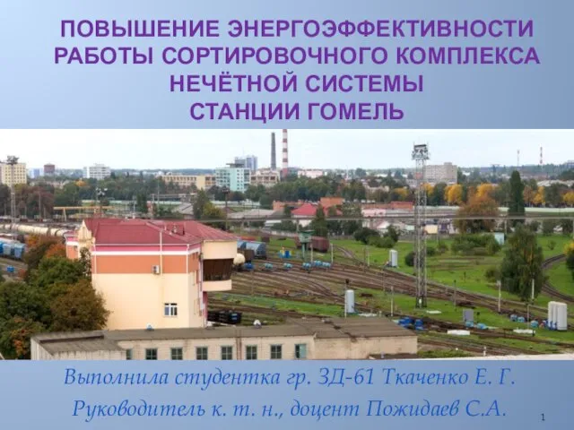 Повышение энергоэффективности работы сортировочного комплекса Нечётной системы станции Гомель
 Метод моделирования на уроках географии
 Основные понятия Управления проектами
 Методы исследования механической активности сердца
 Презентация аналитического отчёта
 Строение Земли. Горные породы
 Автоматизация звука [Р]
 ЗДОРОВЬСБЕРЕГАЮЩИЕ ТЕХНОЛОГИИ НА УРОКАХ ГЕОГРАФИИ