- PAP5300 service manual

Содержание
- 2. content 1、 Product introduce..………..p3-p5 2、 Disassembly guide ……….p6-p20 3、 Repairing guide …………...p21-p31
- 3. Product introduce
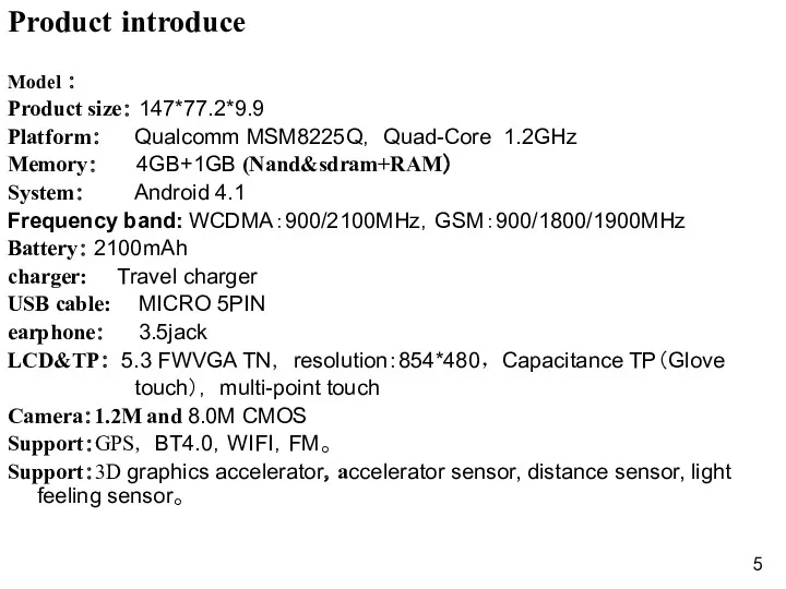
- 5. Product introduce Model : Product size: 147*77.2*9.9 Platform: Qualcomm MSM8225Q, Quad-Core 1.2GHz Memory: 4GB+1GB (Nand&sdram+RAM) System:
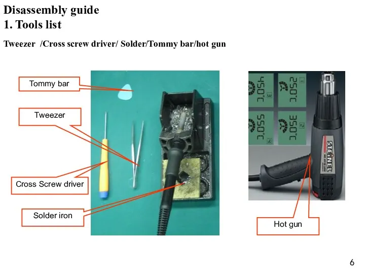
- 6. Hot gun 1. Tools list Tweezer /Cross screw driver/ Solder/Tommy bar/hot gun Disassembly guide
- 7. 2. Battery caver disassembly open the battery cover,as the Fig. 1 Fig. 1 Disassembly guide Battery
- 8. 3. Back caver disassembly 1) Unscrew 7 screws in back cover ,as the Fig.2; Fig. 2
- 9. Fig. 3 2) Disassemble back cover with Tommy bar ,as the Fig.3; Disassembly guide Back cover
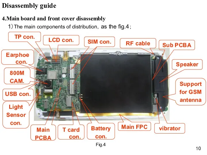
- 10. 4.Main board and front cover disassembly 1)The main components of distribution,as the fig.4; Fig.4 Disassembly guide
- 11. 2)remove two screws and open the LCD con.& TP con. ,as the fig.5; Fig.5 Disassembly guide
- 12. 3)remove the volume key FPC & power key FPC, as the FIG. 6 Fig.6 Disassembly guide
- 13. 4)open the main board and remove the RF cable con. And main FPC con..as the FIG.7
- 14. remove the light sensor and 1.2M camera and 8M camera ,as the fig.8; 5. 3M camera
- 15. Fig.9 6.Power key FPC & volume key FPC disassembly remove the power key FPC and volume
- 16. Fig.10 remove the receiver and speaker,as the FIG.10; 7. receiver and speaker disassembly Disassembly guide Speaker
- 17. Fig.12 8. Sub PCBA disassembly remove two screws and the sub PCBA and Support for GSM
- 18. Fig.11 9. RF cable 、Main FPC disassembly Remove the RF cable and main FPC ,as the
- 19. Fig.13 10.MIC disassembly Remove MIC,as the fig.13; Disassembly guide MIC CON. MIC
- 20. Structure parts diagram 3in1 module (LCD, TP & front cover Back cover Battery cover Main FPC
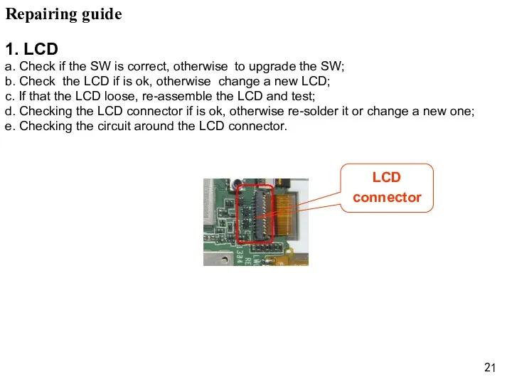
- 21. Repairing guide 1. LCD a. Check if the SW is correct, otherwise to upgrade the SW;
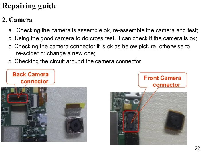
- 22. 2. Camera a. Checking the camera is assemble ok, re-assemble the camera and test; b. Using
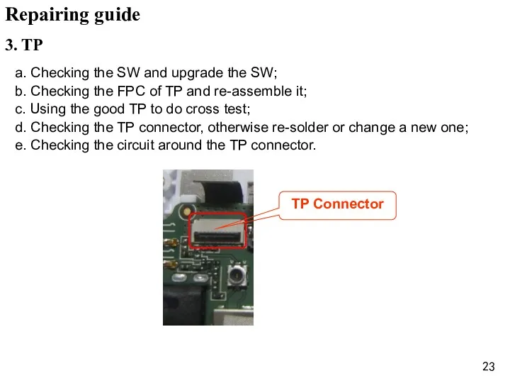
- 23. 3. TP a. Checking the SW and upgrade the SW; b. Checking the FPC of TP
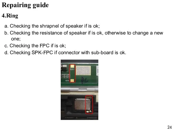
- 24. 4.Ring a. Checking the shrapnel of speaker if is ok; b. Checking the resistance of speaker
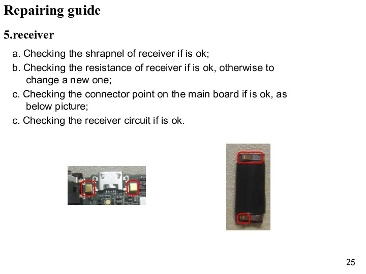
- 25. 5.receiver a. Checking the shrapnel of receiver if is ok; b. Checking the resistance of receiver
- 26. a. Checking the MIC and Vibrator is cold soldering, re-solder it; b. Change the MIC and
- 27. a. Checking the shrapnel of earphone if is ok; b. Checking the connector point on the
- 28. a. Checking the voltage of battery if is 3.8-4.2V and connect ok; b. Upgrade the SW;
- 29. a. Checking the voltage of battery if is over 3.4V; b. Checking the charger and USB
- 30. Checking the connector of T –card and SIM card; Change the connector of T –card and
- 31. a. Checking RF line if that is broken; b. Checking RF line assemble if is ok;
- 33. Скачать презентацию
content
1、 Product introduce..………..p3-p5
2、 Disassembly guide ……….p6-p20
3、 Repairing guide …………...p21-p31
content
1、 Product introduce..………..p3-p5
2、 Disassembly guide ……….p6-p20
3、 Repairing guide …………...p21-p31
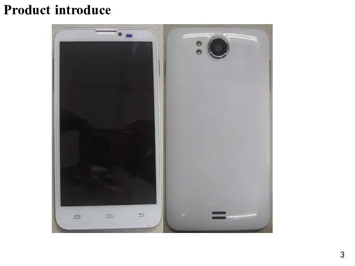
Product introduce
Product introduce
Product introduce
Model :
Product size: 147*77.2*9.9
Platform: Qualcomm MSM8225Q, Quad-Core 1.2GHz
Memory: 4GB+1GB (Nand&sdram+RAM)
System:
Product introduce
Model :
Product size: 147*77.2*9.9
Platform: Qualcomm MSM8225Q, Quad-Core 1.2GHz
Memory: 4GB+1GB (Nand&sdram+RAM)
System:
Hot gun
1. Tools list
Tweezer /Cross screw driver/ Solder/Tommy bar/hot gun
Disassembly
Hot gun
1. Tools list
Tweezer /Cross screw driver/ Solder/Tommy bar/hot gun
Disassembly
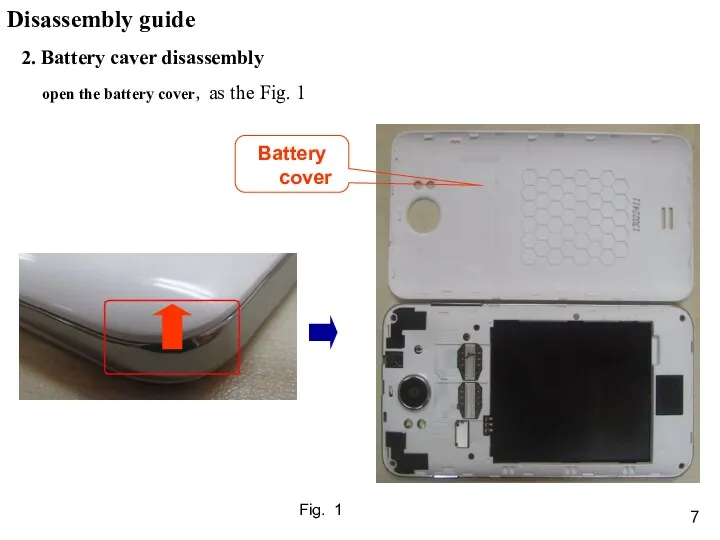
2. Battery caver disassembly
open the battery cover,as the Fig. 1
Fig. 1
Disassembly
2. Battery caver disassembly
open the battery cover,as the Fig. 1
Fig. 1
Disassembly
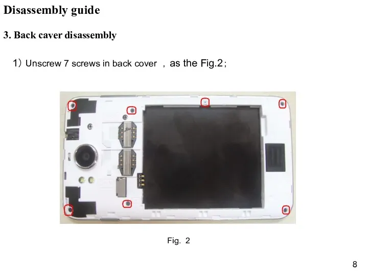
3. Back caver disassembly
1) Unscrew 7 screws in back cover ,as
3. Back caver disassembly
1) Unscrew 7 screws in back cover ,as
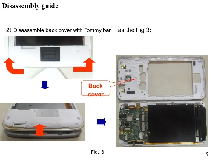
Fig. 3
2) Disassemble back cover with Tommy bar ,as the Fig.3;
Disassembly
Fig. 3
2) Disassemble back cover with Tommy bar ,as the Fig.3;
Disassembly
4.Main board and front cover disassembly
1)The main components of distribution,as
4.Main board and front cover disassembly
1)The main components of distribution,as
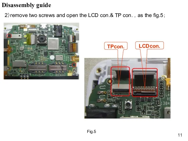
2)remove two screws and open the LCD con.& TP con.
2)remove two screws and open the LCD con.& TP con.
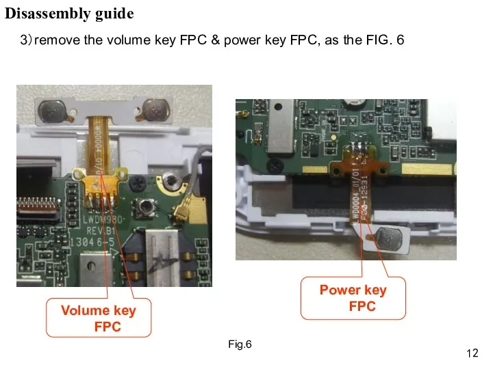
3)remove the volume key FPC & power key FPC, as
3)remove the volume key FPC & power key FPC, as
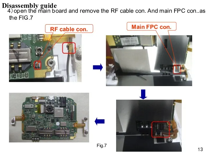
4)open the main board and remove the RF cable con.
4)open the main board and remove the RF cable con.
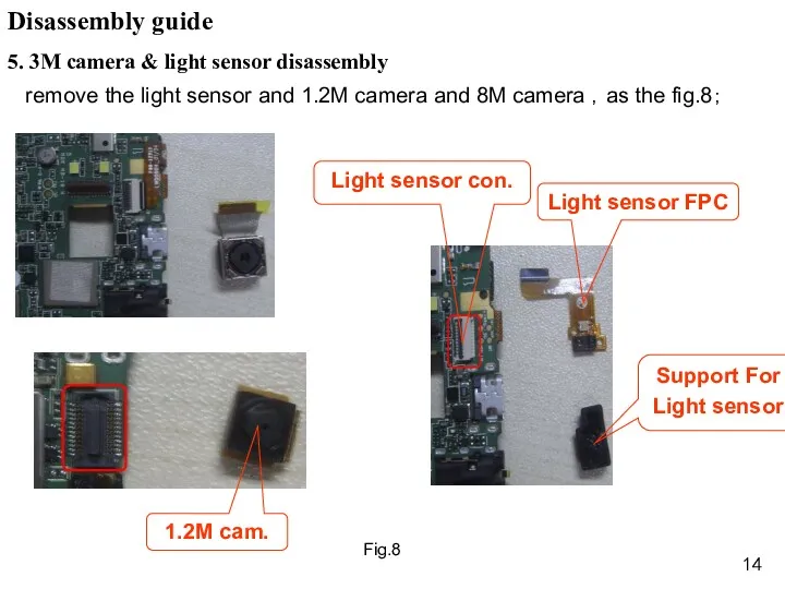
remove the light sensor and 1.2M camera and 8M camera
remove the light sensor and 1.2M camera and 8M camera
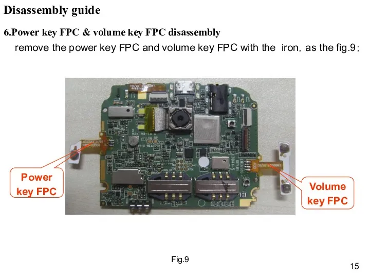
Fig.9
6.Power key FPC & volume key FPC disassembly
remove the power
Fig.9
6.Power key FPC & volume key FPC disassembly
remove the power
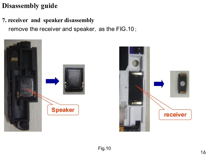
Fig.10
remove the receiver and speaker,as the FIG.10;
7. receiver and speaker
Fig.10
remove the receiver and speaker,as the FIG.10;
7. receiver and speaker
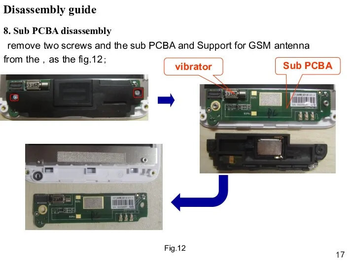
Fig.12
8. Sub PCBA disassembly
remove two screws and the sub PCBA
Fig.12
8. Sub PCBA disassembly
remove two screws and the sub PCBA
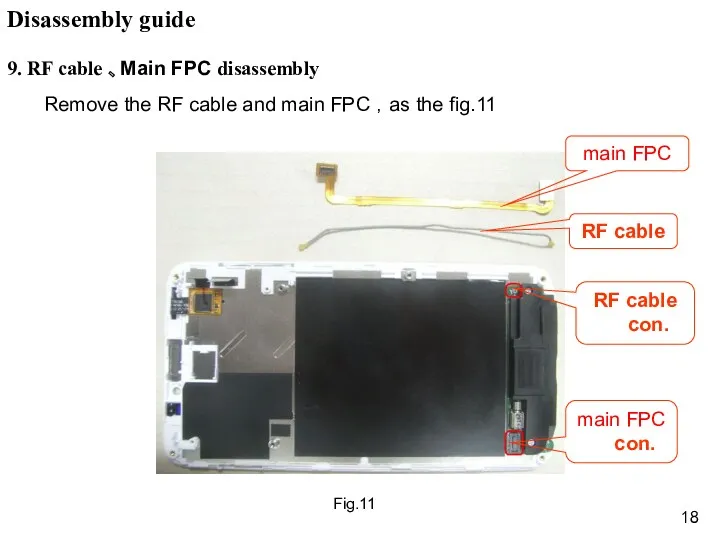
Fig.11
9. RF cable 、Main FPC disassembly
Remove the RF cable and main
Fig.11
9. RF cable 、Main FPC disassembly
Remove the RF cable and main
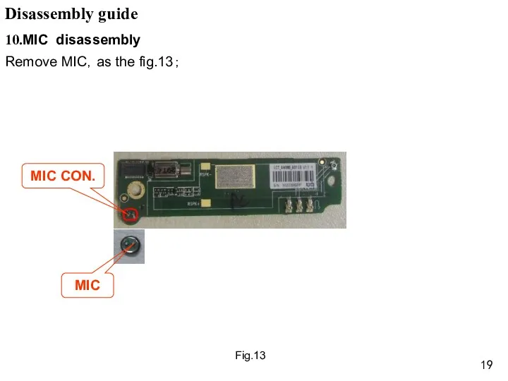
Fig.13
10.MIC disassembly
Remove MIC,as the fig.13;
Disassembly guide
MIC CON.
MIC
Fig.13
10.MIC disassembly
Remove MIC,as the fig.13;
Disassembly guide
MIC CON.
MIC
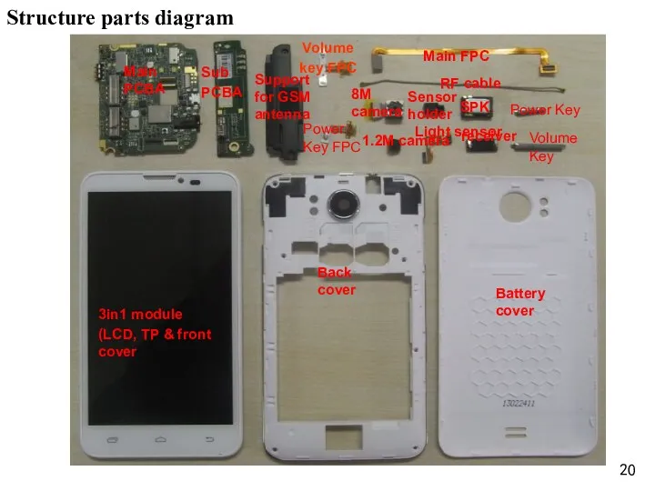
Structure parts diagram
3in1 module
(LCD, TP & front cover
Back cover
Battery cover
Main FPC
RF
Structure parts diagram
3in1 module
(LCD, TP & front cover
Back cover
Battery cover
Main FPC
RF
Repairing guide
1. LCD
a. Check if the SW is correct, otherwise to
Repairing guide
1. LCD
a. Check if the SW is correct, otherwise to
2. Camera
a. Checking the camera is assemble ok, re-assemble the camera
2. Camera
a. Checking the camera is assemble ok, re-assemble the camera
3. TP
a. Checking the SW and upgrade the SW;
b. Checking the
3. TP
a. Checking the SW and upgrade the SW;
b. Checking the
4.Ring
a. Checking the shrapnel of speaker if is ok;
b. Checking the
4.Ring
a. Checking the shrapnel of speaker if is ok;
b. Checking the
5.receiver
a. Checking the shrapnel of receiver if is ok;
b. Checking
5.receiver
a. Checking the shrapnel of receiver if is ok;
b. Checking
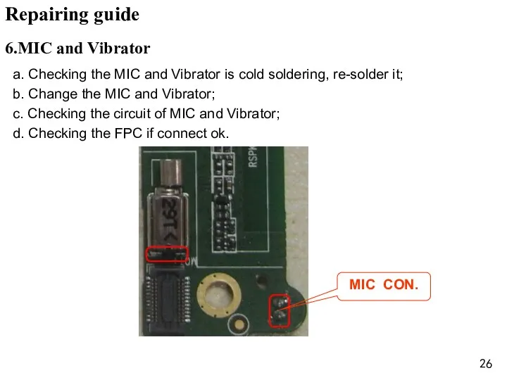
a. Checking the MIC and Vibrator is cold soldering, re-solder it;
b.
a. Checking the MIC and Vibrator is cold soldering, re-solder it;
b.
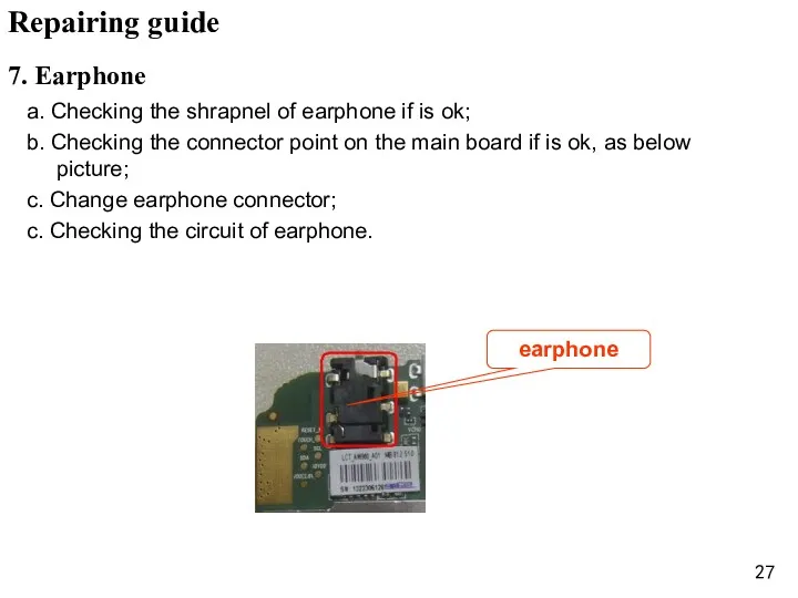
a. Checking the shrapnel of earphone if is ok;
b. Checking the
a. Checking the shrapnel of earphone if is ok;
b. Checking the
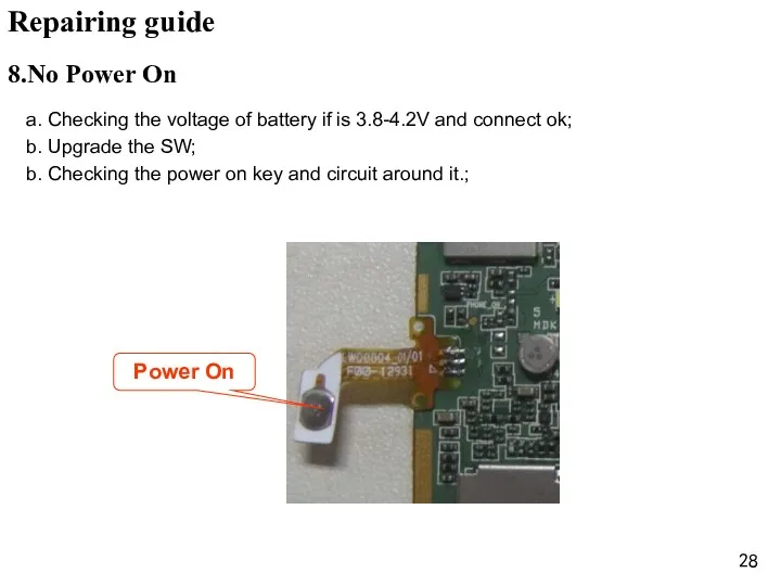
a. Checking the voltage of battery if is 3.8-4.2V and connect
a. Checking the voltage of battery if is 3.8-4.2V and connect
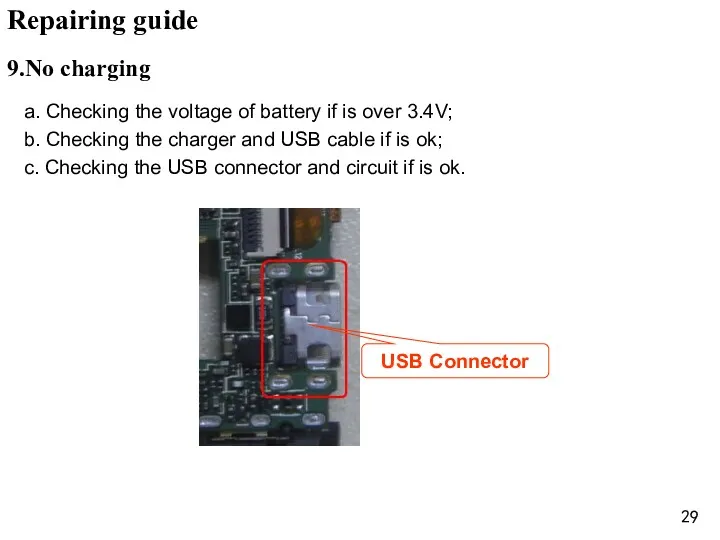
a. Checking the voltage of battery if is over 3.4V;
b. Checking
a. Checking the voltage of battery if is over 3.4V;
b. Checking
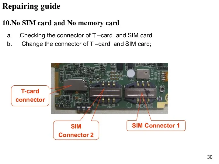
Checking the connector of T –card and SIM card;
Change the
Checking the connector of T –card and SIM card;
Change the
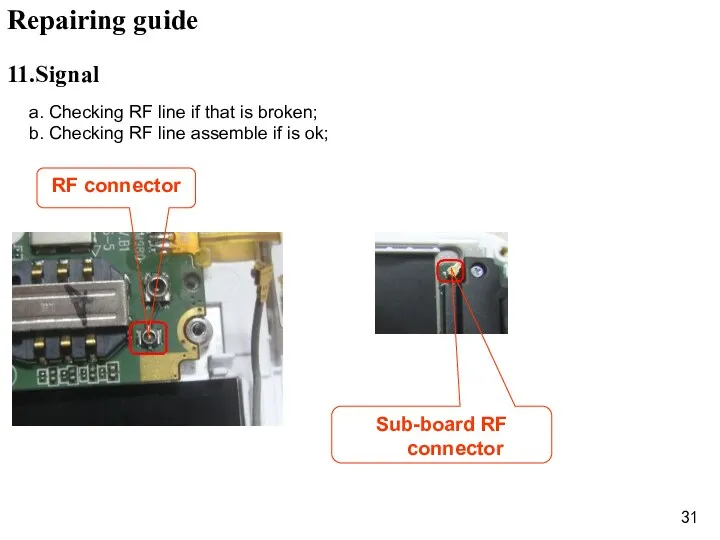
a. Checking RF line if that is broken;
b. Checking RF
a. Checking RF line if that is broken;
b. Checking RF
 Алкоголсіз сусындарды өндіруге арналған шикізат
 Основные фонды предприятия
 Англия в раннее Средневековье
 Автономные системы навигации летательных аппаратов
 Город Сокол. Бюджет для граждан на 2016 год
 Проект одномодельного технологічного потіку з виготовлення жакету жіночого з костюмних тканин
 Правила дорожного движения
 Бизнес-кейс Илона Маска
 презентация А. С. Пушкин 1 часть для начальной школы 3 класс
 Теория вероятностей и математическая статистика
 приглашение
 Всеобщая декларация прав человека - идеал права
 Технология разработки прогнозов разных уровней. Макроэкономическое прогнозирование
 Личная карта здоровья. Поставщики продукции Вивасан
 Мы за безопасность на дорогах
 Здравствуй, школа!
 Урок 105 Сложение однозначных чисел с переходом через десяток
 Кижи
Кижи Радиосвязное оборудование воздушных судов
 Клинический случай
 Ишемический инсульт
 Ветер
Ветер Строительство. Гигиенические требования к строительным материалам
 Этапы компьютерного моделирования
 Инженерно- геологические изыскания при строительстве тоннелей
 Урок по теме Добро и зло
 Православный этикет
 Взаимодествие детей и воспитателя в образовательной области Социально- коммуникативное развитие