- PAP5500DUO service manual

Содержание
- 2. content 1、 Product introduce..………..p3-p4 2、 Disassembly guide ……….p5-p17 3、Structure parts diagram…..p18 4、 Repairing guide …………...p19-p29
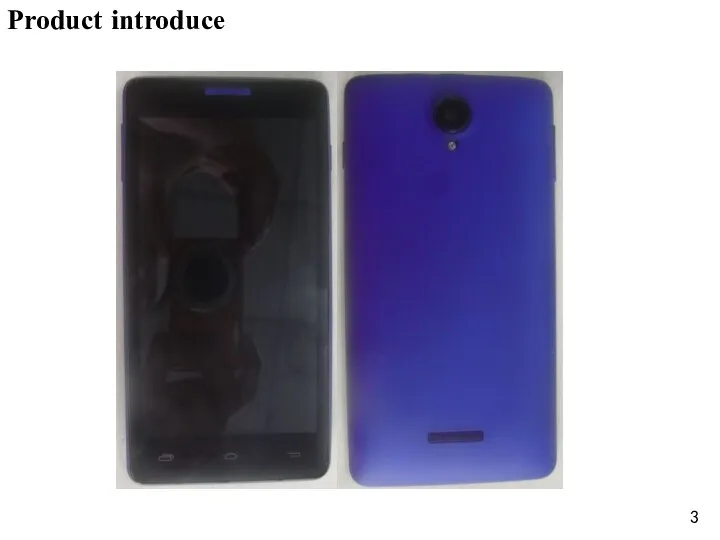
- 3. Product introduce
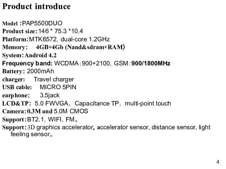
- 4. Product introduce Model :PAP5500DUO Product size:146 * 75.3 *10.4 Platform:MTK6572,dual-core 1.2GHz Memory: 4GB+4Gb (Nand&sdram+RAM) System:Android 4.2
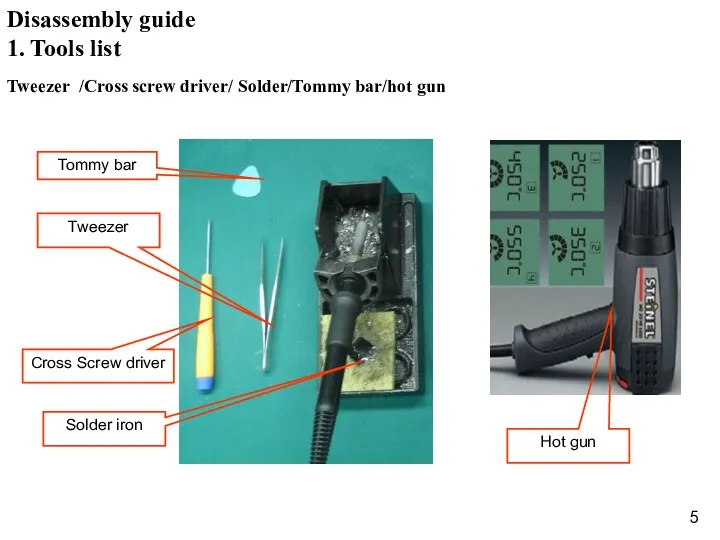
- 5. Hot gun 1. Tools list Tweezer /Cross screw driver/ Solder/Tommy bar/hot gun Disassembly guide
- 6. 2. Battery caver disassembly open the battery cover,as the Fig. 1 Fig. 1 Disassembly guide Battery
- 7. 3. Back caver disassembly 1) Unscrew 12 screws in back cover ,as the Fig.2; Fig. 2
- 8. Fig. 3 2) Disassemble back cover with Tommy bar ,as the Fig.3; Disassembly guide Back cover
- 9. 4.Main board and front cover disassembly 1)The main components of distribution,as the fig.4; Fig.4 Disassembly guide
- 10. 2)remove two screws and open the LCD con.& TP con. ,and remove the volume key FPC
- 11. 3)open the main board and remove the RF cable con. And main FPC con..as the FIG.6
- 12. remove the light sensor and camera,as the fig.7; 5. Front and Back camera & light sensor
- 13. Fig.8 6.Power key FPC & volume key FPC disassembly remove the power key FPC and volume
- 14. Fig.9 remove the Speaker camera and receiver,as the FIG.9; 7. Speaker & receiver disassembly Disassembly guide
- 15. Fig.10 8. RF cable and Main FPC disassembly Remove the RF cable and Main FPC ,as
- 16. Fig.11 9. Sub PCBA disassembly remove the sub PCBA from the ,as the fig.11; Disassembly guide
- 17. Fig.12 10.MIC disassembly Remove the MIC,as the fig.12; Disassembly guide MIC con.
- 18. Structure parts diagram Battery cover Back cover 3in1 module (LCD, TP & front cover RF cable
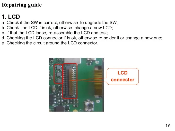
- 19. Repairing guide 1. LCD a. Check if the SW is correct, otherwise to upgrade the SW;
- 20. 2. Camera a. Checking the camera is assemble ok, re-assemble the camera and test; b. Using
- 21. 3. TP a. Checking the SW and upgrade the SW; b. Checking the FPC of TP
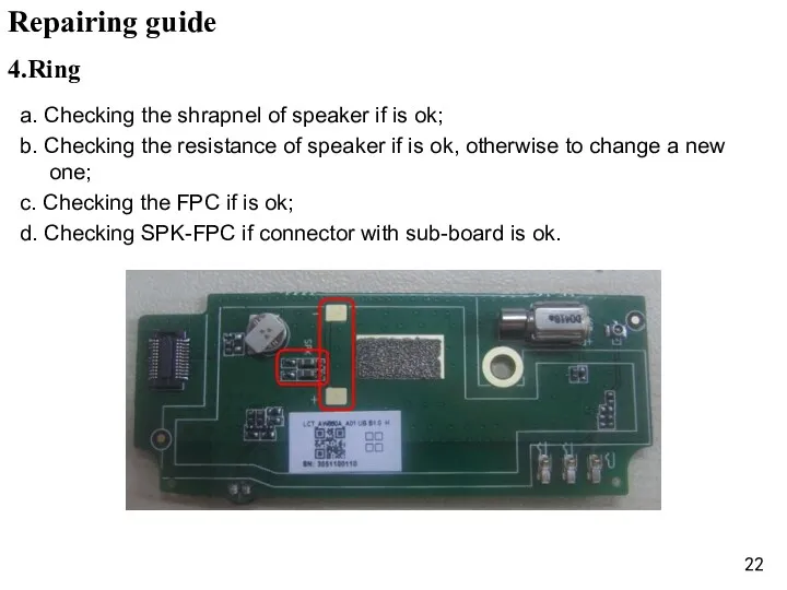
- 22. 4.Ring a. Checking the shrapnel of speaker if is ok; b. Checking the resistance of speaker
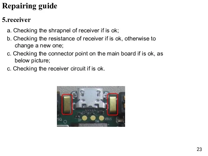
- 23. 5.receiver a. Checking the shrapnel of receiver if is ok; b. Checking the resistance of receiver
- 24. a. Checking the MIC and Vibrator is cold soldering, re-solder it; b. Change the MIC and
- 25. a. Checking the shrapnel of earphone if is ok; b. Checking the connector point on the
- 26. a. Checking the voltage of battery if is 3.8-4.2V and connect ok; b. Upgrade the SW;
- 27. a. Checking the voltage of battery if is over 3.4V; b. Checking the charger and USB
- 28. Checking the connector of T –card and SIM card; Change the connector of T –card and
- 30. Скачать презентацию
content
1、 Product introduce..………..p3-p4
2、 Disassembly guide ……….p5-p17
3、Structure parts diagram…..p18
content
1、 Product introduce..………..p3-p4
2、 Disassembly guide ……….p5-p17
3、Structure parts diagram…..p18
Product introduce
Product introduce
Product introduce
Model :PAP5500DUO
Product size:146 * 75.3 *10.4
Platform:MTK6572,dual-core 1.2GHz
Memory: 4GB+4Gb (Nand&sdram+RAM)
System:Android 4.2
Frequency
Product introduce
Model :PAP5500DUO
Product size:146 * 75.3 *10.4
Platform:MTK6572,dual-core 1.2GHz
Memory: 4GB+4Gb (Nand&sdram+RAM)
System:Android 4.2
Frequency
Hot gun
1. Tools list
Tweezer /Cross screw driver/ Solder/Tommy bar/hot gun
Disassembly
Hot gun
1. Tools list
Tweezer /Cross screw driver/ Solder/Tommy bar/hot gun
Disassembly
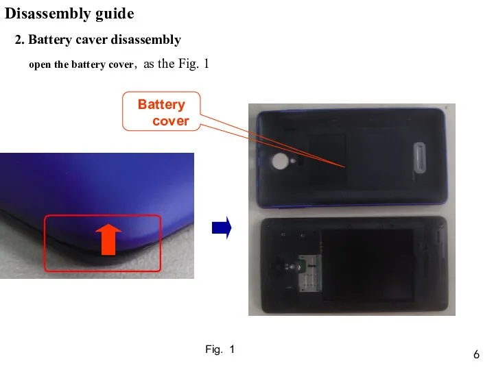
2. Battery caver disassembly
open the battery cover,as the Fig. 1
Fig. 1
Disassembly
2. Battery caver disassembly
open the battery cover,as the Fig. 1
Fig. 1
Disassembly
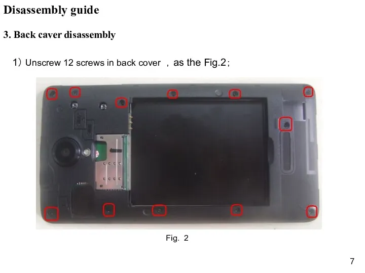
3. Back caver disassembly
1) Unscrew 12 screws in back cover ,as
3. Back caver disassembly
1) Unscrew 12 screws in back cover ,as
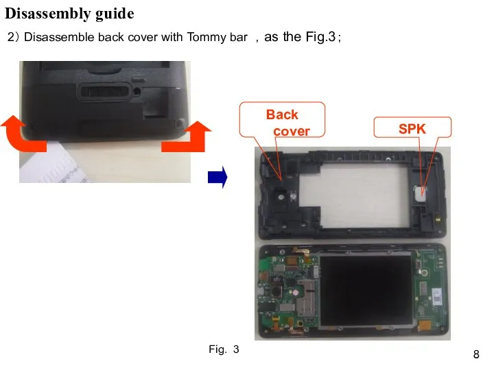
Fig. 3
2) Disassemble back cover with Tommy bar ,as the Fig.3;
Disassembly
Fig. 3
2) Disassemble back cover with Tommy bar ,as the Fig.3;
Disassembly
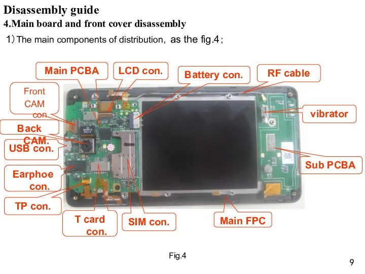
4.Main board and front cover disassembly
1)The main components of distribution,as
4.Main board and front cover disassembly
1)The main components of distribution,as
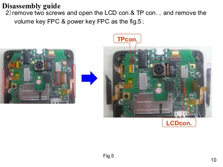
2)remove two screws and open the LCD con.& TP con.
2)remove two screws and open the LCD con.& TP con.
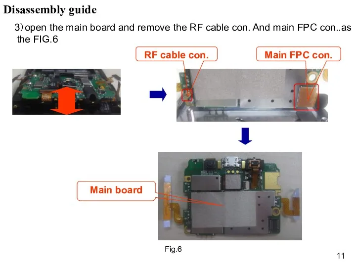
3)open the main board and remove the RF cable con.
3)open the main board and remove the RF cable con.
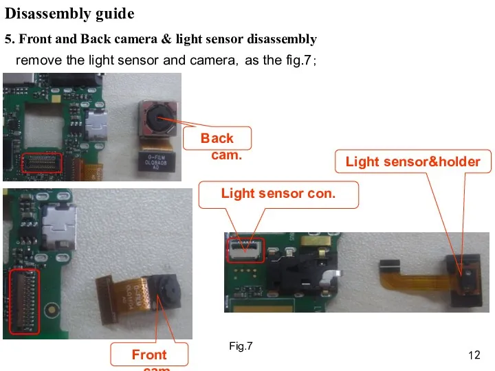
remove the light sensor and camera,as the fig.7;
5. Front and
remove the light sensor and camera,as the fig.7;
5. Front and
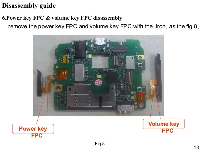
Fig.8
6.Power key FPC & volume key FPC disassembly
remove the power
Fig.8
6.Power key FPC & volume key FPC disassembly
remove the power
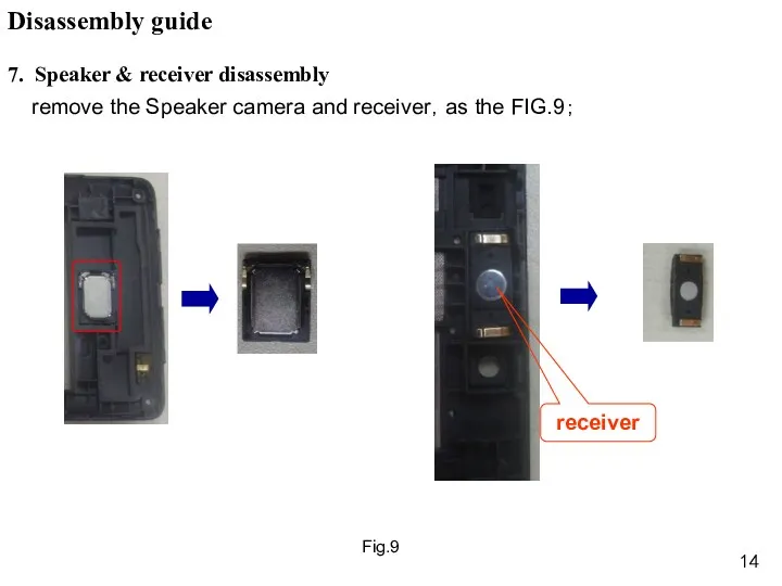
Fig.9
remove the Speaker camera and receiver,as the FIG.9;
7. Speaker &
Fig.9
remove the Speaker camera and receiver,as the FIG.9;
7. Speaker &
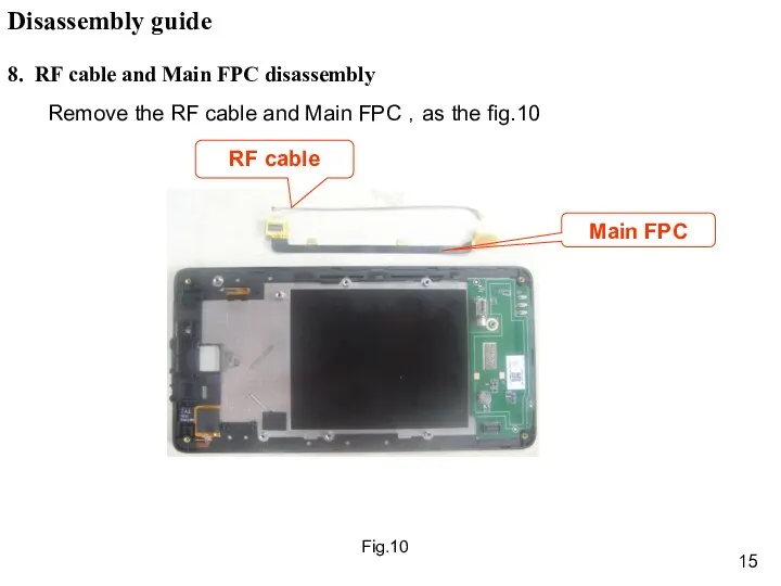
Fig.10
8. RF cable and Main FPC disassembly
Remove the RF cable and
Fig.10
8. RF cable and Main FPC disassembly
Remove the RF cable and
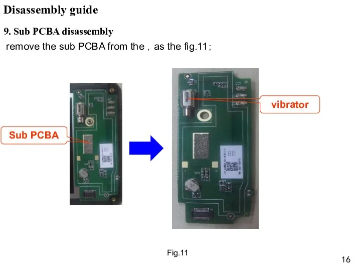
Fig.11
9. Sub PCBA disassembly
remove the sub PCBA from the ,as
Fig.11
9. Sub PCBA disassembly
remove the sub PCBA from the ,as
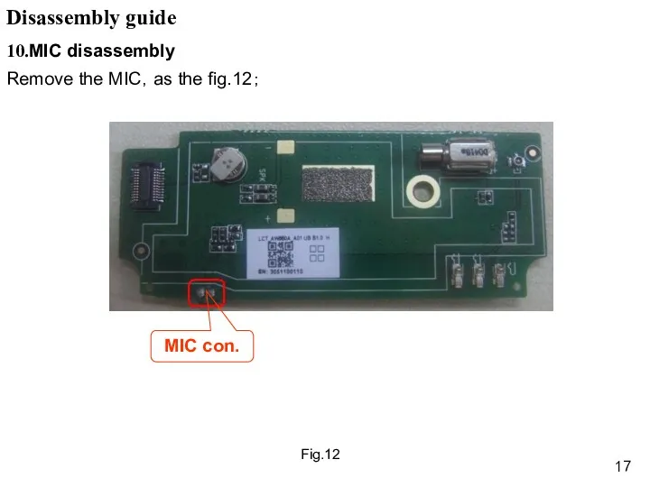
Fig.12
10.MIC disassembly
Remove the MIC,as the fig.12;
Disassembly guide
MIC con.
Fig.12
10.MIC disassembly
Remove the MIC,as the fig.12;
Disassembly guide
MIC con.
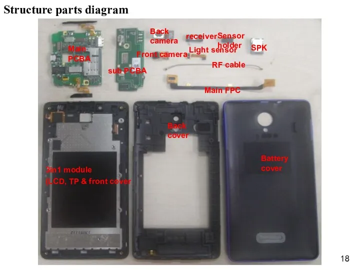
Structure parts diagram
Battery cover
Back cover
3in1 module
(LCD, TP & front cover
RF cable
SPK
Back
Structure parts diagram
Battery cover
Back cover
3in1 module
(LCD, TP & front cover
RF cable
SPK
Back
Repairing guide
1. LCD
a. Check if the SW is correct, otherwise to
Repairing guide
1. LCD
a. Check if the SW is correct, otherwise to
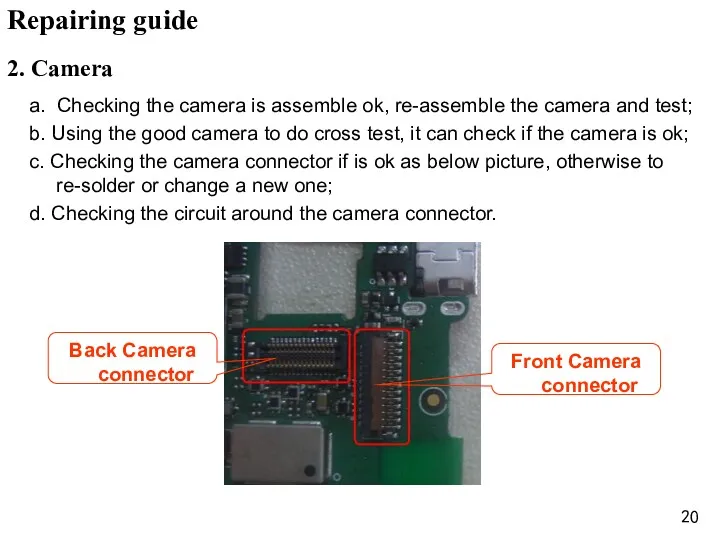
2. Camera
a. Checking the camera is assemble ok, re-assemble the camera
2. Camera
a. Checking the camera is assemble ok, re-assemble the camera
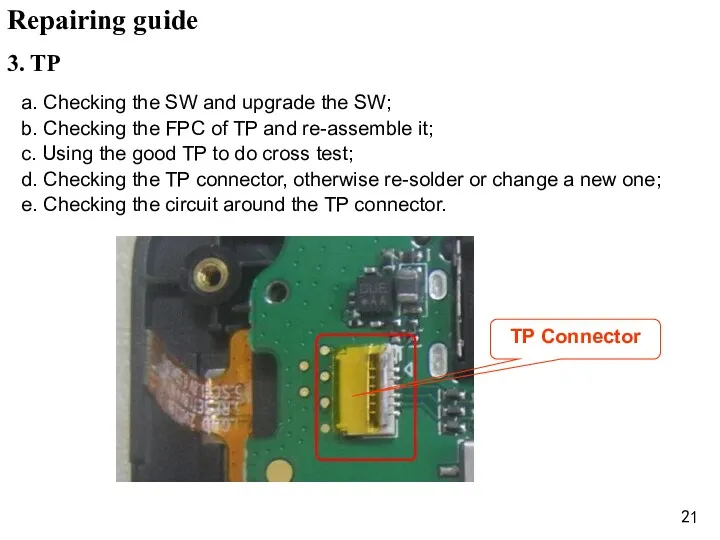
3. TP
a. Checking the SW and upgrade the SW;
b. Checking the
3. TP
a. Checking the SW and upgrade the SW;
b. Checking the
4.Ring
a. Checking the shrapnel of speaker if is ok;
b. Checking the
4.Ring
a. Checking the shrapnel of speaker if is ok;
b. Checking the
5.receiver
a. Checking the shrapnel of receiver if is ok;
b. Checking
5.receiver
a. Checking the shrapnel of receiver if is ok;
b. Checking
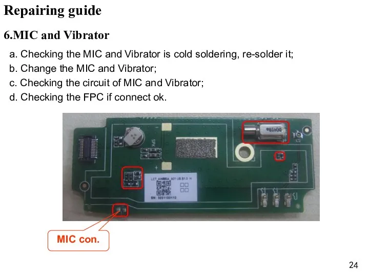
a. Checking the MIC and Vibrator is cold soldering, re-solder it;
b.
a. Checking the MIC and Vibrator is cold soldering, re-solder it;
b.
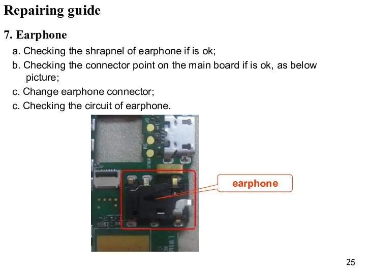
a. Checking the shrapnel of earphone if is ok;
b. Checking the
a. Checking the shrapnel of earphone if is ok;
b. Checking the
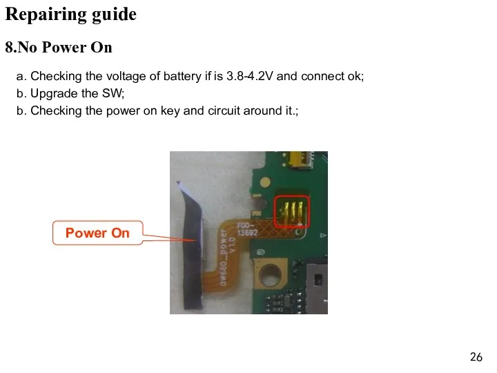
a. Checking the voltage of battery if is 3.8-4.2V and connect
a. Checking the voltage of battery if is 3.8-4.2V and connect
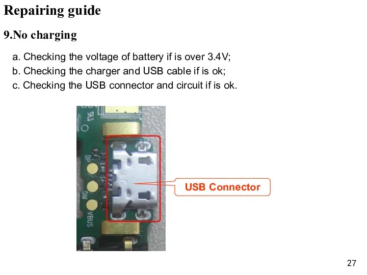
a. Checking the voltage of battery if is over 3.4V;
b. Checking
a. Checking the voltage of battery if is over 3.4V;
b. Checking
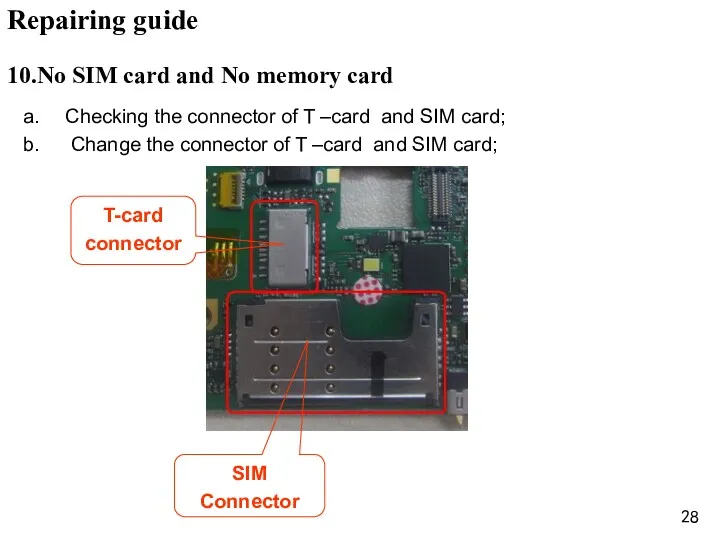
Checking the connector of T –card and SIM card;
Change the
Checking the connector of T –card and SIM card;
Change the
 Премедикация
 Порядок заключения трудового договора. Изменение трудового договора
 Проект Любимые игрушки
 Организация мультимодальных пассажирских перевозок
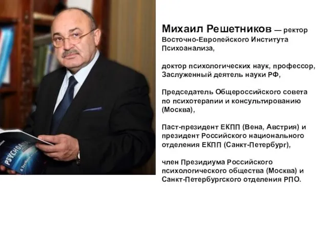 ИМАТОН. Саммит психологов России 2013
 Сказка Теремок Бианки
 Личностные качества юриста
 Электронное портфолио Я - учитель
 Изготовление новогодних ёлок из подручных материалов
 Лишь вера одна никогда не бывает одна
 Пять основных принципов влияния родителей на ребенка
 Туберкулез. Особенности возбудителя туберкулеза
 Александр Александрович Фадеев 1901 - 1956
 Элективный курс как средство профильного обучения на старшей ступени полного (среднего) образования
 Библиотечно-библиографическая классификация
 Михаил Михайлович Пришвин. Сказка-быль Кладовая солнца
 Правописание гласных в падежных окончаниях прилагательных
 Фигура человека в движении. Этапы рисования
 Разработка модели развития дефекта на границе раздела фаз в стеклопластике на основе термопластичной матрицы
 Внедрение инновационных технологий воспитания в условиях перехода в ФГОС.
 Архитектура параллельных вычислительных систем. Часть 2. Классификация ПВС
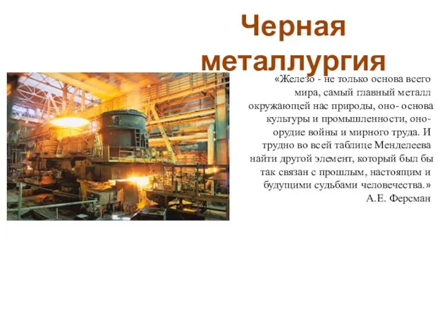 Черная металлургия
 Дети и театр
 Православная молитва. Проект урока
 презентация Развитие социального интеллекта у детей дошкольного возраста в игровой деятельости Диск
 Интерфейс проекта. (7 класс)
 Эмоции и мимика
 Вода и здоровье населения. Гигиенические аспекты водоснабжения населённых мест