- Power Wave® S350 CE & STT Module Service Training

Содержание
- 4. S350CE On/Off Switch 4 pin Work Sense Fault LED Thermal LED No optional UI kit “+”
- 5. S350CE G6682 Control Board CE Filter
- 6. S350CE Not Used Circuit Breaker Sync Tandem STT Connector, part of STT module EtherNET Line Cord
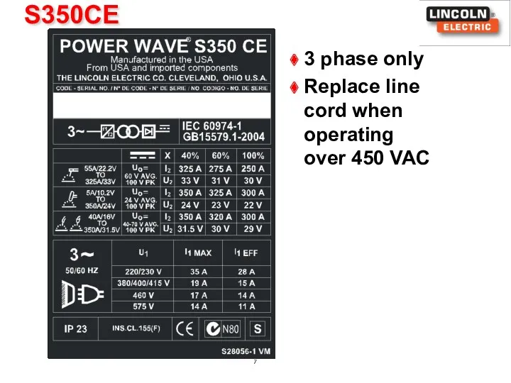
- 7. S350CE 3 phase only Replace line cord when operating over 450 VAC
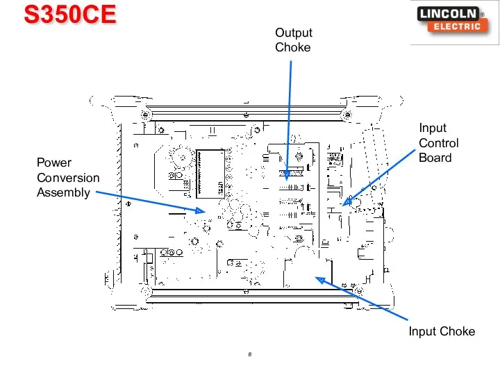
- 8. S350CE Input Choke Output Choke Input Control Board Power Conversion Assembly
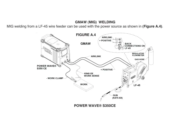
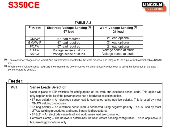
- 13. S350CE Feeder:
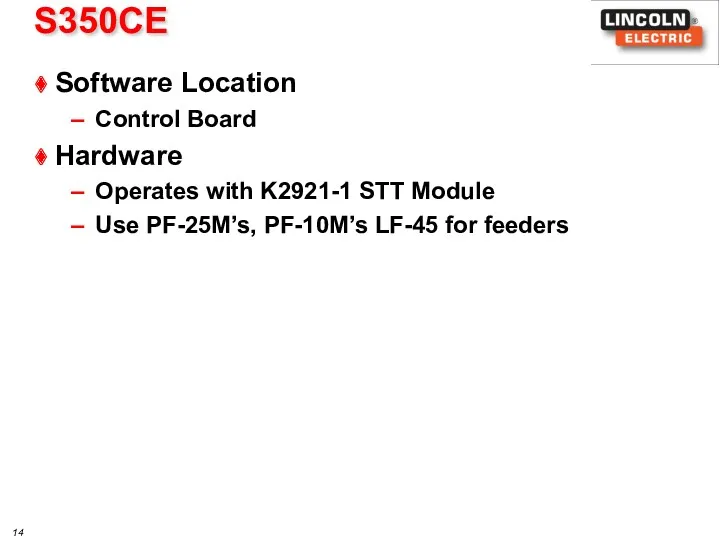
- 14. S350CE Software Location Control Board Hardware Operates with K2921-1 STT Module Use PF-25M’s, PF-10M’s LF-45 for
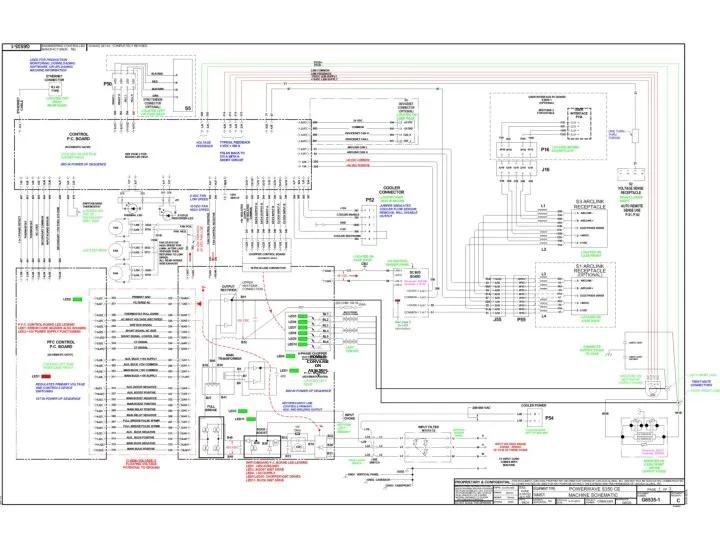
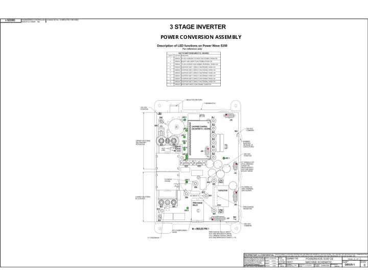
- 15. POWER CONVERSION ASSEMPLY
- 17. POWER CONVERSION ASSEMBLY
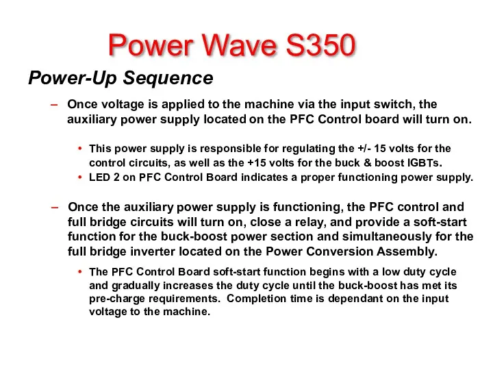
- 18. Power Wave S350 Power-Up Sequence Once voltage is applied to the machine via the input switch,
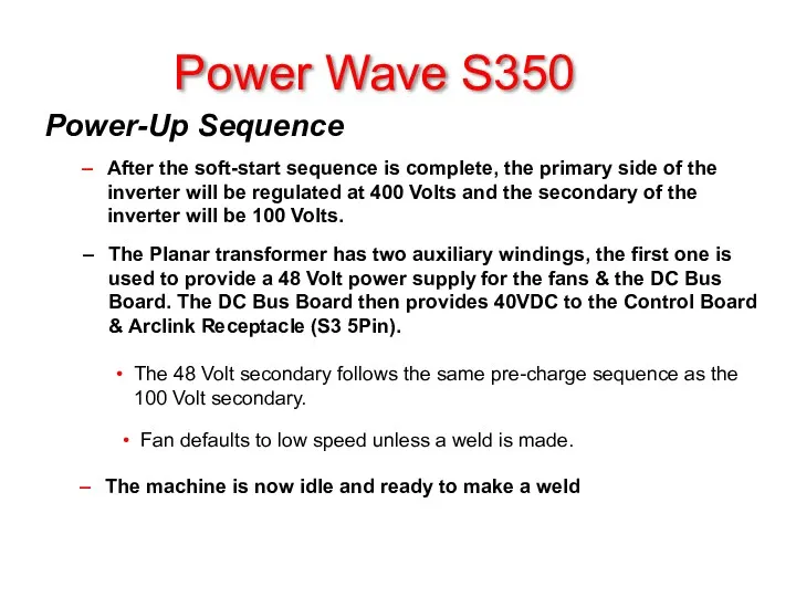
- 19. Power Wave S350 Power-Up Sequence After the soft-start sequence is complete, the primary side of the
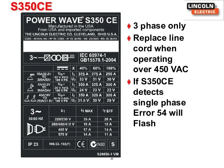
- 20. S350CE 3 phase only Replace line cord when operating over 450 VAC If S350CE detects single
- 21. Analog and Digital circuits control the current shaping, regulated bus voltage, and gate drive signals for
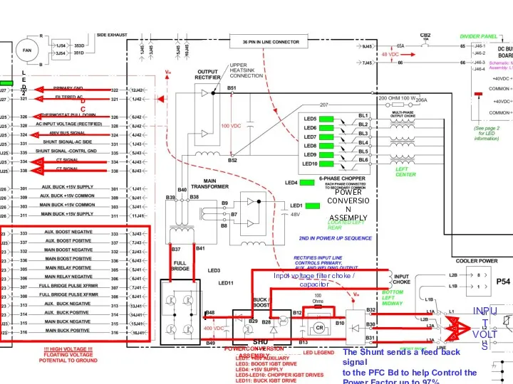
- 22. SHUNT The Shunt sends a feed back signal to the PFC Bd to help Control the
- 23. Buck/Boost Theory of Operation Depending upon the input line voltage, the PFC Control PC Board will
- 24. Thermostat Signal to Control Board
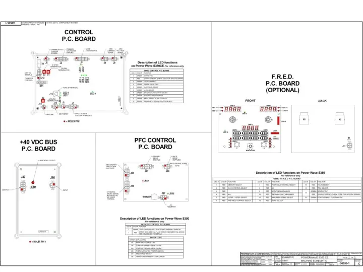
- 25. Pause between sounds/flashes indicating a specific digit: 0.5 seconds Buzzer Error Codes PFC Control Board (G5915
- 26. PFC Control Board (G5915 series) Auxiliary Power Supply and PFC Circuits HIGH VOLTAGE AUXILIARY POWER SUPPY
- 27. PFC CONTROL BOARD Use DVM Diode check function from 8J42 to 1J42 Auxiliary Power Supply Failure
- 28. First Stage Function Detects thermal trips that may occur on the first stage heatsink (single thermostat
- 29. Primary Thermal Protection Location: SMT Part, First and Second Stage Module (M21214-10) Function Primary Thermal Circuit
- 30. Relay and DC Link Capacitor 3-phase input rectifier converts AC line voltage to DC Perform diode
- 31. Power Conversion Assembly First Stage – Buck Boost
- 32. Second Stage Functions Converts rectified 400 Volts dc input to an unregulated 100 Volts dc output
- 33. Planar Transformer Design Features Printed circuit board Individually sealed Small footprint allows for mounting directly onto
- 34. Functions Multi-Phase Chopper Used to control welding Voltage and Current 100 Volt DC input with regulated
- 35. SHUNT 48VDC 48VDC HIGH 24VDC LOW 100VDC 48VDC FAN ALWAYS ON LOW OR HIGH 322 to
- 36. Implementation Multi-Phase Chopper + 48 Volt dc auxiliary power supply indicator LED1 Six LEDs are used
- 37. Functions Control PC Board Serves as the main communication interface ArcLink master Ethernet Controls the Chopper
- 38. Data Input to IGBTs & Supply Voltage 40VDC From Bus BD Low & High Speed Fan
- 39. Secondary Thermostat Status LED On Front Thermostat LED On Front This is where The STT Differential
- 40. Thermal Protection Function Secondary Thermal Circuit Protects machine against reduced airflow or overload. Fan ON /
- 41. Simplified Test Procedure Current Transducer (S18504-6) Verify 30 VDC present at supply leads Check the feedback
- 42. “Must Have” LED’s 10 DeviceNet Power Status LED’s Control PC Board DIP Switches – Factory Default
- 43. ERROE CODES POWER WAVE S350
- 44. STT Module Service Training K2921-1
- 47. STT Module Front View Rear View
- 48. STT Module Typical Mounting
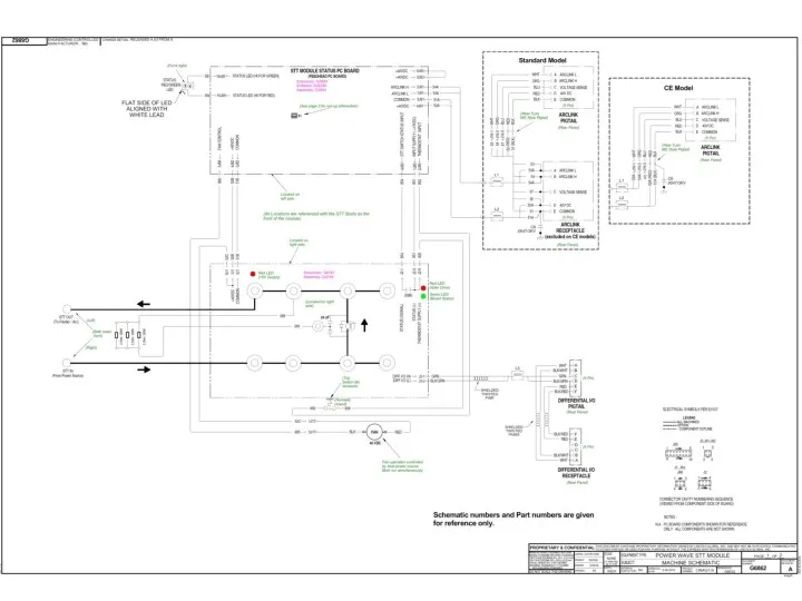
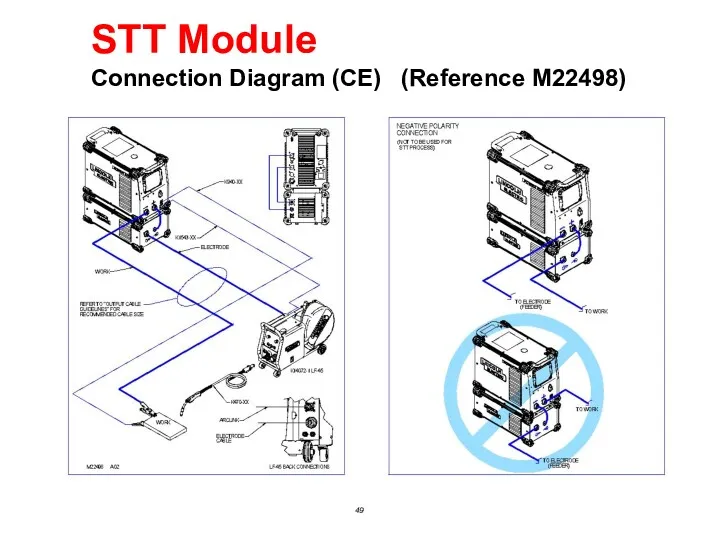
- 49. STT Module Connection Diagram (CE) (Reference M22498)
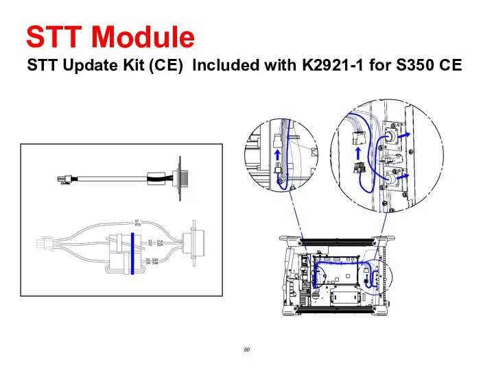
- 50. STT Module STT Update Kit (CE) Included with K2921-1 for S350 CE
- 51. STT - The Basics STT Module Typical shorting frequency ≅ 100 - 120Hz
- 52. STT Module Component Location
- 53. Functions STT Status PC Board (S28250/G3884 series) Identifies STT Module to ArcLink Network Receives Switch PCB
- 54. 40VDC IN 40VDC out To STT Switch Board Arclink Thermostat 851-852 Closed Open >10VDC Arclink 40VDC
- 55. STT Status PC Board (S28250/G3884 series)
- 56. Troubleshooting with External LED STT Status PC Board (S28250/G3884 series) No LED Check LED placement and
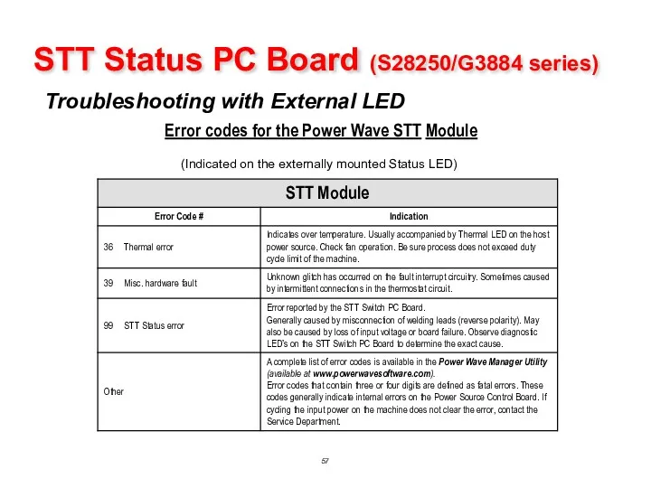
- 57. STT Status PC Board (S28250/G3884 series) Troubleshooting with External LED Error codes for the Power Wave
- 58. Troubleshooting Input and Output Circuits STT Status PC Board (S28250/G3884 series) Thermostat Input Best Measured across
- 59. Functions STT Switch PC Board (G6768 series) Interrupts Power Source Output Current Includes integral snubber diodes
- 60. 40VDC Input LED 3 15VDC In To STT Module Switch Status input Thermostat 851-852 Closed Open
- 61. STT Switch PC Board (G6768 series)
- 62. STT Switch PC Board (G6768 series) Functional Block Diagram
- 63. STT Switch PC Board (G6768 series) Gate Drive Signal (RS-485 Differential signal from Power Source)
- 64. STT Switch PC Board (G6768 series) Snubber Configuration Capacitor Absorbs initial energy Resistor Limits maximum voltage
- 66. Скачать презентацию

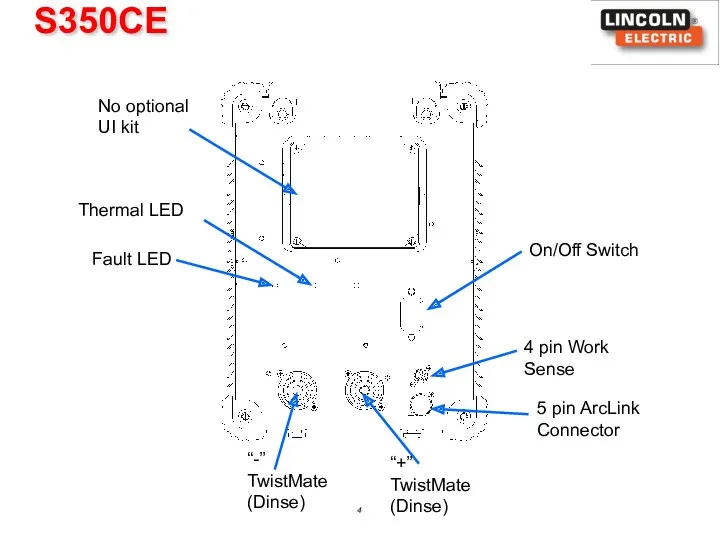
S350CE
On/Off Switch
4 pin Work Sense
Fault LED
Thermal LED
No optional UI kit
“+”
TwistMate (Dinse)
“-”
TwistMate
S350CE
On/Off Switch
4 pin Work Sense
Fault LED
Thermal LED
No optional UI kit
“+”
TwistMate (Dinse)
“-”
TwistMate
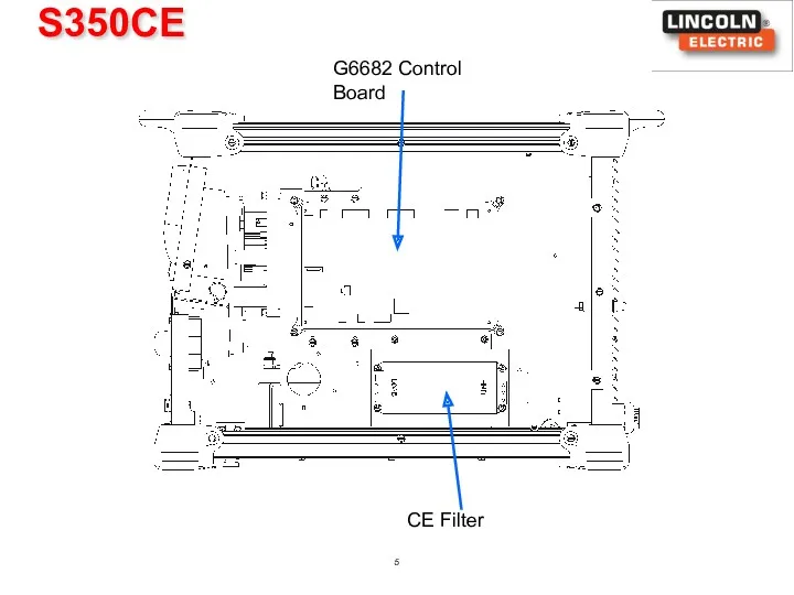
S350CE
G6682 Control Board
CE Filter
S350CE
G6682 Control Board
CE Filter
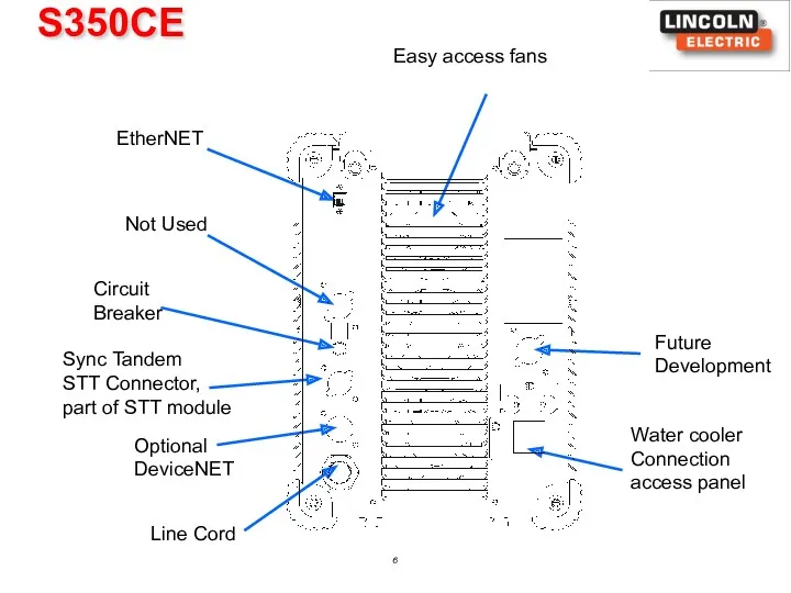
S350CE
Not Used
Circuit
Breaker
Sync Tandem
STT Connector, part of STT module
EtherNET
Line Cord
Optional
DeviceNET
Water cooler
Connection access
S350CE
Not Used
Circuit
Breaker
Sync Tandem
STT Connector, part of STT module
EtherNET
Line Cord
Optional
DeviceNET
Water cooler
Connection access
S350CE
3 phase only
Replace line cord when operating over 450 VAC
S350CE
3 phase only
Replace line cord when operating over 450 VAC
S350CE
Input Choke
Output Choke
Input Control Board
Power Conversion Assembly
S350CE
Input Choke
Output Choke
Input Control Board
Power Conversion Assembly
S350CE
Feeder:
S350CE
Feeder:
S350CE
Software Location
Control Board
Hardware
Operates with K2921-1 STT Module
Use PF-25M’s, PF-10M’s LF-45
S350CE
Software Location
Control Board
Hardware
Operates with K2921-1 STT Module
Use PF-25M’s, PF-10M’s LF-45
POWER
CONVERSION
ASSEMPLY
POWER
CONVERSION
ASSEMPLY
POWER CONVERSION ASSEMBLY
POWER CONVERSION ASSEMBLY
Power Wave S350
Power-Up Sequence
Once voltage is applied to the machine via
Power Wave S350
Power-Up Sequence
Once voltage is applied to the machine via
Power Wave S350
Power-Up Sequence
After the soft-start sequence is complete, the primary
Power Wave S350
Power-Up Sequence
After the soft-start sequence is complete, the primary
S350CE
3 phase only
Replace line cord when operating over 450 VAC
If S350CE
S350CE
3 phase only
Replace line cord when operating over 450 VAC
If S350CE
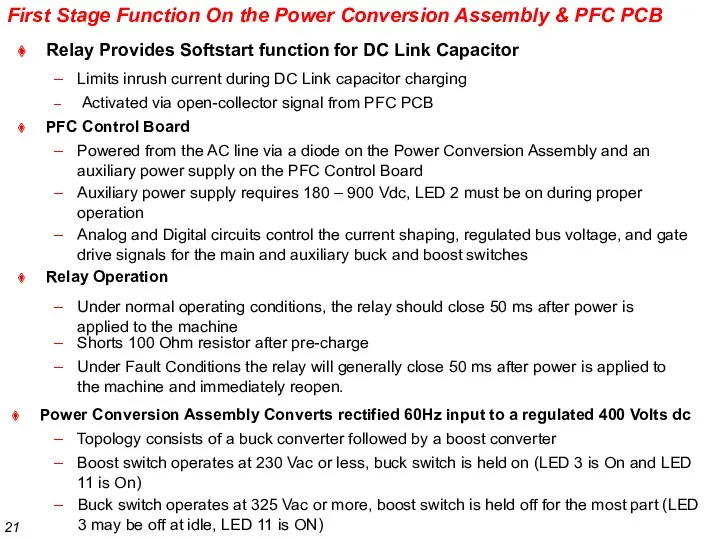
Analog and Digital circuits control the current shaping, regulated bus voltage,
Analog and Digital circuits control the current shaping, regulated bus voltage,
SHUNT
The Shunt sends a feed back signal
to the PFC Bd to
SHUNT
The Shunt sends a feed back signal
to the PFC Bd to
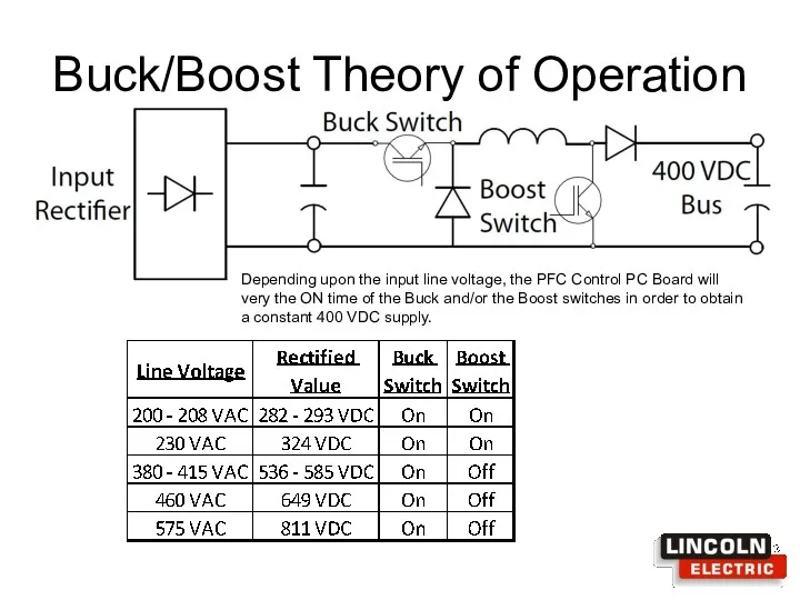
Buck/Boost Theory of Operation
Depending upon the input line voltage, the PFC
Buck/Boost Theory of Operation
Depending upon the input line voltage, the PFC
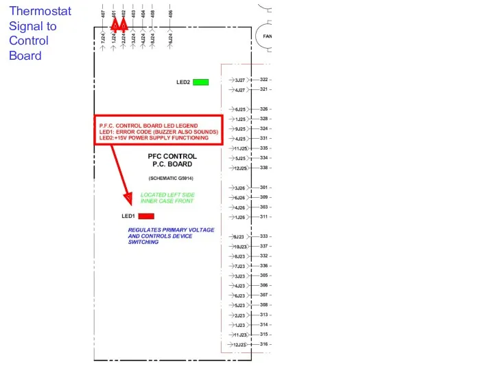
Thermostat
Signal to
Control Board
Thermostat
Signal to
Control Board
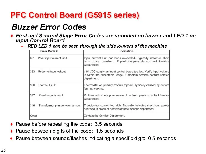
Pause between sounds/flashes indicating a specific digit: 0.5 seconds
Buzzer Error Codes
PFC
Pause between sounds/flashes indicating a specific digit: 0.5 seconds
Buzzer Error Codes
PFC
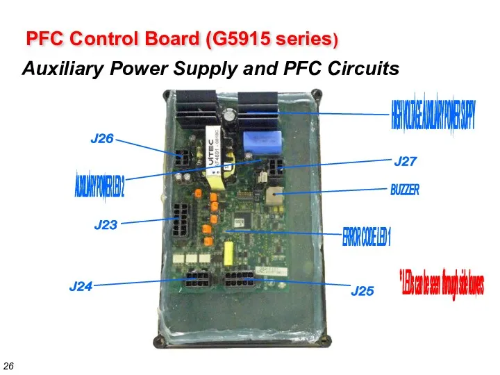
PFC Control Board (G5915 series)
Auxiliary Power Supply and PFC Circuits
HIGH VOLTAGE
PFC Control Board (G5915 series)
Auxiliary Power Supply and PFC Circuits
HIGH VOLTAGE
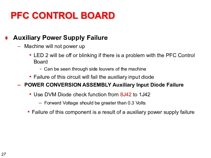
PFC CONTROL BOARD
Use DVM Diode check function from 8J42 to 1J42
Auxiliary
PFC CONTROL BOARD
Use DVM Diode check function from 8J42 to 1J42
Auxiliary
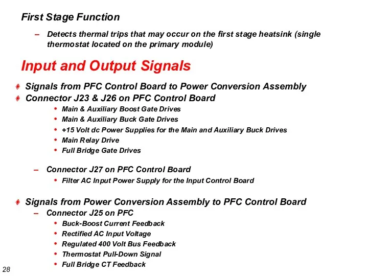
First Stage Function
Detects thermal trips that may occur on the first
First Stage Function
Detects thermal trips that may occur on the first

Primary Thermal Protection
Location:
SMT Part, First and Second Stage Module (M21214-10)
Function
Primary
Primary Thermal Protection
Location:
SMT Part, First and Second Stage Module (M21214-10)
Function
Primary
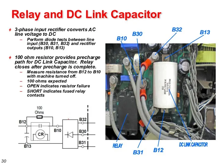
Relay and DC Link Capacitor
3-phase input rectifier converts AC line voltage
Relay and DC Link Capacitor
3-phase input rectifier converts AC line voltage
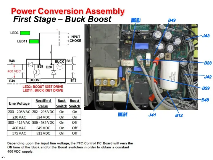
Power Conversion Assembly
First Stage – Buck Boost
Power Conversion Assembly
First Stage – Buck Boost
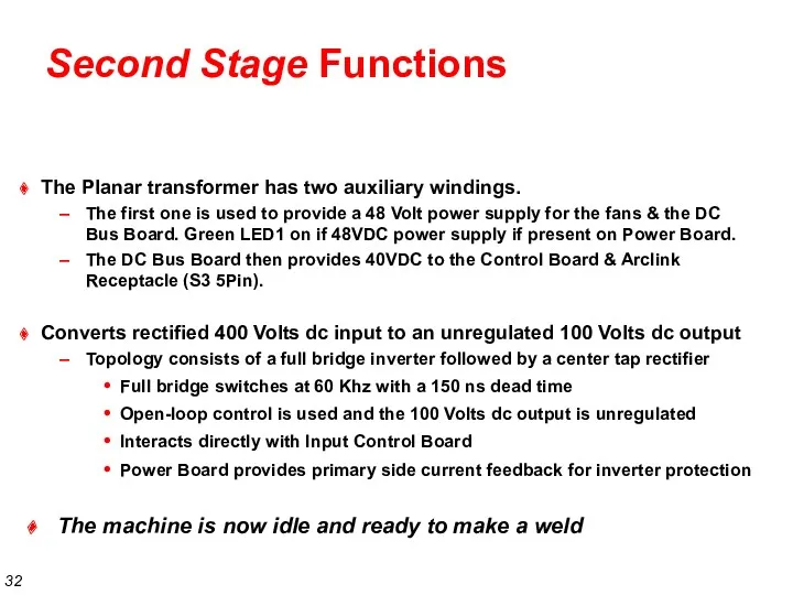
Second Stage Functions
Converts rectified 400 Volts dc input to an unregulated
Second Stage Functions
Converts rectified 400 Volts dc input to an unregulated
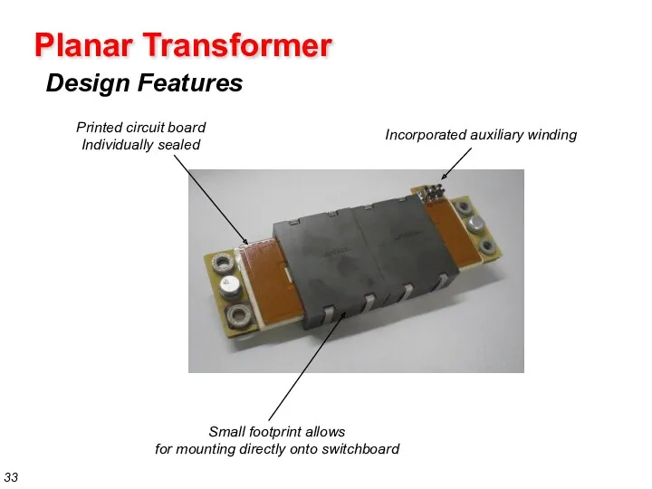
Planar Transformer
Design Features
Printed circuit board
Individually sealed
Small footprint allows
for mounting directly onto
Planar Transformer
Design Features
Printed circuit board
Individually sealed
Small footprint allows
for mounting directly onto
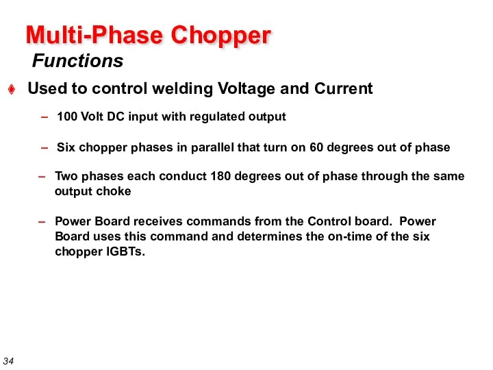
Functions
Multi-Phase Chopper
Used to control welding Voltage and Current
100 Volt DC input
Functions
Multi-Phase Chopper
Used to control welding Voltage and Current
100 Volt DC input
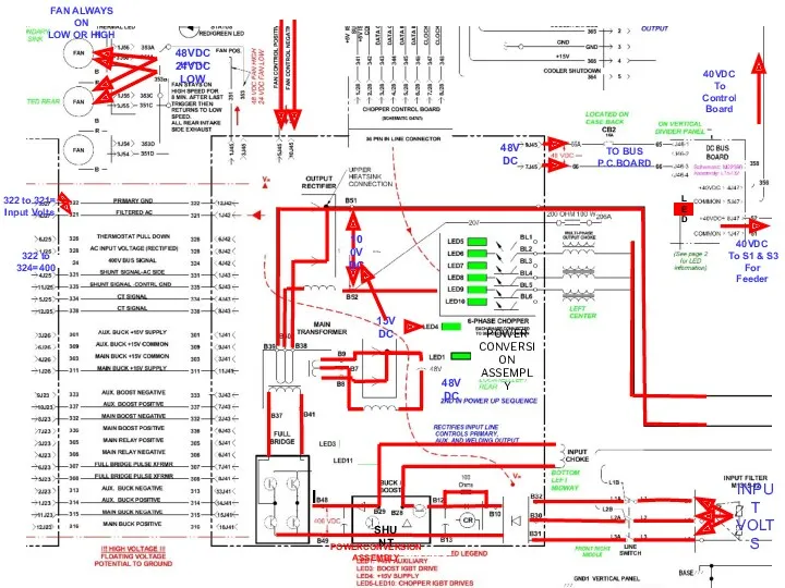
SHUNT
48VDC
48VDC HIGH
24VDC LOW
100VDC
48VDC
FAN ALWAYS ON
LOW OR HIGH
322 to 324=400
TO BUS
P.C.BOARD
LED
40VDC
To S1
SHUNT
48VDC
48VDC HIGH
24VDC LOW
100VDC
48VDC
FAN ALWAYS ON
LOW OR HIGH
322 to 324=400
TO BUS
P.C.BOARD
LED
40VDC
To S1
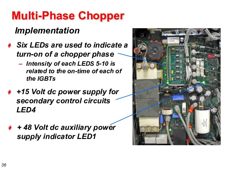
Implementation
Multi-Phase Chopper
+ 48 Volt dc auxiliary power supply indicator LED1
Six LEDs
Implementation
Multi-Phase Chopper
+ 48 Volt dc auxiliary power supply indicator LED1
Six LEDs
Functions
Control PC Board
Serves as the main communication interface
ArcLink master
Ethernet
Controls the Chopper
Functions
Control PC Board
Serves as the main communication interface
ArcLink master
Ethernet
Controls the Chopper
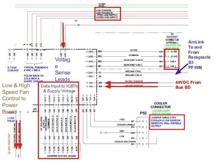
Data Input to IGBTs
& Supply Voltage
40VDC From
Bus BD
Low & High
Speed Fan
Control
Data Input to IGBTs
& Supply Voltage
40VDC From
Bus BD
Low & High
Speed Fan
Control
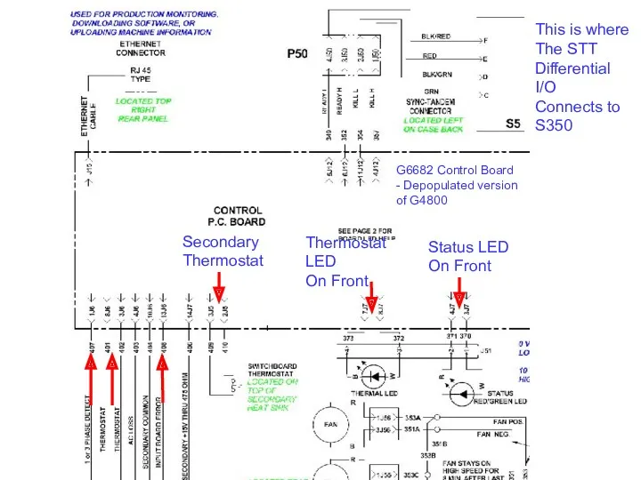
Secondary
Thermostat
Status LED
On Front
Thermostat LED
On Front
This is where
The STT
Differential I/O
Connects
Secondary
Thermostat
Status LED
On Front
Thermostat LED
On Front
This is where
The STT
Differential I/O
Connects
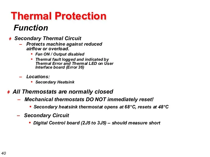
Thermal Protection
Function
Secondary Thermal Circuit
Protects machine against reduced airflow or overload.
Thermal Protection
Function
Secondary Thermal Circuit
Protects machine against reduced airflow or overload.
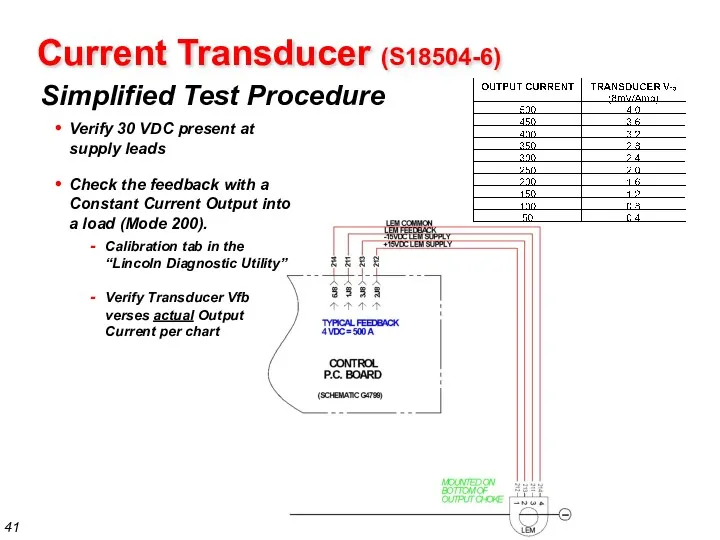
Simplified Test Procedure
Current Transducer (S18504-6)
Verify 30 VDC present at supply leads
Check
Simplified Test Procedure
Current Transducer (S18504-6)
Verify 30 VDC present at supply leads
Check
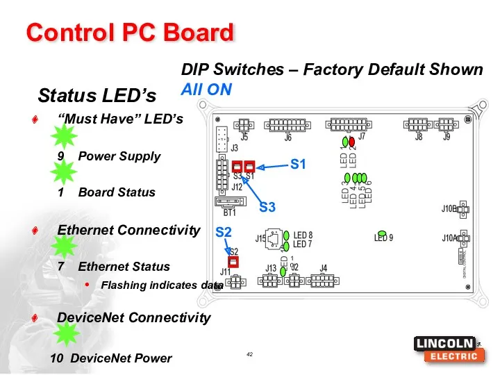
“Must Have” LED’s
10 DeviceNet Power
Status LED’s
Control PC Board
DIP Switches – Factory Default
“Must Have” LED’s
10 DeviceNet Power
Status LED’s
Control PC Board
DIP Switches – Factory Default
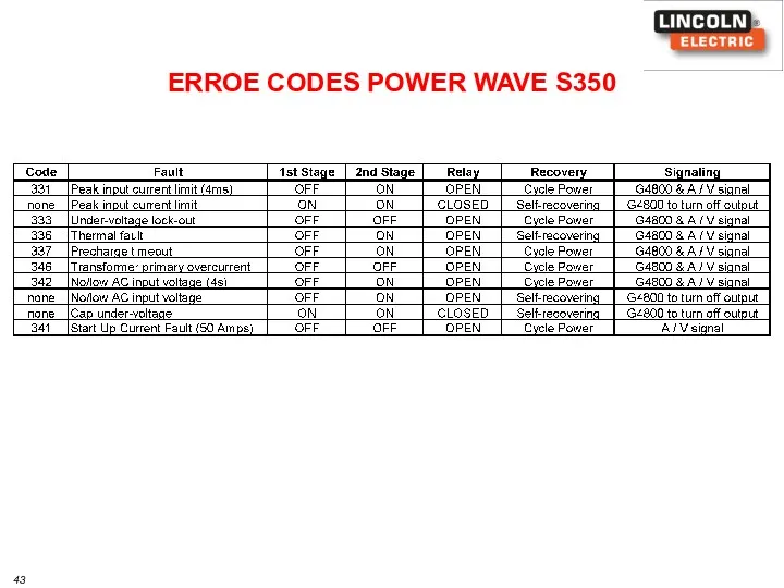
ERROE CODES POWER WAVE S350
ERROE CODES POWER WAVE S350
STT Module
Service Training
K2921-1
STT Module
Service Training
K2921-1

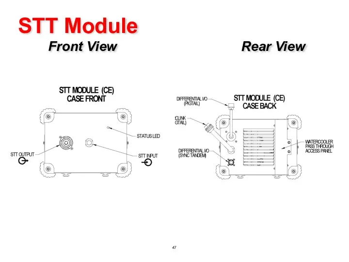
STT Module Front View Rear View
STT Module Front View Rear View
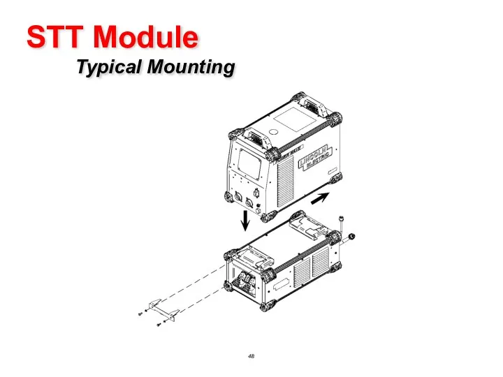
STT Module Typical Mounting
STT Module Typical Mounting
STT Module
Connection Diagram (CE) (Reference M22498)
STT Module
Connection Diagram (CE) (Reference M22498)
STT Module
STT Update Kit (CE) Included with K2921-1 for S350
STT Module
STT Update Kit (CE) Included with K2921-1 for S350
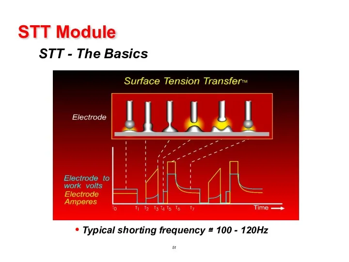
STT - The Basics
STT Module
Typical shorting frequency ≅ 100 - 120Hz
STT - The Basics
STT Module
Typical shorting frequency ≅ 100 - 120Hz
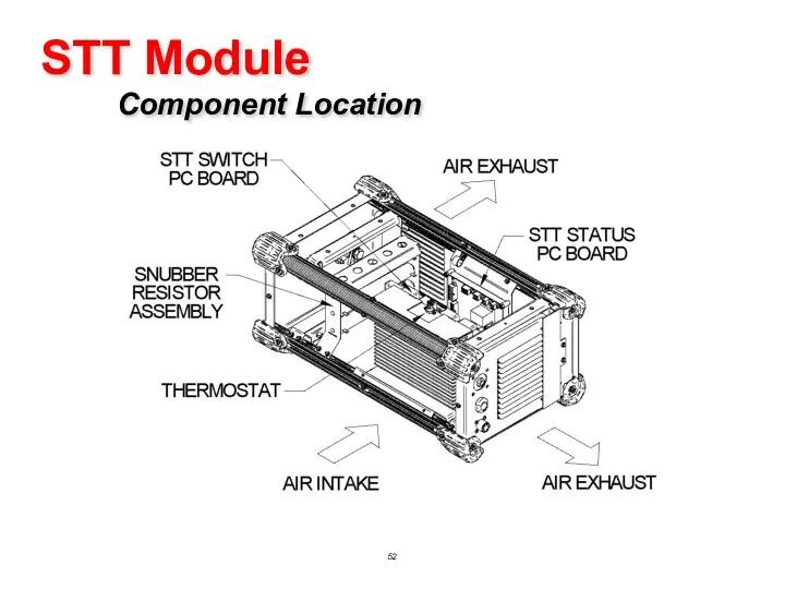
STT Module Component Location
STT Module Component Location
Functions
STT Status PC Board (S28250/G3884 series)
Identifies STT Module to ArcLink Network
Receives
Functions
STT Status PC Board (S28250/G3884 series)
Identifies STT Module to ArcLink Network
Receives
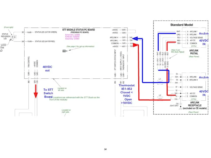
40VDC IN
40VDC out
To STT
Switch Board
Arclink
Thermostat
851-852
Closed < 1VDC
Open >10VDC
Arclink
40VDC IN
40VDC IN
40VDC out
To STT
Switch Board
Arclink
Thermostat
851-852
Closed < 1VDC
Open >10VDC
Arclink
40VDC IN
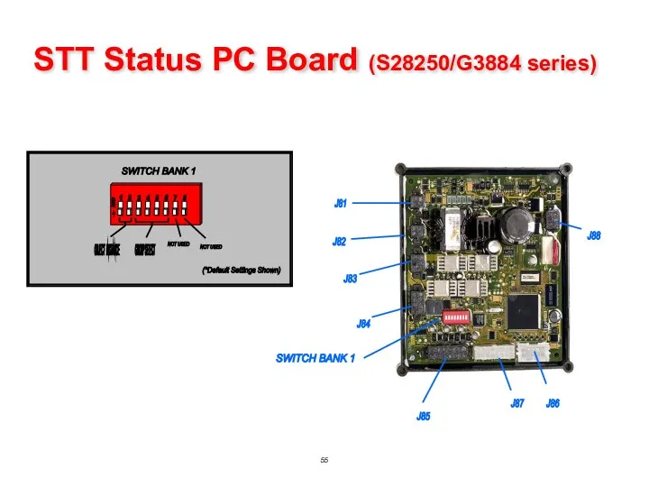
STT Status PC Board (S28250/G3884 series)
STT Status PC Board (S28250/G3884 series)
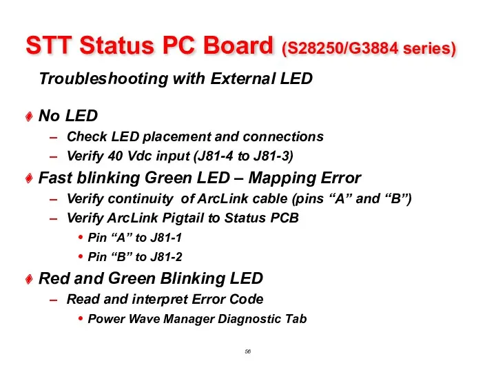
Troubleshooting with External LED
STT Status PC Board (S28250/G3884 series)
No LED
Troubleshooting with External LED
STT Status PC Board (S28250/G3884 series)
No LED
STT Status PC Board (S28250/G3884 series)
Troubleshooting with External LED
Error codes for
STT Status PC Board (S28250/G3884 series)
Troubleshooting with External LED
Error codes for
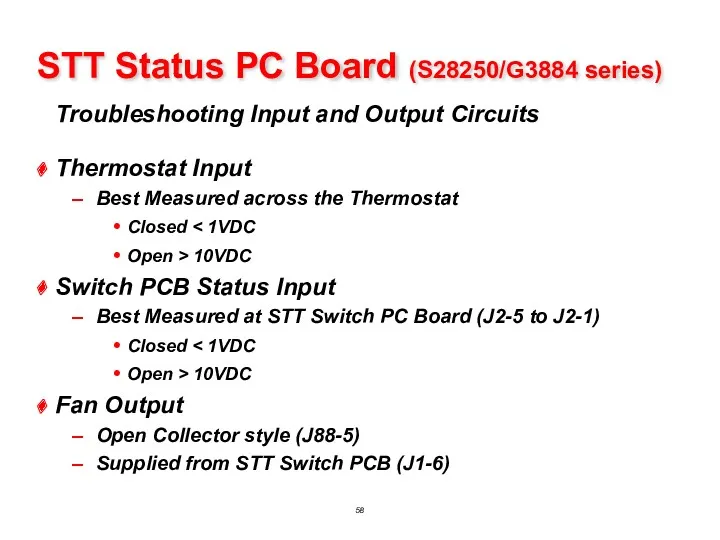
Troubleshooting Input and Output Circuits
STT Status PC Board (S28250/G3884 series)
Thermostat
Troubleshooting Input and Output Circuits
STT Status PC Board (S28250/G3884 series)
Thermostat
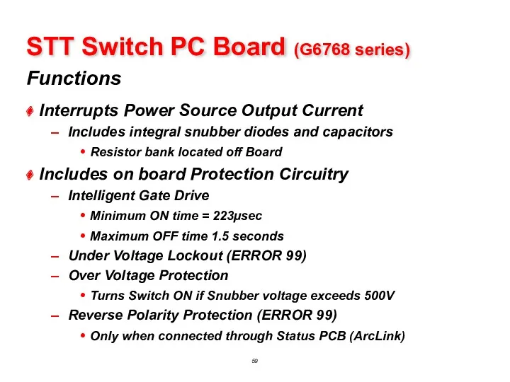
Functions
STT Switch PC Board (G6768 series)
Interrupts Power Source Output Current
Includes integral
Functions
STT Switch PC Board (G6768 series)
Interrupts Power Source Output Current
Includes integral
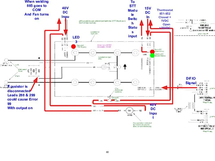
40VDC
Input
LED 3
15VDC
In
To STT
Module
Switch
Status
input
Thermostat
851-852
Closed < 1VDC
Open >10VDC
Dif IO
40VDC
Input
LED 3
15VDC
In
To STT
Module
Switch
Status
input
Thermostat
851-852
Closed < 1VDC
Open >10VDC
Dif IO
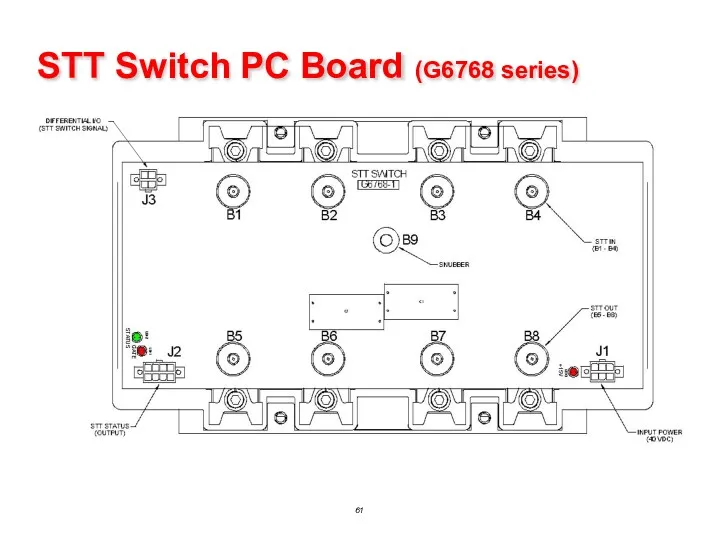
STT Switch PC Board (G6768 series)
STT Switch PC Board (G6768 series)
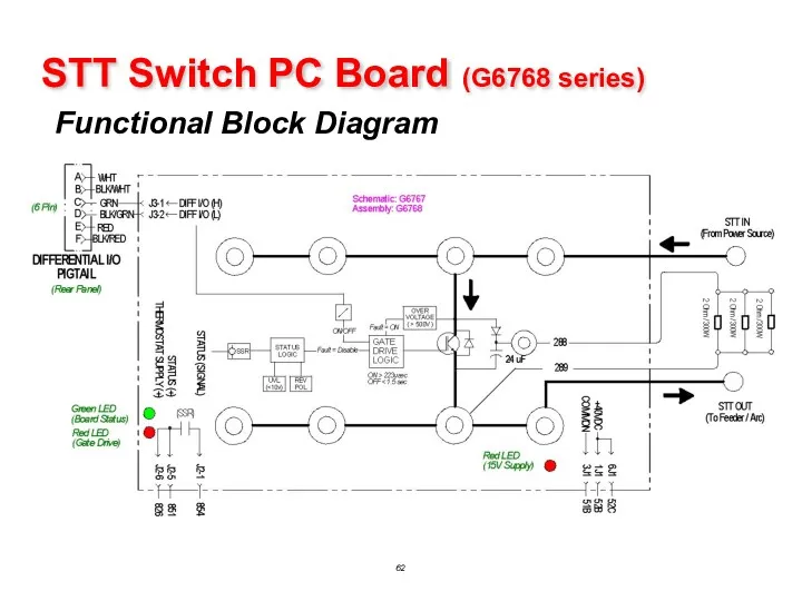
STT Switch PC Board (G6768 series)
Functional Block Diagram
STT Switch PC Board (G6768 series)
Functional Block Diagram
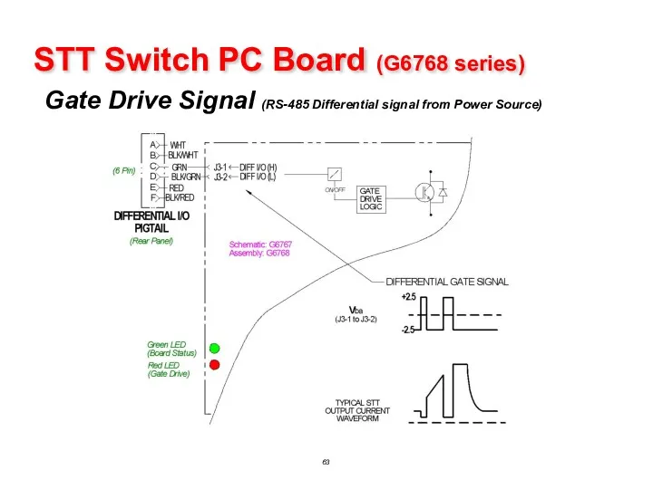
STT Switch PC Board (G6768 series)
Gate Drive Signal (RS-485 Differential signal
STT Switch PC Board (G6768 series)
Gate Drive Signal (RS-485 Differential signal
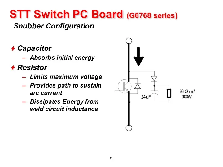
STT Switch PC Board (G6768 series)
Snubber Configuration
Capacitor
Absorbs initial energy
Resistor
Limits maximum
STT Switch PC Board (G6768 series)
Snubber Configuration
Capacitor
Absorbs initial energy
Resistor
Limits maximum
 Социальное партнерство школы с различными структурами
 Классный час Я выбираю добро Сценарий с презентацией.
 Февральская буржуазно-демократическая революция 1917 г
 Философия России. (Тема 6)
 Презентация Сюжетно-ролевая игра в развитии старших дошкольников
 Animals. Брейн-ринг
 Архитектурные конструкции общественных зданий (часть 1 - общая типология)
 Деление с остатком. Закрепление
 ОРКСЭ для родителей
 Методические указания к выполнению выпускной квалификационной работы для студентов. Профиль Бурение нефтяных и газовых скважин
 Законы Кеплера
 Роль грибов в природе и жизни человека
 Interior 5
 презентация -викторина по русским народным сказкам
 Экология. Экологические факторы
 Классификация экстремистских организации в России
 Век девятнадцатый, железный, воистину жестокий век! Общая характеристика русской литературы первой половины XIX века
 Визуально-оптические методы неразрушающего контроля проточной части авиационных двигателей, применяемых в условиях эксплуатации
 GTI Youngster
 Кто такие динозавры?
 Психофизическое развитие подростков (трудный возраст)
 Проект урока химии в 10 классе Физические и химические свойства алканов
 Красота в архитектуре
 Оформление научных и других студенческих работ
 Хроническая венозная недостаточность и женщины
 Урок 10 класс по теме Аминокислоты
 Электронные генераторы
 Презентация Тряпичная кукла Диск