- Section 5 Rotordynamics

Содержание
- 2. Table of Content Overview Rotordynamic Input--Versions 2004 & 2005 Whirl Modes Critical Speed Frequency Response Analysis
- 3. Table of Content (cont.) Campbell Diagram Rotor Centerline Grids Interior to a SE Modified Equations of
- 4. Overview
- 5. Introduction Main Focus: Jet Engines Three phase implementation
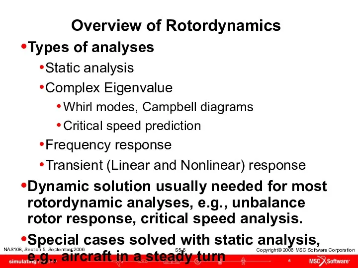
- 6. Overview of Rotordynamics Types of analyses Static analysis Complex Eigenvalue Whirl modes, Campbell diagrams Critical speed
- 7. Overview (cont.) Assumptions and Limitations Analysis performed in a stationary (inertial) coordinate system, i.e., non-rotating Models
- 8. Overview (cont.) Assumptions and Limitations Rotor axis is flexible, disks are rigid Critical speeds and modes
- 9. Theory: Basic Equations – Time Domain With Damping and Circulation Where = Total Mass Matrix =
- 10. Theory: Basic Equations (cont.) = support viscous damping equivalent to structural damping, (PARAM,G) = support viscous
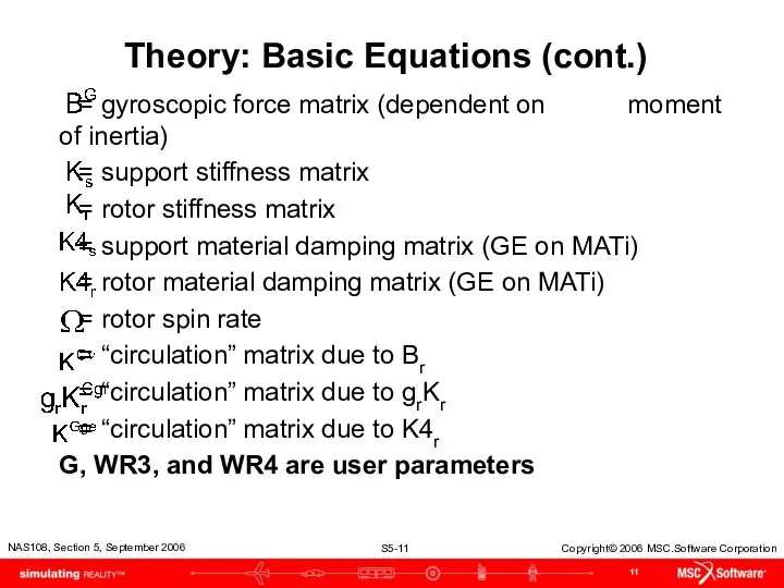
- 11. Theory: Basic Equations (cont.) = gyroscopic force matrix (dependent on moment of inertia) = support stiffness
- 12. Theory: Basic Equations – Frequency Domain Asynchronous Condition - With Damping and Circulation
- 13. Theory: Basic Equations – Frequency Domain Synchronous Condition – ω = Ω
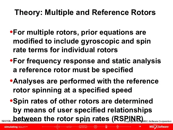
- 14. Theory: Multiple and Reference Rotors For multiple rotors, prior equations are modified to include gyroscopic and
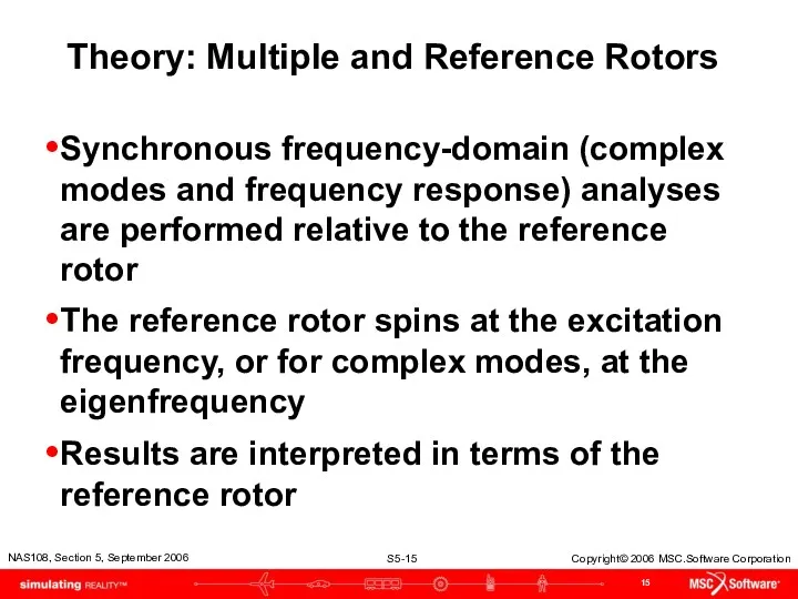
- 15. Theory: Multiple and Reference Rotors Synchronous frequency-domain (complex modes and frequency response) analyses are performed relative
- 16. Rotordynamic Input Versions 2004 & 2005
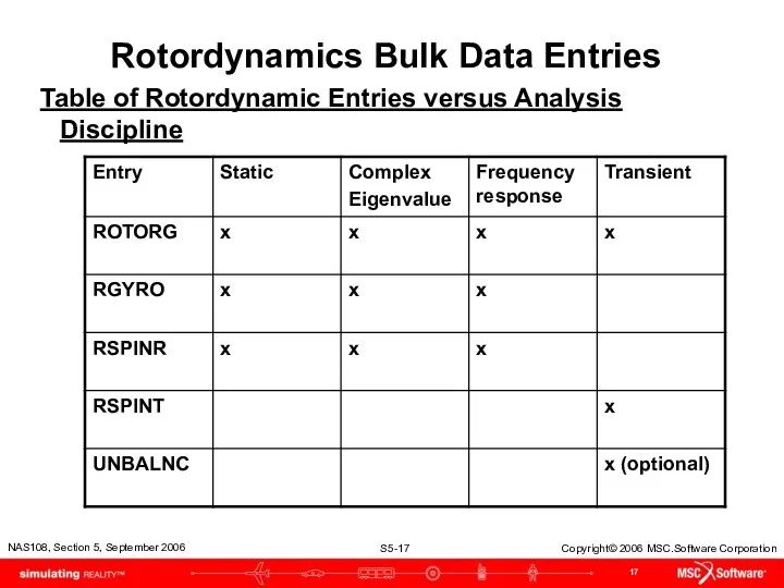
- 17. Rotordynamics Bulk Data Entries Table of Rotordynamic Entries versus Analysis Discipline
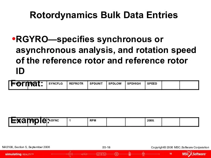
- 18. Rotordynamics Bulk Data Entries RGYRO—specifies synchronous or asynchronous analysis, and rotation speed of the reference rotor
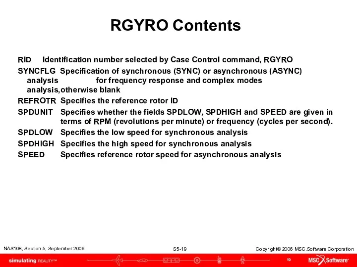
- 19. RGYRO Contents RID Identification number selected by Case Control command, RGYRO SYNCFLG Specification of synchronous (SYNC)
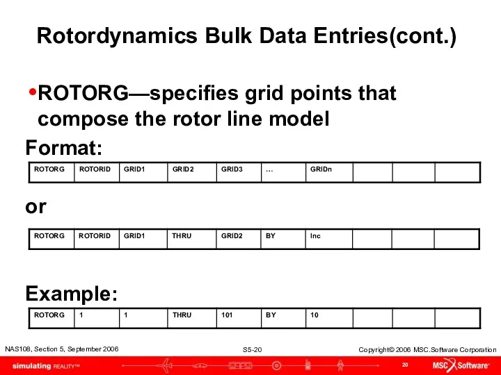
- 20. Rotordynamics Bulk Data Entries(cont.) ROTORG—specifies grid points that compose the rotor line model Format: or Example:
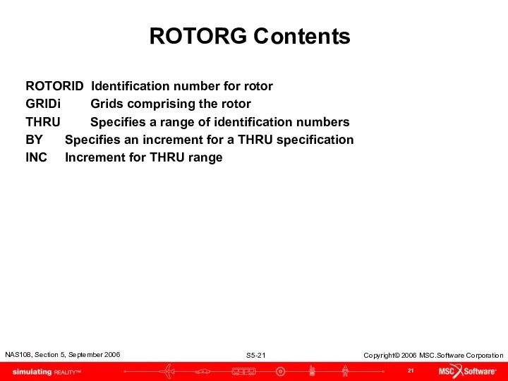
- 21. ROTORG Contents ROTORID Identification number for rotor GRIDi Grids comprising the rotor THRU Specifies a range
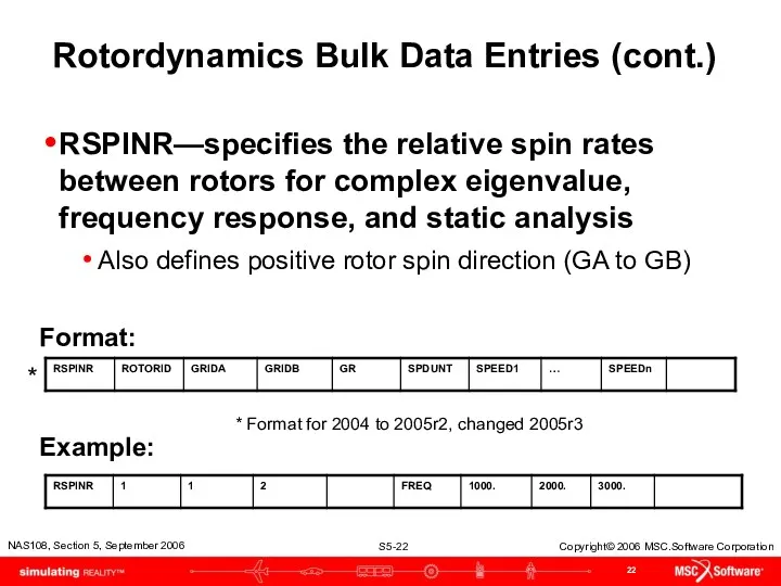
- 22. Rotordynamics Bulk Data Entries (cont.) RSPINR—specifies the relative spin rates between rotors for complex eigenvalue, frequency
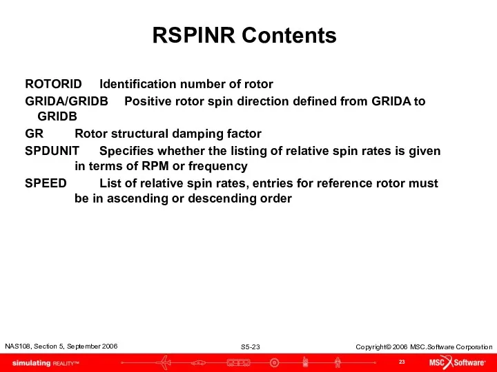
- 23. RSPINR Contents ROTORID Identification number of rotor GRIDA/GRIDB Positive rotor spin direction defined from GRIDA to
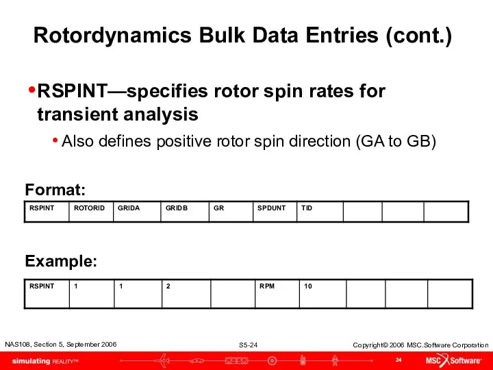
- 24. Rotordynamics Bulk Data Entries (cont.) RSPINT—specifies rotor spin rates for transient analysis Also defines positive rotor
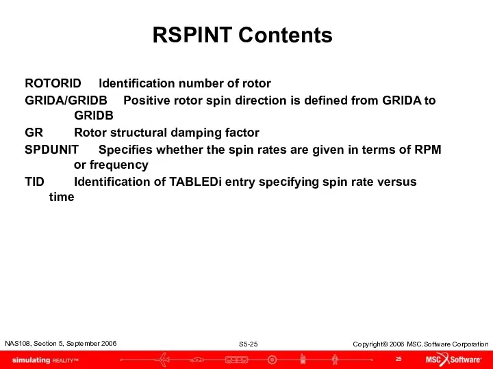
- 25. RSPINT Contents ROTORID Identification number of rotor GRIDA/GRIDB Positive rotor spin direction is defined from GRIDA
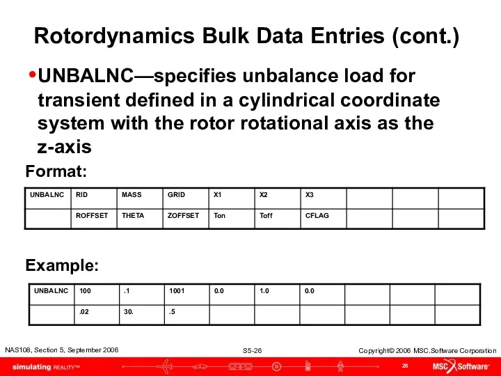
- 26. Rotordynamics Bulk Data Entries (cont.) UNBALNC—specifies unbalance load for transient defined in a cylindrical coordinate system
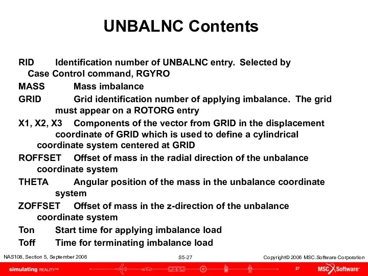
- 27. UNBALNC Contents RID Identification number of UNBALNC entry. Selected by Case Control command, RGYRO MASS Mass
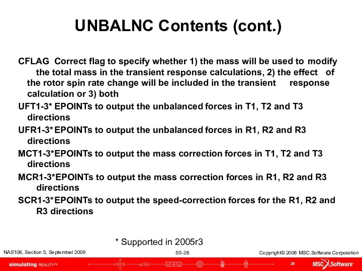
- 28. UNBALNC Contents (cont.) CFLAG Correct flag to specify whether 1) the mass will be used to
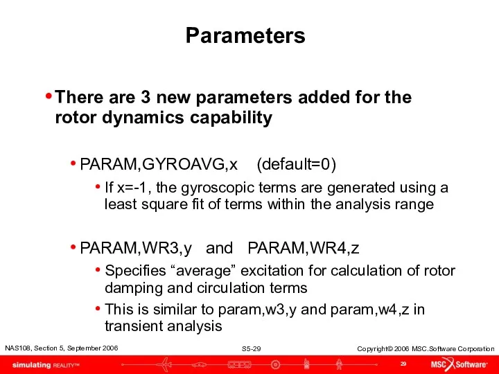
- 29. Parameters There are 3 new parameters added for the rotor dynamics capability PARAM,GYROAVG,x (default=0) If x=-1,
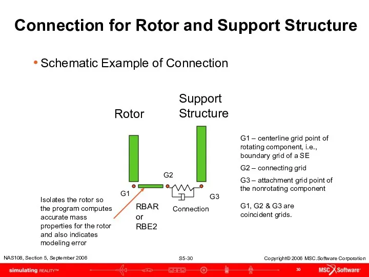
- 30. Connection for Rotor and Support Structure Rotor Support Structure RBAR or RBE2 Schematic Example of Connection
- 31. Comments Proper Rotor/Structure Connection avoids adding miscellaneous mass to the rotor and circulation damping terms caused
- 32. Dimentberg Example Shaft and Rigid Disk* Md = 0.0157 kg sec2/cm Id = 2.45 kg/sec2 cm
- 33. Rotordynamic Matrix Terms at One Point Matrix Terms for at One Point with Constant Spin Speed,
- 34. Rotordynamic Matrix Terms at One Point Matrix Terms for at One Point with Rotor Spin Speed,
- 35. Complex Eigenvalue Analysis Whirl Frequencies Beam model setup with DMIG gyroscopic coupling Beam model RGYRO setup
- 36. Line Model w/o Superelements CBAR Elements with CONM2 100 at Node 10 Node 10 Rotor support
- 37. Line Model (cont.) Is it possible to include rotordynamics effects without the using RGYRO capability or
- 38. Example Shaft and Disk, DMIG Setup ID ROTATING DISK SOL 107 CEND TITLE = GYROSCOPIC INFLUENCE
- 39. Whirl Modes
- 40. Example Shaft and Disk, RGYRO Setup ID ROTATING DISK SOL 107 CEND TITLE = GYROSCOPIC INFLUENCE
- 41. Results of Example Shaft and Disk, RGYRO or DMIG Yield Same Eigenvalues C O M P
- 42. Campbell Diagram – Non-SE Model Spin speed that matches the natural frequency, i.e., resonance
- 43. Critical Speed
- 44. Example Critical Speed Setup ID ROTATING DISK SOL 107 CEND TITLE = GYROSCOPIC INFLUENCE OF A
- 45. Results of Critical Speed Analysis C O M P L E X E I G E
- 46. Campbell Diagram – Non-SE Model 7.44 Hz 11.2 Hz 33.2 Hz
- 47. Frequency Response Analysis
- 48. Example Shaft and Disk, RGYRO Setup ID ROTATING DISK SOL 108 CEND TITLE = GYROSCOPIC INFLUENCE
- 49. Example Shaft and Disk, RGYRO Setup $ DISK MASS AND GYRO SPECIFICATIONS CONM2 100 10 157.0-4
- 50. Example Shaft & Disk Frequency Response – Forward Whirl The CBAR model with the forward whirl
- 51. Example 3-D Frequency Response – Forward Whirl The 3-D model with the forward whirl modes are
- 52. Nonlinear Transient Response Analysis
- 53. Transient Response Input Dimentberg rotor to illustrate UNBALNC input
- 54. Trans. Resp. Input File – 3D Rotor ID QUAD4 MODEL TIME 1000 DIAG 8 $,15,56 SOL
- 55. Trans. Resp. Input File – 3D Rotor (cont.) BEGIN BULK PARAM LGDISP 1 PARAM POST 0
- 56. Rotor Nonlinear Transient Response
- 57. MD Nastran 2006R1
- 58. Rotordynamics Bulk Data Entries Table of Rotordynamic Entries versus Analysis Discipline
- 59. High Lights Event | Date | Location (Optional Event Header) or MSC.Software Confidential (Optional Confidential Header)
- 60. Damping
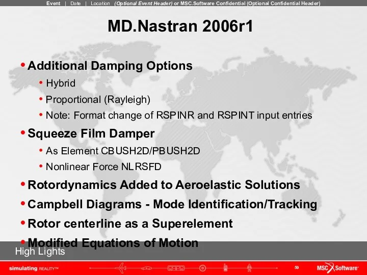
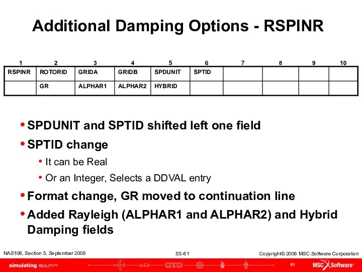
- 61. Additional Damping Options - RSPINR SPDUNIT and SPTID shifted left one field SPTID change It can
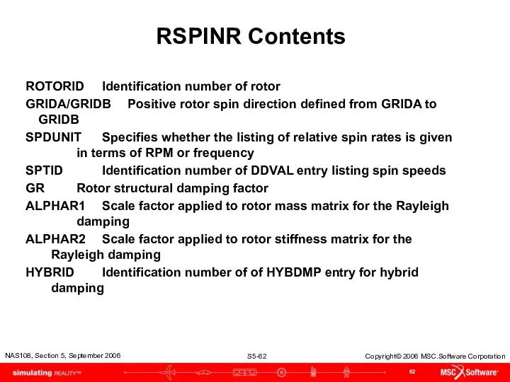
- 62. RSPINR Contents ROTORID Identification number of rotor GRIDA/GRIDB Positive rotor spin direction defined from GRIDA to
- 63. Additional Damping Options - RSPINT SPDUNIT,SPTID shifted left one field SPDOUT added to output spin speed
- 64. RSPINT Contents ROTORID Identification number of rotor GRIDA/GRIDB Positive rotor spin direction is defined from GRIDA
- 65. Additional Damping Options – HYBDAMP Hybrid modal damping for direct dynamic solutions Specifies the modes and
- 66. Squeeze Film Damper as Nonlinear Force The squeeze film damper (SFD) was implemented as a nonlinear
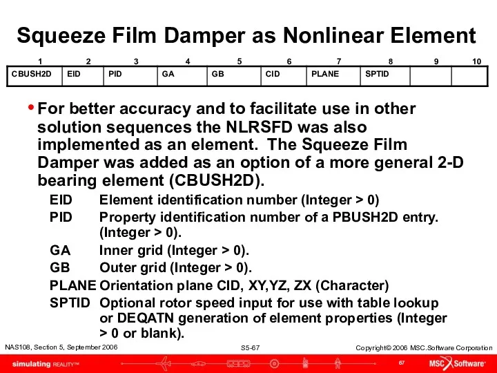
- 67. Squeeze Film Damper as Nonlinear Element For better accuracy and to facilitate use in other solution
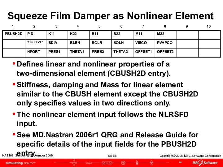
- 68. Squeeze Film Damper as Nonlinear Element Defines linear and nonlinear properties of a two-dimensional element (CBUSH2D
- 69. Rotors and Aeroelasticity
- 70. Gyroscopic Terms Added to Aeroelasticity SOL 145 and 146 have the same rotordynamic equations as complex
- 71. FSW Full Model Transient Response Plan View Side View
- 72. Canard Control Surface Input Deflection Time, sec. Canard Relative Rotation, rad.
- 73. Pitch, Roll and Yaw Response Grid 90 Rotation Displacement, rad. Time, sec.
- 74. Campbell Diagrams
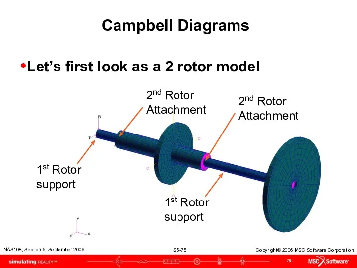
- 75. Campbell Diagrams Let’s first look as a 2 rotor model 1st Rotor support 1st Rotor support
- 76. Campbell Diagram for the 2 Rotor Model Run an asynchronous analysis with multiple subcases, import the
- 77. New Input to Generate Data for Campbell Diagrams Used in Complex Eigenvalue Analysis with SOL 107
- 78. CAMPBLL Bulk Data Parameters for Campbell diagram generation. CID Identification number of entry (Integer >0). VPARM
- 79. Campbell Diagram Data Generation Require Forward and Backward Rotor Mode Identification and Tracking Forward and backward
- 80. Rotor Centerline Grids Interior to a SE
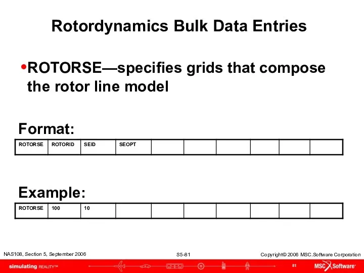
- 81. Rotordynamics Bulk Data Entries ROTORSE—specifies grids that compose the rotor line model Format: Example:
- 82. Modified Equations of Motion
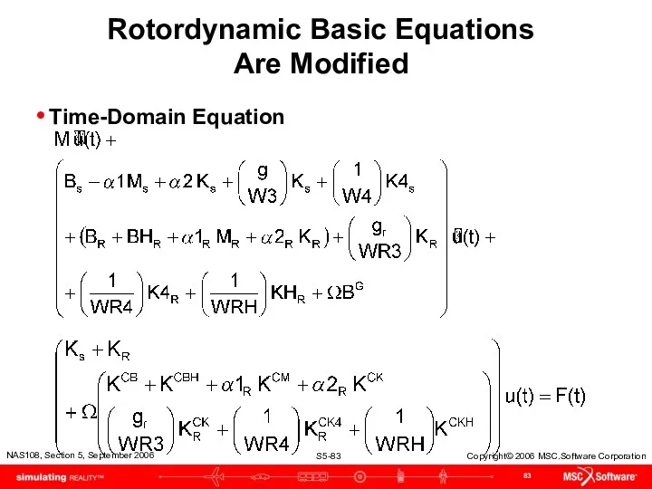
- 83. Rotordynamic Basic Equations Are Modified Time-Domain Equation
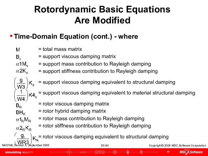
- 84. Rotordynamic Basic Equations Are Modified Time-Domain Equation (cont.) - where = total mass matrix = support
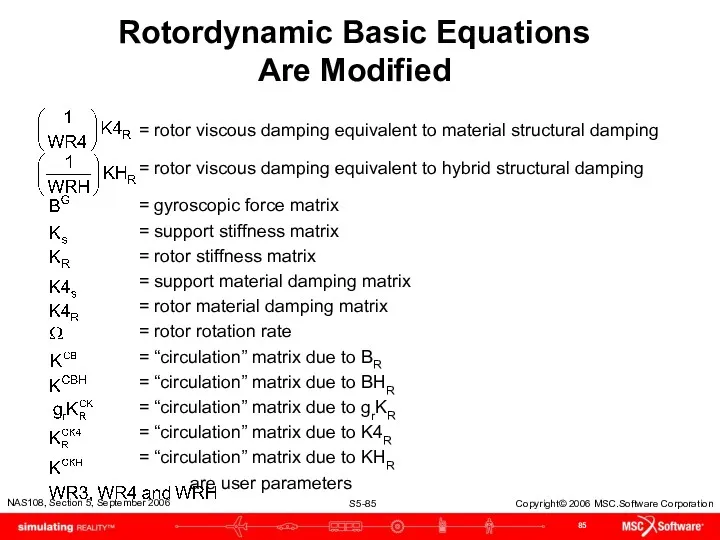
- 85. Rotordynamic Basic Equations Are Modified = rotor viscous damping equivalent to material structural damping = rotor
- 87. Скачать презентацию
Table of Content
Overview
Rotordynamic Input--Versions 2004 & 2005
Whirl Modes
Critical Speed
Frequency Response Analysis
Nonlinear
Table of Content
Overview
Rotordynamic Input--Versions 2004 & 2005
Whirl Modes
Critical Speed
Frequency Response Analysis
Nonlinear
Table of Content (cont.)
Campbell Diagram
Rotor Centerline Grids Interior to a SE
Modified
Table of Content (cont.)
Campbell Diagram
Rotor Centerline Grids Interior to a SE
Modified

Overview
Overview
Introduction
Main Focus: Jet Engines
Three phase implementation
Introduction
Main Focus: Jet Engines
Three phase implementation
Overview of Rotordynamics
Types of analyses
Static analysis
Complex Eigenvalue
Whirl modes, Campbell diagrams
Critical
Overview of Rotordynamics
Types of analyses
Static analysis
Complex Eigenvalue
Whirl modes, Campbell diagrams
Critical
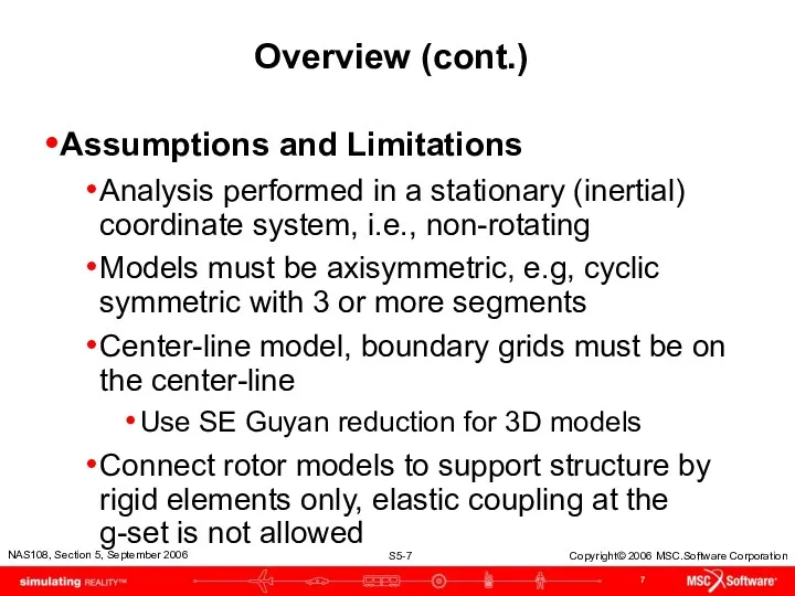
Overview (cont.)
Assumptions and Limitations
Analysis performed in a stationary (inertial) coordinate system,
Overview (cont.)
Assumptions and Limitations
Analysis performed in a stationary (inertial) coordinate system,
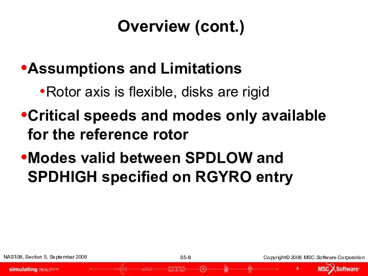
Overview (cont.)
Assumptions and Limitations
Rotor axis is flexible, disks are rigid
Critical speeds
Overview (cont.)
Assumptions and Limitations
Rotor axis is flexible, disks are rigid
Critical speeds
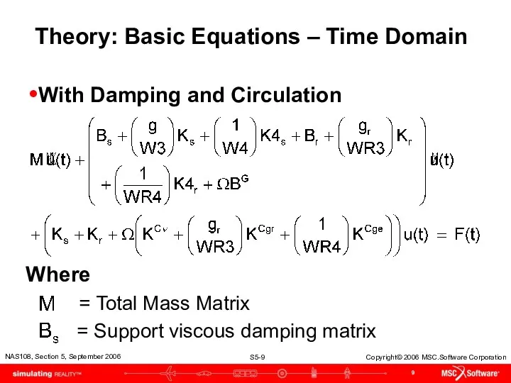
Theory: Basic Equations – Time Domain
With Damping and Circulation
Where
= Total
Theory: Basic Equations – Time Domain
With Damping and Circulation
Where
= Total
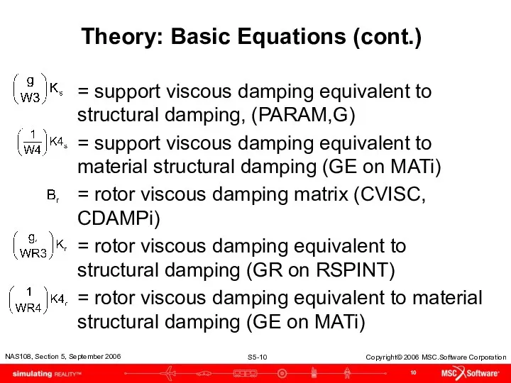
Theory: Basic Equations (cont.)
= support viscous damping equivalent to structural damping,
Theory: Basic Equations (cont.)
= support viscous damping equivalent to structural damping,
Theory: Basic Equations (cont.)
= gyroscopic force matrix (dependent on moment of
Theory: Basic Equations (cont.)
= gyroscopic force matrix (dependent on moment of
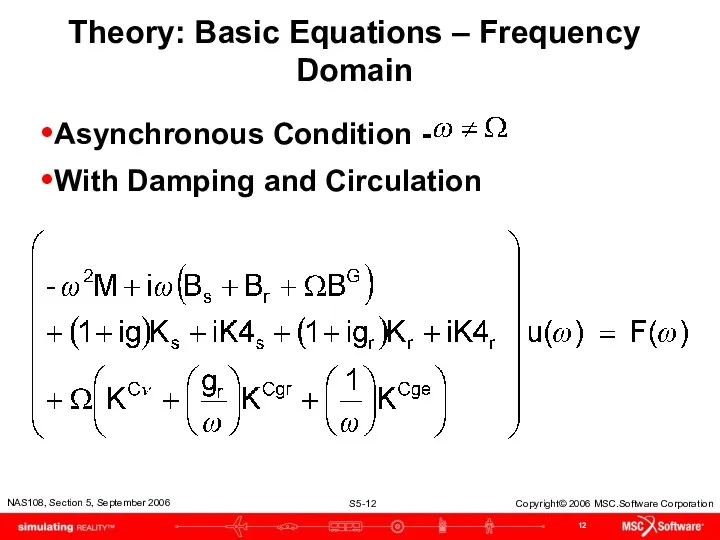
Theory: Basic Equations – Frequency Domain
Asynchronous Condition -
With Damping and
Theory: Basic Equations – Frequency Domain
Asynchronous Condition -
With Damping and
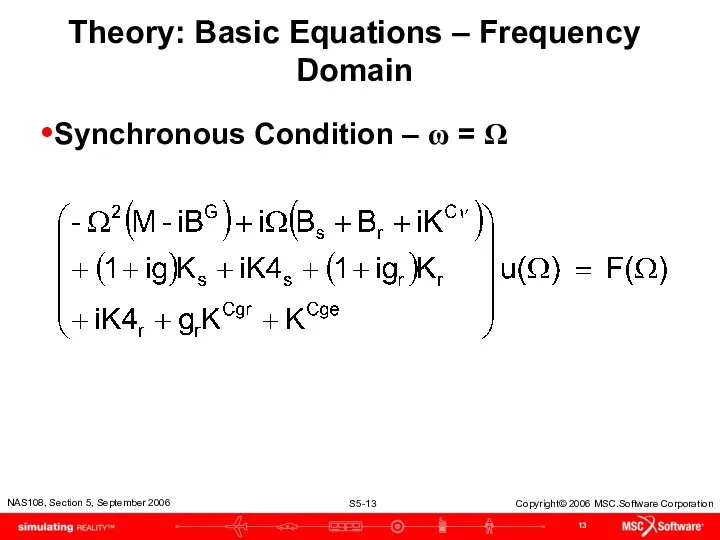
Theory: Basic Equations – Frequency Domain
Synchronous Condition – ω = Ω
Theory: Basic Equations – Frequency Domain
Synchronous Condition – ω = Ω
Theory: Multiple and Reference Rotors
For multiple rotors, prior equations are modified
Theory: Multiple and Reference Rotors
For multiple rotors, prior equations are modified
Theory: Multiple and Reference Rotors
Synchronous frequency-domain (complex modes and frequency response)
Theory: Multiple and Reference Rotors
Synchronous frequency-domain (complex modes and frequency response)
Rotordynamic Input
Versions 2004 & 2005
Rotordynamic Input
Versions 2004 & 2005
Rotordynamics Bulk Data Entries
Table of Rotordynamic Entries versus Analysis Discipline
Rotordynamics Bulk Data Entries
Table of Rotordynamic Entries versus Analysis Discipline
Rotordynamics Bulk Data Entries
RGYRO—specifies synchronous or asynchronous analysis, and rotation speed
Rotordynamics Bulk Data Entries
RGYRO—specifies synchronous or asynchronous analysis, and rotation speed
RGYRO Contents
RID Identification number selected by Case Control command, RGYRO
SYNCFLG Specification
RGYRO Contents
RID Identification number selected by Case Control command, RGYRO
SYNCFLG Specification
Rotordynamics Bulk Data Entries(cont.)
ROTORG—specifies grid points that compose the rotor line
Rotordynamics Bulk Data Entries(cont.)
ROTORG—specifies grid points that compose the rotor line
ROTORG Contents
ROTORID Identification number for rotor
GRIDi Grids comprising the rotor
THRU Specifies
ROTORG Contents
ROTORID Identification number for rotor
GRIDi Grids comprising the rotor
THRU Specifies
Rotordynamics Bulk Data Entries (cont.)
RSPINR—specifies the relative spin rates between rotors
Rotordynamics Bulk Data Entries (cont.)
RSPINR—specifies the relative spin rates between rotors
RSPINR Contents
ROTORID Identification number of rotor
GRIDA/GRIDB Positive rotor spin direction defined from GRIDA
RSPINR Contents
ROTORID Identification number of rotor
GRIDA/GRIDB Positive rotor spin direction defined from GRIDA
Rotordynamics Bulk Data Entries (cont.)
RSPINT—specifies rotor spin rates for transient analysis
Rotordynamics Bulk Data Entries (cont.)
RSPINT—specifies rotor spin rates for transient analysis
RSPINT Contents
ROTORID Identification number of rotor
GRIDA/GRIDB Positive rotor spin direction is defined from
RSPINT Contents
ROTORID Identification number of rotor
GRIDA/GRIDB Positive rotor spin direction is defined from
Rotordynamics Bulk Data Entries (cont.)
UNBALNC—specifies unbalance load for transient defined in
Rotordynamics Bulk Data Entries (cont.)
UNBALNC—specifies unbalance load for transient defined in
UNBALNC Contents
RID Identification number of UNBALNC entry. Selected by Case Control command,
UNBALNC Contents
RID Identification number of UNBALNC entry. Selected by Case Control command,
UNBALNC Contents (cont.)
CFLAG Correct flag to specify whether 1) the mass will
UNBALNC Contents (cont.)
CFLAG Correct flag to specify whether 1) the mass will
Parameters
There are 3 new parameters added for the rotor dynamics capability
PARAM,GYROAVG,x
Parameters
There are 3 new parameters added for the rotor dynamics capability
PARAM,GYROAVG,x
Connection for Rotor and Support Structure
Rotor
Support Structure
RBAR or RBE2
Schematic Example of
Connection for Rotor and Support Structure
Rotor
Support Structure
RBAR or RBE2
Schematic Example of
Comments
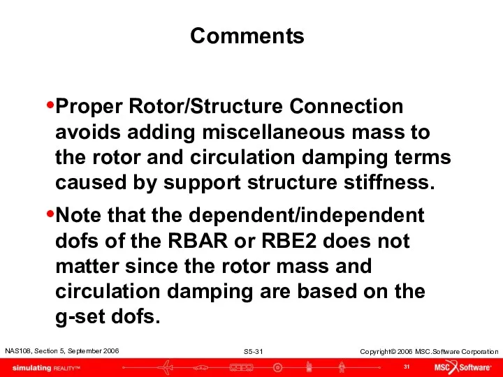
Proper Rotor/Structure Connection avoids adding miscellaneous mass to the rotor and
Comments
Proper Rotor/Structure Connection avoids adding miscellaneous mass to the rotor and
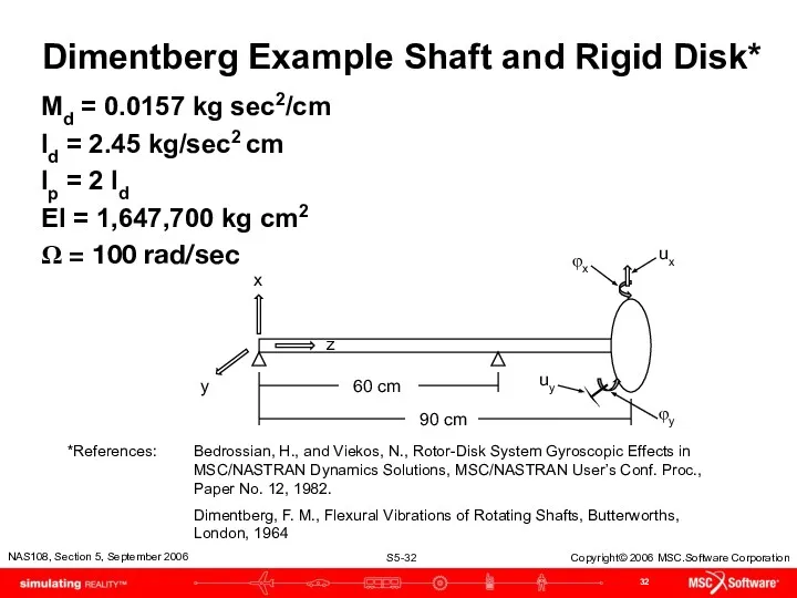
Dimentberg Example Shaft and Rigid Disk*
Md = 0.0157 kg sec2/cm
Id =
Dimentberg Example Shaft and Rigid Disk*
Md = 0.0157 kg sec2/cm
Id =
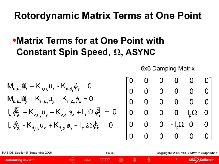
Rotordynamic Matrix Terms at One Point
Matrix Terms for at One Point
Rotordynamic Matrix Terms at One Point
Matrix Terms for at One Point
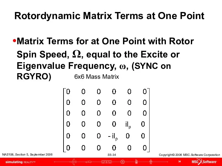
Rotordynamic Matrix Terms at One Point
Matrix Terms for at One Point
Rotordynamic Matrix Terms at One Point
Matrix Terms for at One Point
Complex Eigenvalue Analysis
Whirl Frequencies
Beam model setup with DMIG gyroscopic coupling
Beam model
Complex Eigenvalue Analysis
Whirl Frequencies
Beam model setup with DMIG gyroscopic coupling
Beam model
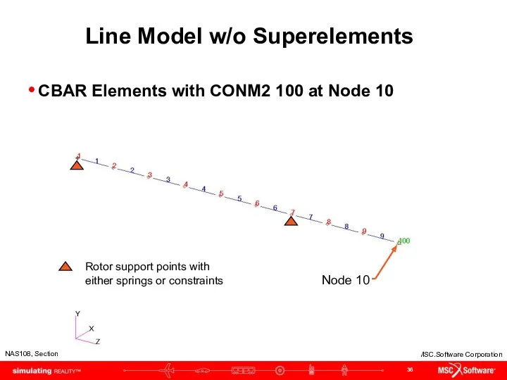
Line Model w/o Superelements
CBAR Elements with CONM2 100 at Node
Line Model w/o Superelements
CBAR Elements with CONM2 100 at Node
Line Model (cont.)
Is it possible to include rotordynamics effects without the
Line Model (cont.)
Is it possible to include rotordynamics effects without the
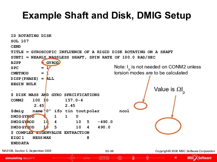
Example Shaft and Disk, DMIG Setup
ID ROTATING DISK
SOL 107
CEND
TITLE = GYROSCOPIC
Example Shaft and Disk, DMIG Setup
ID ROTATING DISK
SOL 107
CEND
TITLE = GYROSCOPIC
Whirl Modes
Whirl Modes
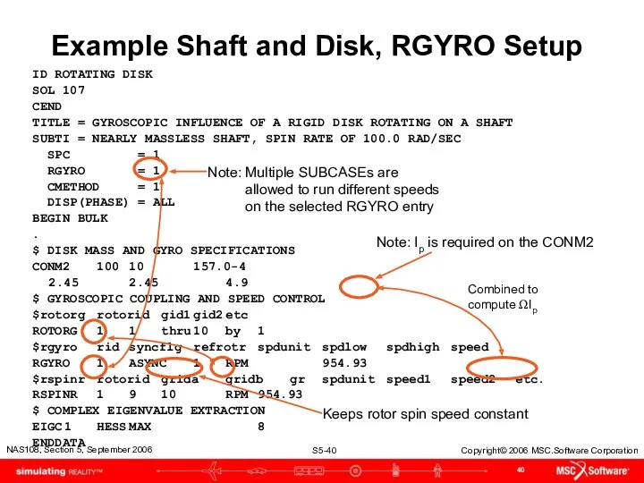
Example Shaft and Disk, RGYRO Setup
ID ROTATING DISK
SOL 107
CEND
TITLE = GYROSCOPIC
Example Shaft and Disk, RGYRO Setup
ID ROTATING DISK
SOL 107
CEND
TITLE = GYROSCOPIC
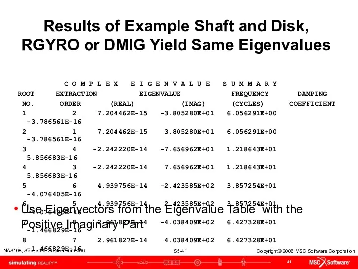
Results of Example Shaft and Disk, RGYRO or DMIG Yield Same
Results of Example Shaft and Disk, RGYRO or DMIG Yield Same
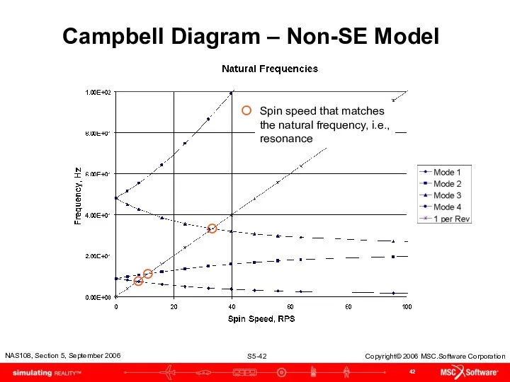
Campbell Diagram – Non-SE Model
Spin speed that matches the natural frequency,
Campbell Diagram – Non-SE Model
Spin speed that matches the natural frequency,
Critical Speed
Critical Speed
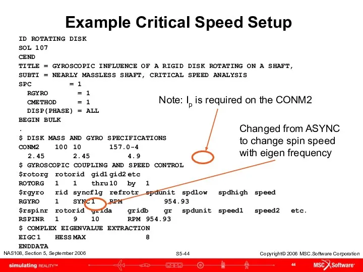
Example Critical Speed Setup
ID ROTATING DISK
SOL 107
CEND
TITLE = GYROSCOPIC INFLUENCE OF
Example Critical Speed Setup
ID ROTATING DISK
SOL 107
CEND
TITLE = GYROSCOPIC INFLUENCE OF
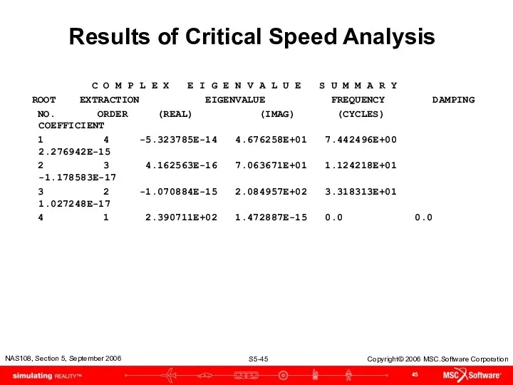
Results of Critical Speed Analysis
C O M P L E
Results of Critical Speed Analysis
C O M P L E
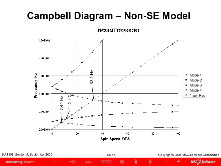
Campbell Diagram – Non-SE Model
7.44 Hz
11.2 Hz
33.2 Hz
Campbell Diagram – Non-SE Model
7.44 Hz
11.2 Hz
33.2 Hz
Frequency Response Analysis
Frequency Response Analysis
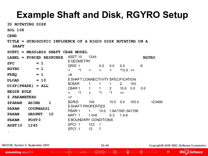
Example Shaft and Disk, RGYRO Setup
ID ROTATING DISK
SOL 108
CEND
TITLE = GYROSCOPIC
Example Shaft and Disk, RGYRO Setup
ID ROTATING DISK
SOL 108
CEND
TITLE = GYROSCOPIC
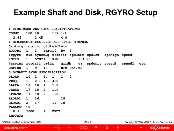
Example Shaft and Disk, RGYRO Setup
$ DISK MASS AND GYRO SPECIFICATIONS
CONM2 100 10 157.0-4
2.45 2.45 4.9
$
Example Shaft and Disk, RGYRO Setup
$ DISK MASS AND GYRO SPECIFICATIONS
CONM2 100 10 157.0-4
2.45 2.45 4.9
$
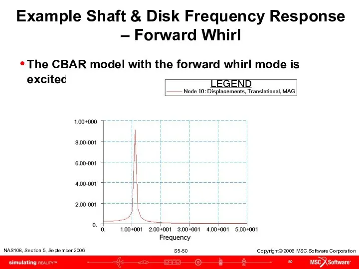
Example Shaft & Disk Frequency Response – Forward Whirl
The CBAR model
Example Shaft & Disk Frequency Response – Forward Whirl
The CBAR model
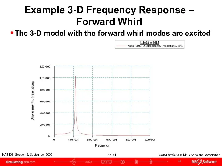
Example 3-D Frequency Response –
Forward Whirl
The 3-D model with the
Example 3-D Frequency Response –
Forward Whirl
The 3-D model with the
Nonlinear Transient Response Analysis
Nonlinear Transient Response Analysis
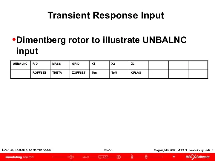
Transient Response Input
Dimentberg rotor to illustrate UNBALNC input
Transient Response Input
Dimentberg rotor to illustrate UNBALNC input
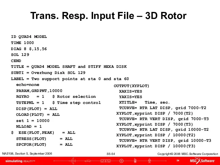
Trans. Resp. Input File – 3D Rotor
ID QUAD4 MODEL
TIME 1000
DIAG 8
Trans. Resp. Input File – 3D Rotor
ID QUAD4 MODEL
TIME 1000
DIAG 8
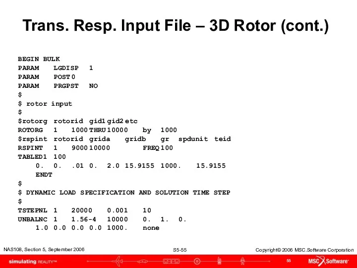
Trans. Resp. Input File – 3D Rotor (cont.)
BEGIN BULK
PARAM LGDISP 1
PARAM POST 0
PARAM PRGPST NO
$
$ rotor input
$
$rotorg rotorid gid1 gid2 etc
ROTORG 1 1000 THRU 10000 by 1000
$rspint rotorid grida gridb gr spdunit teid
RSPINT 1 9000 10000 FREQ 100
TABLED1 100
0. 0. .01 0. 2.0 15.9155 1000. 15.9155
ENDT
$
$
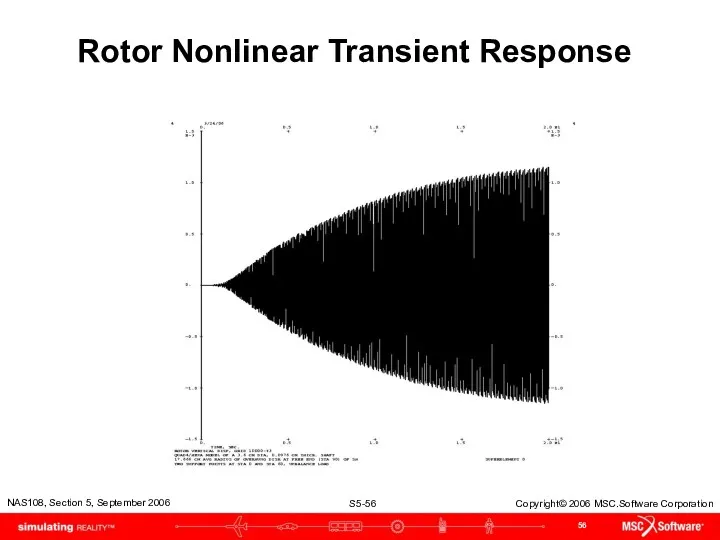
Rotor Nonlinear Transient Response
Rotor Nonlinear Transient Response
MD Nastran 2006R1
MD Nastran 2006R1
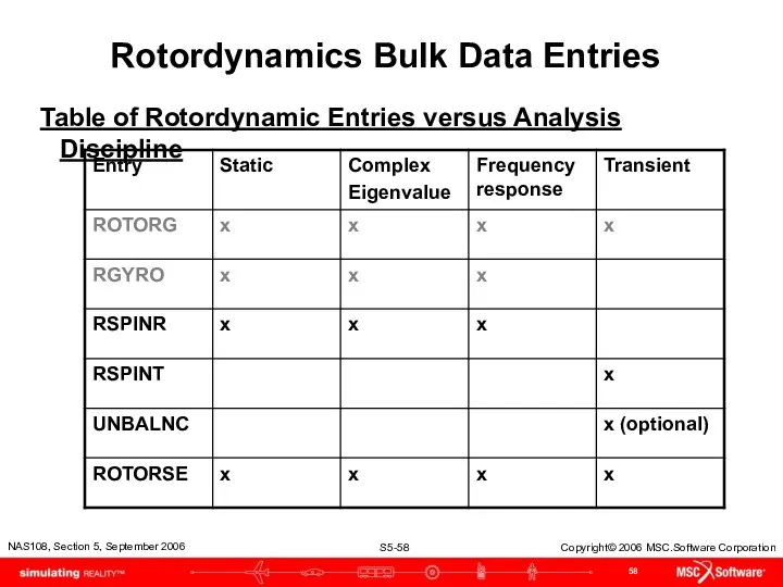
Rotordynamics Bulk Data Entries
Table of Rotordynamic Entries versus Analysis Discipline
Rotordynamics Bulk Data Entries
Table of Rotordynamic Entries versus Analysis Discipline
High Lights
Event | Date | Location (Optional Event Header) or MSC.Software
High Lights
Event | Date | Location (Optional Event Header) or MSC.Software
Damping
Damping
Additional Damping Options - RSPINR
SPDUNIT and SPTID shifted left one field
SPTID
Additional Damping Options - RSPINR
SPDUNIT and SPTID shifted left one field
SPTID
RSPINR Contents
ROTORID Identification number of rotor
GRIDA/GRIDB Positive rotor spin direction defined from GRIDA
RSPINR Contents
ROTORID Identification number of rotor
GRIDA/GRIDB Positive rotor spin direction defined from GRIDA
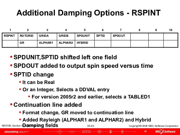
Additional Damping Options - RSPINT
SPDUNIT,SPTID shifted left one field
SPDOUT added to
Additional Damping Options - RSPINT
SPDUNIT,SPTID shifted left one field
SPDOUT added to
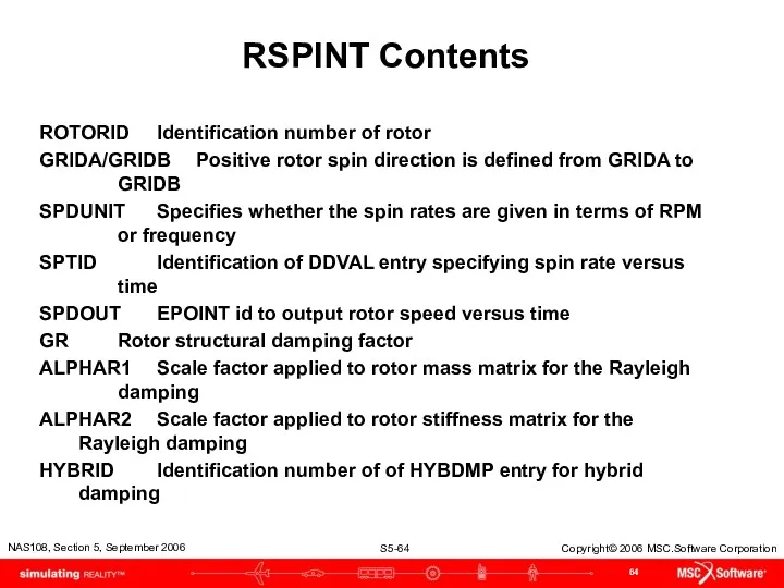
RSPINT Contents
ROTORID Identification number of rotor
GRIDA/GRIDB Positive rotor spin direction is defined from
RSPINT Contents
ROTORID Identification number of rotor
GRIDA/GRIDB Positive rotor spin direction is defined from
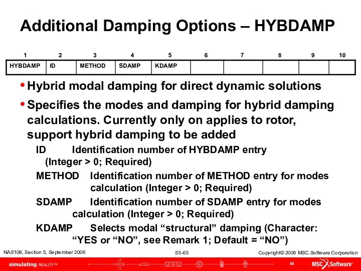
Additional Damping Options – HYBDAMP
Hybrid modal damping for direct dynamic solutions
Specifies
Additional Damping Options – HYBDAMP
Hybrid modal damping for direct dynamic solutions
Specifies
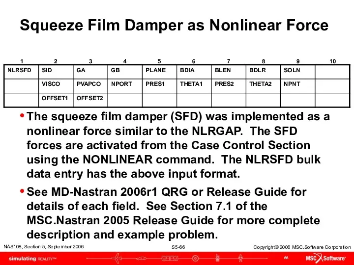
Squeeze Film Damper as Nonlinear Force
The squeeze film damper (SFD) was
Squeeze Film Damper as Nonlinear Force
The squeeze film damper (SFD) was
Squeeze Film Damper as Nonlinear Element
For better accuracy and to facilitate
Squeeze Film Damper as Nonlinear Element
For better accuracy and to facilitate
Squeeze Film Damper as Nonlinear Element
Defines linear and nonlinear properties of
Squeeze Film Damper as Nonlinear Element
Defines linear and nonlinear properties of
Rotors and Aeroelasticity
Rotors and Aeroelasticity
Gyroscopic Terms Added to Aeroelasticity
SOL 145 and 146 have the same
Gyroscopic Terms Added to Aeroelasticity
SOL 145 and 146 have the same
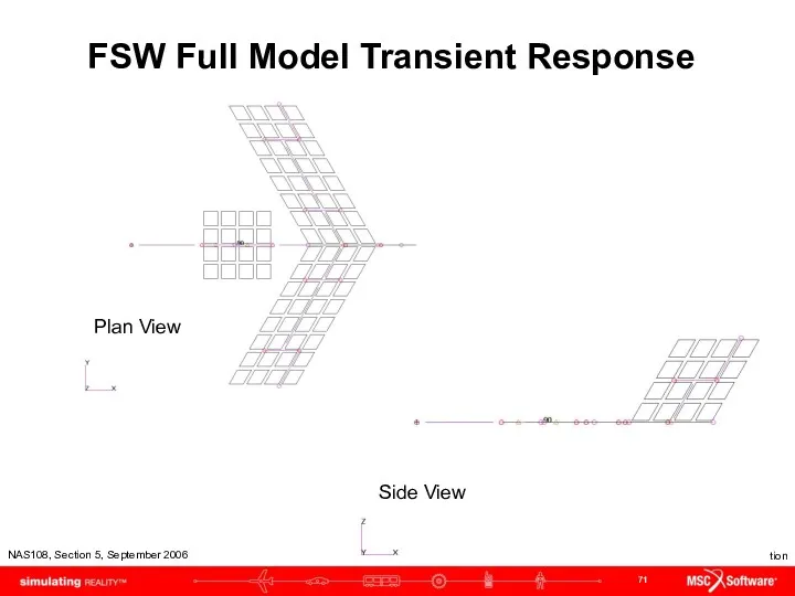
FSW Full Model Transient Response
Plan View
Side View
FSW Full Model Transient Response
Plan View
Side View
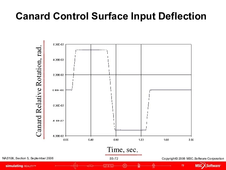
Canard Control Surface Input Deflection
Time, sec.
Canard Relative Rotation, rad.
Canard Control Surface Input Deflection
Time, sec.
Canard Relative Rotation, rad.
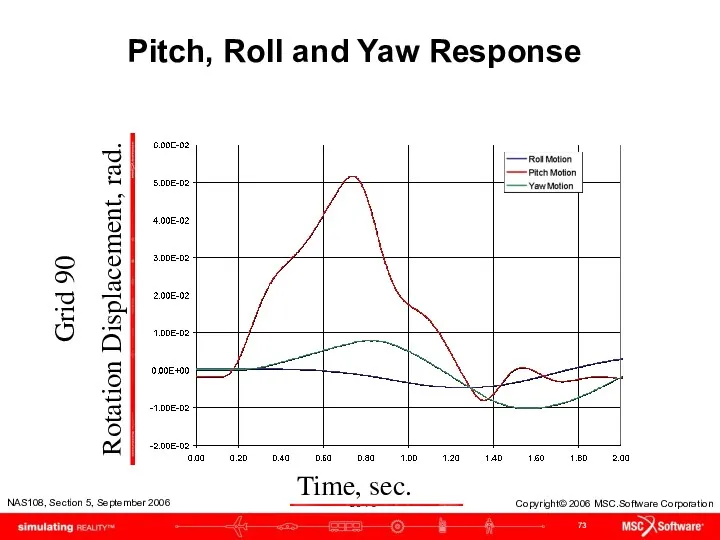
Pitch, Roll and Yaw Response
Grid 90
Rotation Displacement, rad.
Time, sec.
Pitch, Roll and Yaw Response
Grid 90
Rotation Displacement, rad.
Time, sec.
Campbell Diagrams
Campbell Diagrams
Campbell Diagrams
Let’s first look as a 2 rotor model
1st Rotor support
1st
Campbell Diagrams
Let’s first look as a 2 rotor model
1st Rotor support
1st
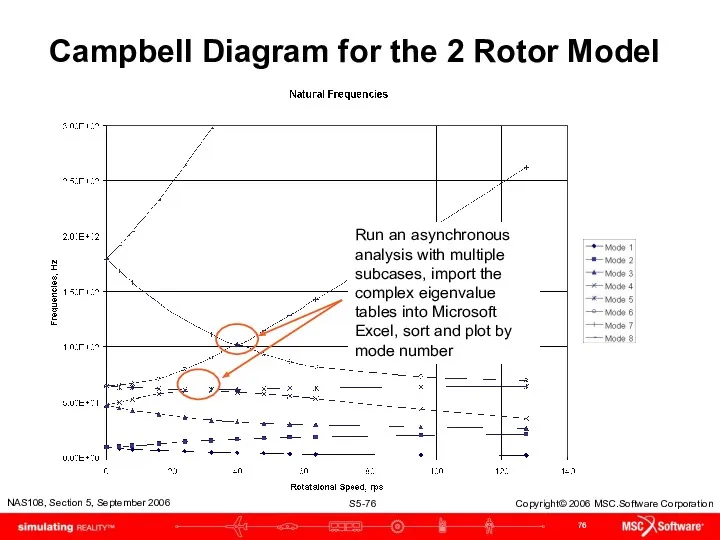
Campbell Diagram for the 2 Rotor Model
Run an asynchronous analysis with
Campbell Diagram for the 2 Rotor Model
Run an asynchronous analysis with
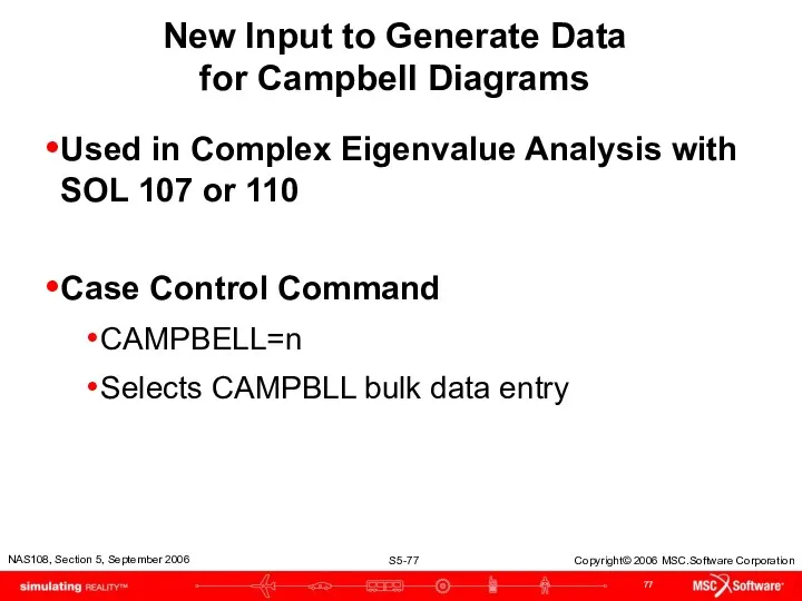
New Input to Generate Data
for Campbell Diagrams
Used in Complex Eigenvalue
New Input to Generate Data
for Campbell Diagrams
Used in Complex Eigenvalue
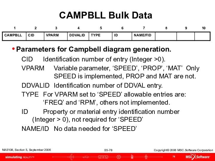
CAMPBLL Bulk Data
Parameters for Campbell diagram generation.
CID Identification number of entry (Integer
CAMPBLL Bulk Data
Parameters for Campbell diagram generation.
CID Identification number of entry (Integer
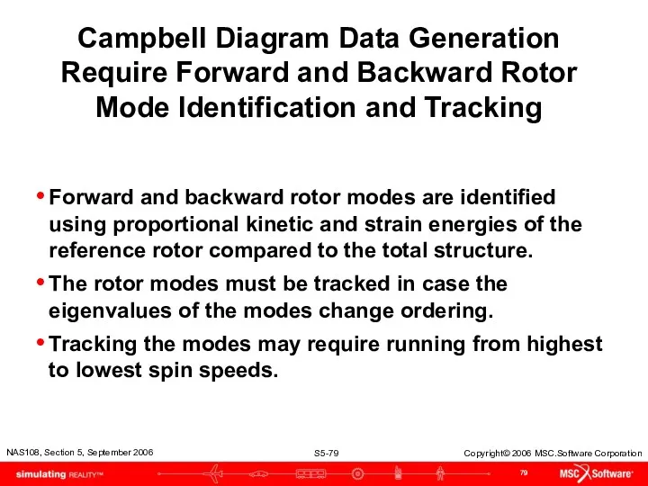
Campbell Diagram Data Generation Require Forward and Backward Rotor Mode Identification
Campbell Diagram Data Generation Require Forward and Backward Rotor Mode Identification
Rotor Centerline Grids Interior to a SE
Rotor Centerline Grids Interior to a SE
Rotordynamics Bulk Data Entries
ROTORSE—specifies grids that compose the rotor line model
Format:
Example:
Rotordynamics Bulk Data Entries
ROTORSE—specifies grids that compose the rotor line model
Format:
Example:
Modified Equations of Motion
Modified Equations of Motion
Rotordynamic Basic Equations
Are Modified
Time-Domain Equation
Rotordynamic Basic Equations
Are Modified
Time-Domain Equation
Rotordynamic Basic Equations
Are Modified
Time-Domain Equation (cont.) - where
= total mass
Rotordynamic Basic Equations
Are Modified
Time-Domain Equation (cont.) - where
= total mass
Rotordynamic Basic Equations
Are Modified
= rotor viscous damping equivalent to material
Rotordynamic Basic Equations
Are Modified
= rotor viscous damping equivalent to material
 Минеральная косметика TM ChocoLatte
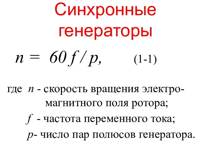 Синхронные генераторы
 Презентация химия 9 класс: Коррозия металлов
 Бессмертный Полк
 Сахара, соли, аминокислоты, минералы
 Пожаро-взрывоопасные объекты: классификации, причины пожаров и профилактика
 Кошки
Кошки Как создавать газету
 Распространение Церкви Христовой до пределов вселенной
 Специфика философского анализа общества
 Будова клітини рослин
 мастер класс Рождественский венок.
 Республика Аргентина
 Определение напряжений в предварительно напряженных конструкциях
 Визитка хореографического ансамбля Души исполненный полёт
 Презентация по правилам использования корпоративного шаблона в рамках СМК
 Производитель высококачественных полотенцесушителей с двадцатилетней историей
 Теракты в России и в мире
 Круговорот веществ. 11 класс
 Народная кукла, как средство приобщения детей дошкольного возраста к русской традиционной культуре
 Родительское благословение – духовно-нравственная ценность семьи в мировых религиях.
 Презентация Рождество Христово
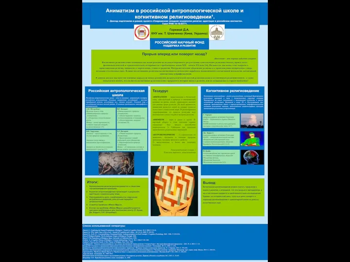 Аниматизм в российской антропологической школе и когнитивном религиоведении
 Русский футуризм. Поэзия
 Лепка – технология жгута. Художественные образы природной среды: В мире насекомых
 Семейное чтение, как источник формирования интереса к книге и духовного обогащения семьи.
 Презентация Викторина по сказкам Андерсена. Программа PowerPoit
 Социальное воспитание подростков с девиантным поведением