- Swisscross tutti. En assembly manual

Содержание
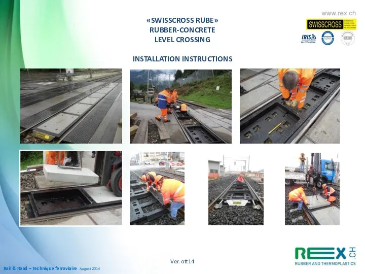
- 2. Rail & Road – Technique ferroviaire August 2014 Ver. ott14 «SWISSCROSS RUBE» RUBBER-CONCRETE LEVEL CROSSING INSTALLATION
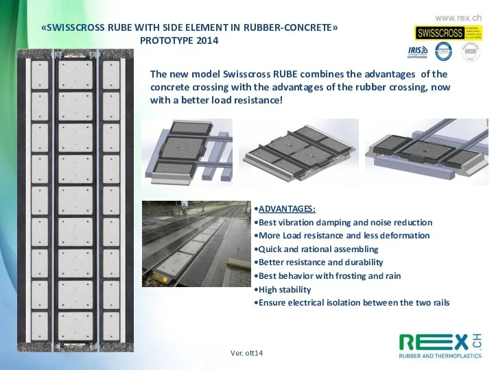
- 3. Advantages Best vibration damping and noise reduction More Load resistance and less deformation to the passage
- 4. Ver. ott14 Rubber-concrete level crossing «SWISSCROSS RUBE» gauge: 1000 – 1435 – 1524 – 1600 mm
- 5. INSTALLATION INSTRUCTION FOR SWISSCROSS PASSAGE AT RUBE 1. USE This statement relates to the execution of
- 6. RUBE 1000 with side elements in rubber RUBE 1435 with side elements in rubber RUBE 1000
- 7. 2. NECESSARY EQUIPMENTS AND TOOLS FOR INSTALLATION (see attached list) - Power driven lifting wagon to
- 8. In the area of the level passage you need to enclose the old filling outside the
- 9. 3.2 Mounting rubber elements First mark the center of the passage on the rails. The installation
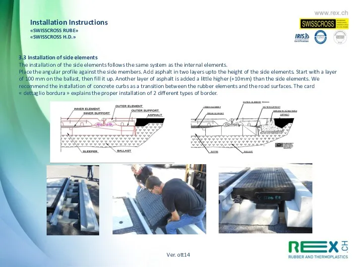
- 10. 3.3 Installation of concrete elements Grease the walls of the rubber element and the walls of
- 11. Ver. ott14 Installation Instructions «SWISSCROSS RUBE» «SWISSCROSS H.D.»
- 12. RUBE 1000 Assembly Details: 1 2 4 3 Cleaning of the track and laying of supports
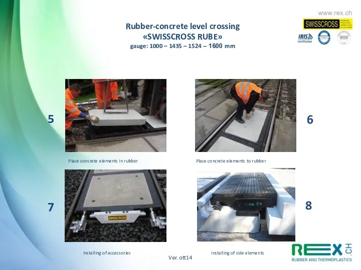
- 13. 5 6 7 Place concrete elements in rubber Place concrete elements to rubber Installing of accessories
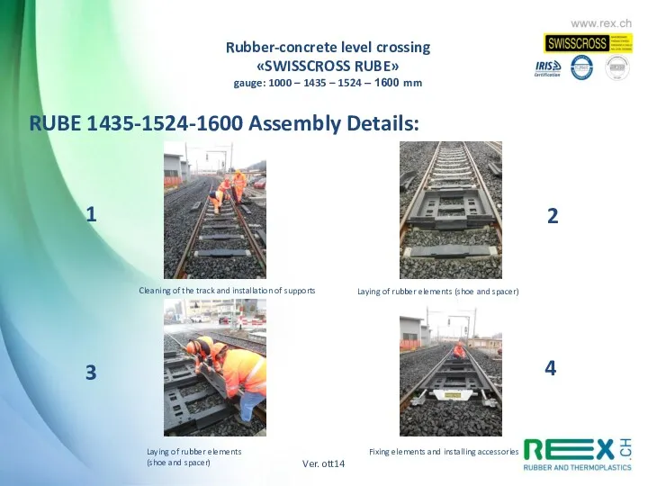
- 14. 1 2 3 4 RUBE 1435-1524-1600 Assembly Details: Cleaning of the track and installation of supports
- 15. 5 6 7 8 Placing concrete elements in rubber Placing concrete elements in rubber Tightening screws
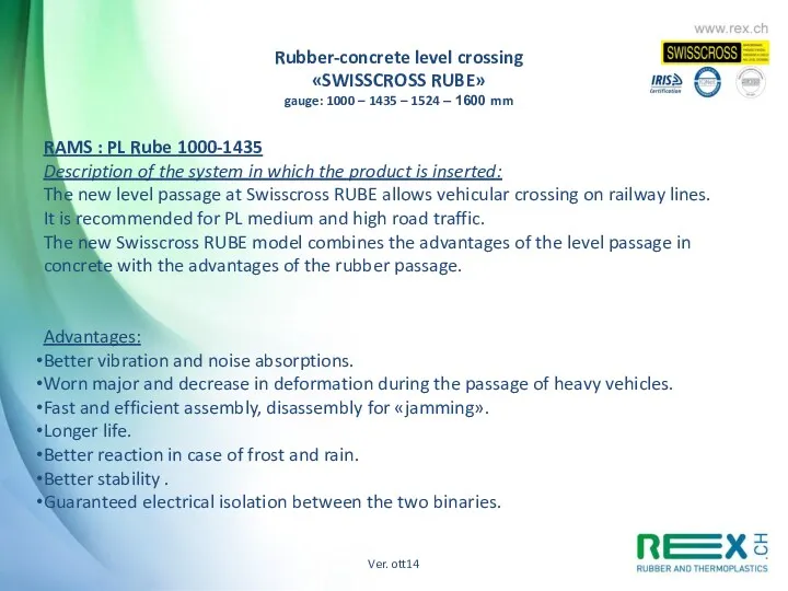
- 16. RAMS : PL Rube 1000-1435 Description of the system in which the product is inserted: The
- 17. RAMS : PL Rube 1000-1435 Description of the environnement in which the product has been introduced:
- 18. RAMS : PL Rube 1000-1435 Reliability : The Swisscross Rube level passage is guaranteed for 5
- 19. RAMS : PL Rube 1000-1435 Security For the installation of the Swisscross level passage enforce safety
- 20. RAMS : PL Rube 1000-1435 Availability Swisscross ensures the supply of wear parts in Europe within
- 21. RAMS : PL Rube 1000-1435 Handling, packaging , transport and storage Handling of rubber elements must
- 22. RAMS : PL Rube 1000-1435 Disposal of waste: The rubber elements must be disposed of as
- 23. «SWISSCROSS RUBE WITH SIDE ELEMENT IN RUBBER-CONCRETE» PROTOTYPE 2014 The new model Swisscross RUBE combines the
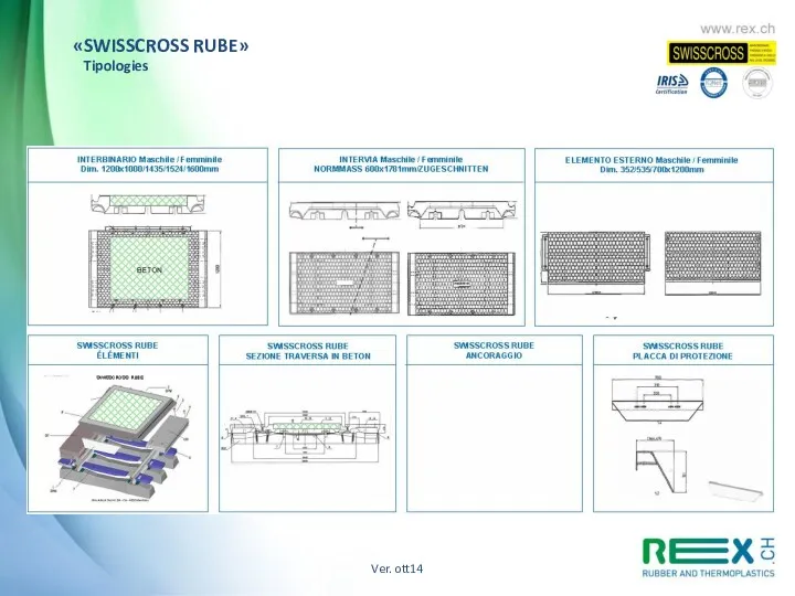
- 24. Ver. ott14 «SWISSCROSS RUBE» Tipologies
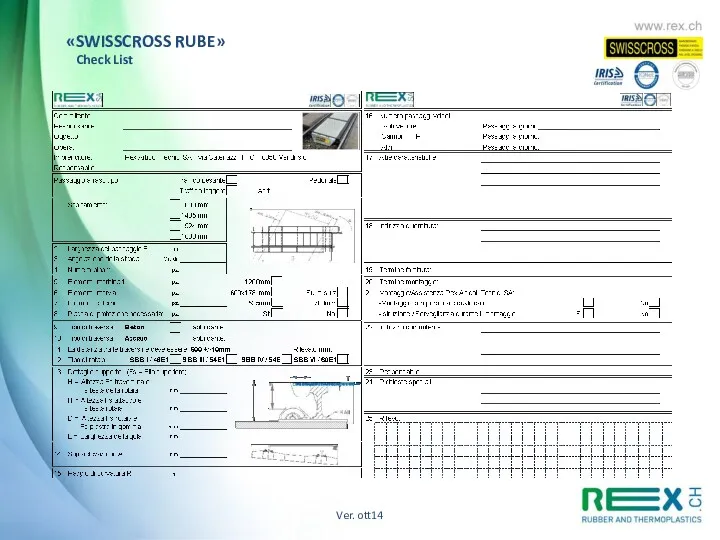
- 25. Ver. ott14 «SWISSCROSS RUBE» Check List
- 26. Rail & road – Bahntechnik «SWISSCROSS H.D.» Curve radius «SWISSCROSS H.D.» Service «SWISSCROSS H.D.» Heavy Duty
- 27. INSTALLATION INSTRUCTIONS APPLICATION 2. REQUIRED EQUIPMENT AND TOOLS 3. ASSEMBLY 3.1 Ground preparation 3.2 Assembly of
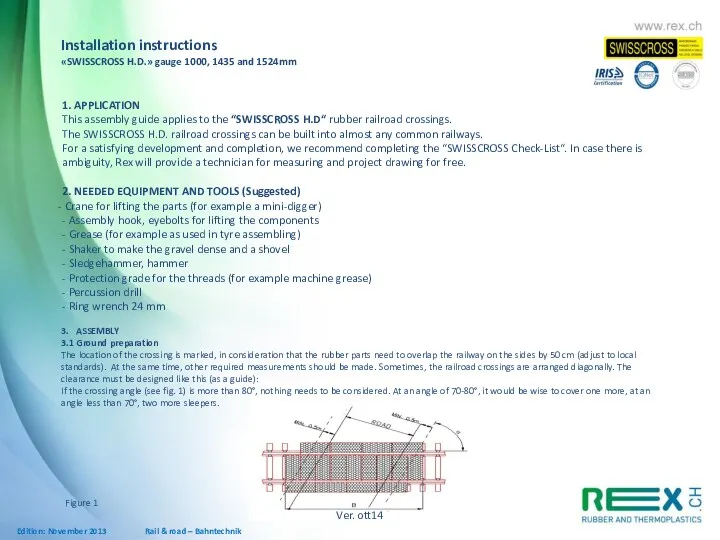
- 28. 1. APPLICATION This assembly guide applies to the “SWISSCROSS H.D“ rubber railroad crossings. The SWISSCROSS H.D.
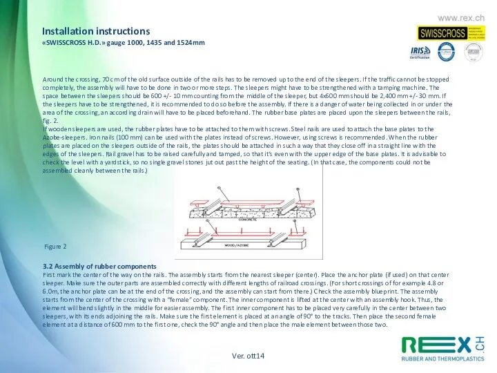
- 29. Around the crossing, 70 cm of the old surface outside of the rails has to be
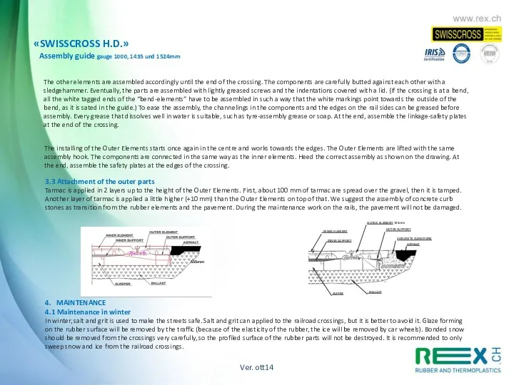
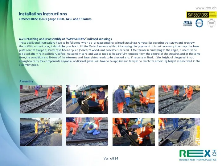
- 30. «SWISSCROSS H.D.» Assembly guide gauge 1000, 1435 und 1524mm The other elements are assembled accordingly until
- 31. 4.2 Detaching and reassembly of ”SWISSCROSS“ railroad crossings These additional instructions have to be followed when
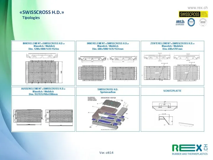
- 32. Ver. ott14 «SWISSCROSS H.D.» Tipologies
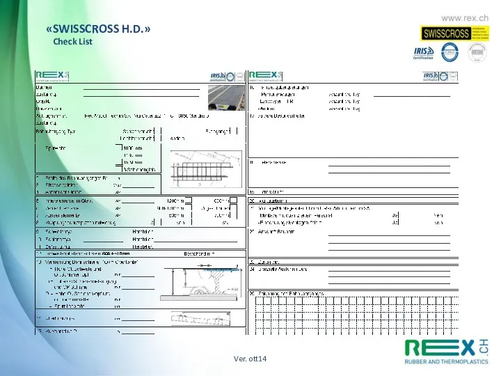
- 33. Ver. ott14 «SWISSCROSS H.D.» Check List
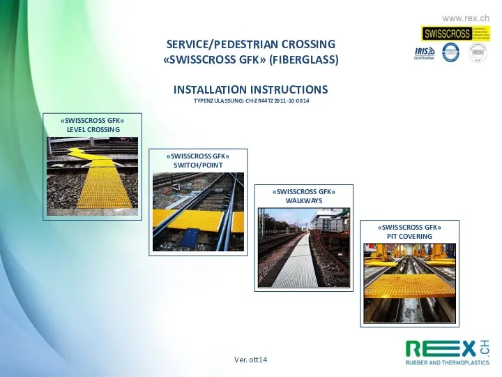
- 34. «SWISSCROSS GFK» LEVEL CROSSING «SWISSCROSS GFK» PIT COVERING «SWISSCROSS GFK» SWITCH/POINT «SWISSCROSS GFK» WALKWAYS Ver. ott14
- 35. Ver. ott14 Service/pedestrian crossing «SWISSCROSS GFK» INSTALLATION INSTRUCTIONS FIELD OF APPLICATION 2. TOOLS AND MATERIALS REQUIRED
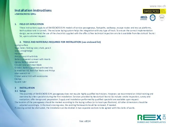
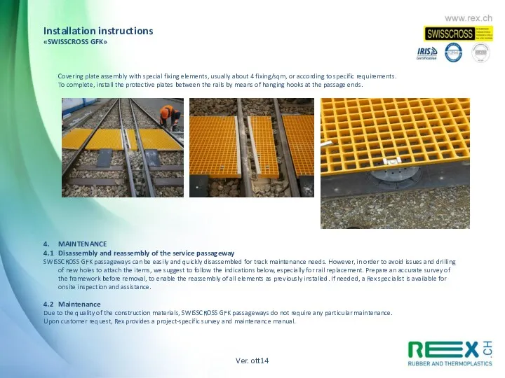
- 36. 1. FIELD OF APPLICATION These instructions apply to all SWISSCROSS GFK models of service passageways, footpaths,
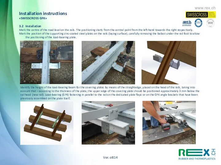
- 37. Identify the height of the load-bearing beam for the covering plates by means of the straightedge,
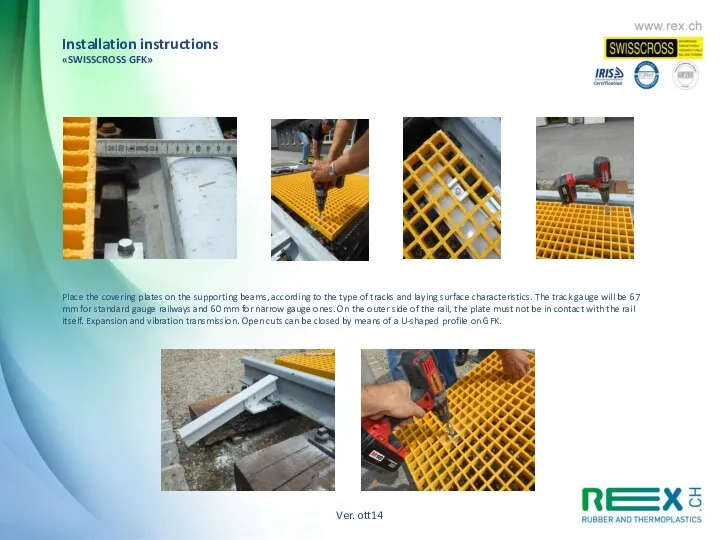
- 38. Place the covering plates on the supporting beams, according to the type of tracks and laying
- 39. Covering plate assembly with special fixing elements, usually about 4 fixing/sqm, or according to specific requirements.
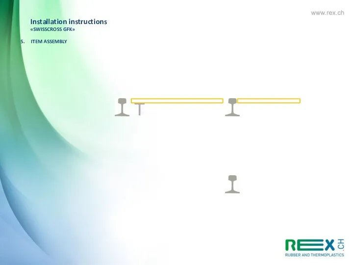
- 40. Installation instructions «SWISSCROSS GFK» 5. ITEM ASSEMBLY SECTION: Sleeper: Wood – Cement - Steel LEANING OUTER
- 41. Installation instructions «SWISSCROSS GFK» 5. ITEM ASSEMBLY Ver. ott14
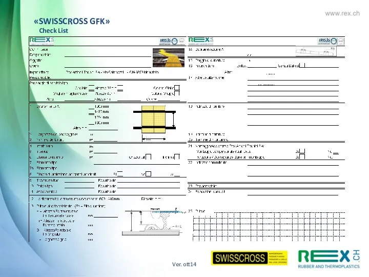
- 42. Ver. ott14 «SWISSCROSS GFK» Check List
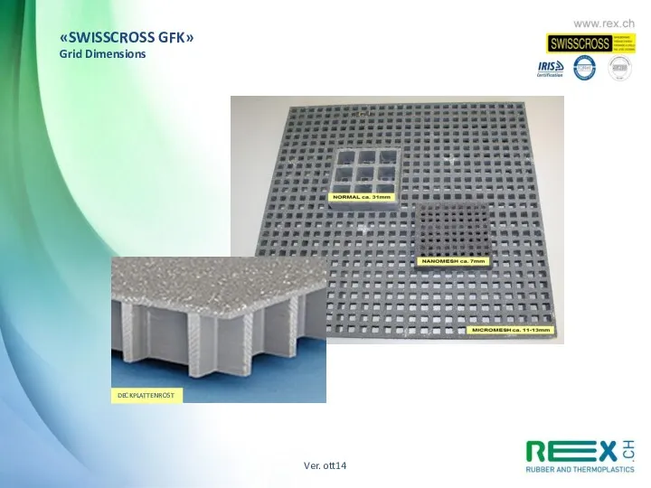
- 43. DECKPLATTENROST Ver. ott14 «SWISSCROSS GFK» Grid Dimensions
- 44. Ver. ott14
- 46. Скачать презентацию
Rail & Road – Technique ferroviaire August 2014
Ver. ott14
«SWISSCROSS RUBE»
RUBBER-CONCRETE
LEVEL
Rail & Road – Technique ferroviaire August 2014
Ver. ott14
«SWISSCROSS RUBE»
RUBBER-CONCRETE
LEVEL
Advantages
Best vibration damping and noise reduction
More Load resistance and less deformation
Advantages
Best vibration damping and noise reduction
More Load resistance and less deformation
Ver. ott14
Rubber-concrete level crossing
«SWISSCROSS RUBE»
gauge: 1000 – 1435 – 1524
Ver. ott14
Rubber-concrete level crossing
«SWISSCROSS RUBE»
gauge: 1000 – 1435 – 1524
INSTALLATION INSTRUCTION FOR SWISSCROSS PASSAGE AT RUBE
1. USE
This statement relates to
INSTALLATION INSTRUCTION FOR SWISSCROSS PASSAGE AT RUBE
1. USE
This statement relates to

RUBE 1000 with side elements in rubber
RUBE 1435 with side elements
RUBE 1435 with side elements
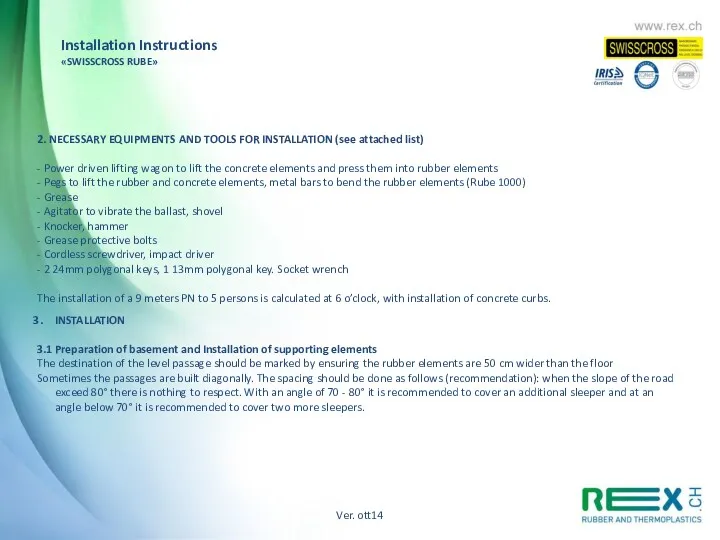
2. NECESSARY EQUIPMENTS AND TOOLS FOR INSTALLATION (see attached list)
- Power
- Power
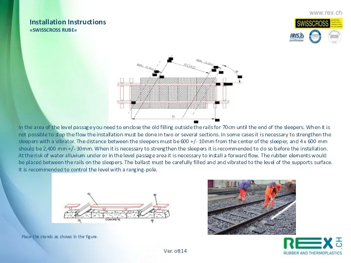
In the area of the level passage you need to enclose
In the area of the level passage you need to enclose
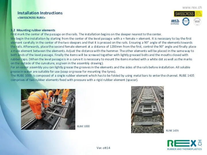
3.2 Mounting rubber elements
First mark the center of the passage on
3.2 Mounting rubber elements
First mark the center of the passage on
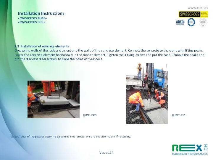
3.3 Installation of concrete elements
Grease the walls of the rubber element
3.3 Installation of concrete elements
Grease the walls of the rubber element
Ver. ott14
Installation Instructions
«SWISSCROSS RUBE»
«SWISSCROSS H.D.»
Ver. ott14
Installation Instructions
«SWISSCROSS RUBE»
«SWISSCROSS H.D.»
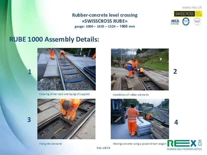
RUBE 1000 Assembly Details:
1
2
4
3
Cleaning of the track and laying of supports
Installation
RUBE 1000 Assembly Details:
1
2
4
3
Cleaning of the track and laying of supports
Installation
5
6
7
Place concrete elements in rubber
Place concrete elements to rubber
Installing of accessories
Installing
5
6
7
Place concrete elements in rubber
Place concrete elements to rubber
Installing of accessories
Installing
1
2
3
4
RUBE 1435-1524-1600 Assembly Details:
Cleaning of the track and installation of supports
Laying
1
2
3
4
RUBE 1435-1524-1600 Assembly Details:
Cleaning of the track and installation of supports
Laying
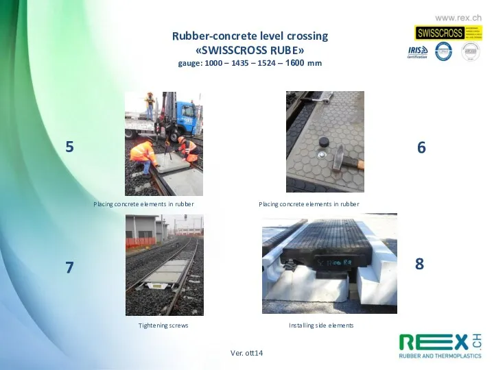
5
6
7
8
Placing concrete elements in rubber
Placing concrete elements in rubber
Tightening screws
Installing side
5
6
7
8
Placing concrete elements in rubber
Placing concrete elements in rubber
Tightening screws
Installing side
RAMS : PL Rube 1000-1435
Description of the system in which the
RAMS : PL Rube 1000-1435 Description of the system in which the
RAMS : PL Rube 1000-1435
Description of the environnement in which the
RAMS : PL Rube 1000-1435
Description of the environnement in which the
RAMS : PL Rube 1000-1435
Reliability :
The Swisscross Rube level passage is
RAMS : PL Rube 1000-1435
Reliability :
The Swisscross Rube level passage is
RAMS : PL Rube 1000-1435
Security
For the installation of the Swisscross
RAMS : PL Rube 1000-1435
Security
For the installation of the Swisscross
RAMS : PL Rube 1000-1435
Availability
Swisscross ensures the supply of wear
RAMS : PL Rube 1000-1435
Availability
Swisscross ensures the supply of wear
RAMS : PL Rube 1000-1435
Handling, packaging , transport and storage
Handling
RAMS : PL Rube 1000-1435
Handling, packaging , transport and storage
Handling
RAMS : PL Rube 1000-1435
Disposal of waste:
The rubber elements must
RAMS : PL Rube 1000-1435
Disposal of waste:
The rubber elements must
«SWISSCROSS RUBE WITH SIDE ELEMENT IN RUBBER-CONCRETE»
PROTOTYPE 2014
The new model Swisscross
«SWISSCROSS RUBE WITH SIDE ELEMENT IN RUBBER-CONCRETE»
PROTOTYPE 2014
The new model Swisscross
Ver. ott14
«SWISSCROSS RUBE»
Tipologies
Ver. ott14
«SWISSCROSS RUBE»
Tipologies
Ver. ott14
«SWISSCROSS RUBE»
Check List
Ver. ott14
«SWISSCROSS RUBE»
Check List
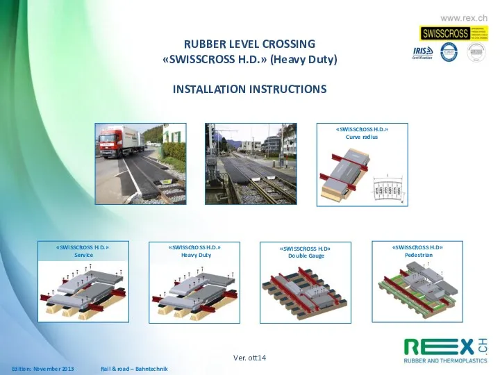
Rail & road – Bahntechnik
«SWISSCROSS H.D.»
Curve radius
«SWISSCROSS H.D.»
Service
«SWISSCROSS H.D.»
Heavy
Rail & road – Bahntechnik
«SWISSCROSS H.D.»
Curve radius
«SWISSCROSS H.D.»
Service
«SWISSCROSS H.D.»
Heavy
INSTALLATION INSTRUCTIONS
APPLICATION
2. REQUIRED EQUIPMENT AND TOOLS
3. ASSEMBLY
3.1 Ground preparation
3.2
APPLICATION
2. REQUIRED EQUIPMENT AND TOOLS
3. ASSEMBLY
3.1 Ground preparation
3.2
1. APPLICATION
This assembly guide applies to the “SWISSCROSS H.D“ rubber railroad
1. APPLICATION
This assembly guide applies to the “SWISSCROSS H.D“ rubber railroad
Around the crossing, 70 cm of the old surface outside of
Around the crossing, 70 cm of the old surface outside of
«SWISSCROSS H.D.»
Assembly guide gauge 1000, 1435 und 1524mm
The other elements
«SWISSCROSS H.D.»
Assembly guide gauge 1000, 1435 und 1524mm
The other elements
4.2 Detaching and reassembly of ”SWISSCROSS“ railroad crossings
These additional instructions have
4.2 Detaching and reassembly of ”SWISSCROSS“ railroad crossings
These additional instructions have
Ver. ott14
«SWISSCROSS H.D.»
Tipologies
Ver. ott14
«SWISSCROSS H.D.»
Tipologies
Ver. ott14
«SWISSCROSS H.D.»
Check List
Ver. ott14
«SWISSCROSS H.D.»
Check List
«SWISSCROSS GFK»
LEVEL CROSSING
«SWISSCROSS GFK»
PIT COVERING
«SWISSCROSS GFK»
SWITCH/POINT
«SWISSCROSS GFK»
«SWISSCROSS GFK»
LEVEL CROSSING
«SWISSCROSS GFK»
PIT COVERING
«SWISSCROSS GFK»
SWITCH/POINT
«SWISSCROSS GFK»
Ver. ott14
Service/pedestrian crossing
«SWISSCROSS GFK»
INSTALLATION INSTRUCTIONS
FIELD OF APPLICATION
2. TOOLS AND MATERIALS
Ver. ott14
Service/pedestrian crossing
«SWISSCROSS GFK»
INSTALLATION INSTRUCTIONS
FIELD OF APPLICATION
2. TOOLS AND MATERIALS
1. FIELD OF APPLICATION
These instructions apply to all SWISSCROSS GFK models
1. FIELD OF APPLICATION
These instructions apply to all SWISSCROSS GFK models
Identify the height of the load-bearing beam for the covering plates
Identify the height of the load-bearing beam for the covering plates
Place the covering plates on the supporting beams, according to the
Place the covering plates on the supporting beams, according to the
Covering plate assembly with special fixing elements, usually about 4 fixing/sqm,
Covering plate assembly with special fixing elements, usually about 4 fixing/sqm,
Installation instructions
«SWISSCROSS GFK»
5. ITEM ASSEMBLY
SECTION:
Sleeper: Wood – Cement - Steel
LEANING OUTER
Installation instructions
«SWISSCROSS GFK»
5. ITEM ASSEMBLY
SECTION:
Sleeper: Wood – Cement - Steel
LEANING OUTER

Installation instructions
«SWISSCROSS GFK»
5. ITEM ASSEMBLY
Ver. ott14
Installation instructions
«SWISSCROSS GFK»
5. ITEM ASSEMBLY
Ver. ott14
Ver. ott14
«SWISSCROSS GFK»
Check List
Ver. ott14
«SWISSCROSS GFK»
Check List
DECKPLATTENROST
Ver. ott14
«SWISSCROSS GFK»
Grid Dimensions
DECKPLATTENROST
Ver. ott14
«SWISSCROSS GFK»
Grid Dimensions
Ver. ott14
Ver. ott14
 От Коперника до наших дней
 Баскетбол. История игры и правила игры
 Т_Digestive tract, L5
 Управление процессами поддержания летной годности воздушных судов
 Россия весной-летом 1917 года
 Уроки этикета.
 Гиперактивный ребенок.
 Вторая мировая война
 Напівпровідники. P-n перехід і його електричні властивості
 Несплошности в теле отливки
 Теплоэнергетика технологии обжига известняка во вращающихся печах
 Compressed elements of constant cross section. Compressed transition elements of constant cross section
 Net Framework - платформа разработки, для создания приложений для Windows, Windows Phone, Windows Server и Microsoft Azure
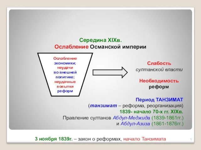 Танзимат. Середина XIXв. Ослабление Османской империи
 Родительское собрание
 Презентация Интегрированный урок - как средство формирования позитивной мотивации в обучении школьников
 От героев былых времен... Презентация для классного часа
 Самостоятельные и служебные части речи
 Поэтический конкурс, посвящённый 80-летию поэта Николая Рубцова
 Дидактика - как наука об обучении
 Правила поведения учащихся в школе и на улице.
 Водная оболочка Земли – гидросфера
 Политическая экономия современного капитализма: неомарксистский синтез и его задачи
 Презентация ЗИМНЯЯ ОДЕЖДА
 Численность населения России. Презентация.
 Классификация материалов, применяемых в обойных работах
 Определение размеров элементов и конструкций столярных изделий. (Тема 12)
 Презентация-викторина День защитников Отечества