- TPMS Introduction (v.2)

Содержание
- 2. TPMS Pressure-Sensor Based TPMS(shorten for:PSB TPMS, or directness type TPMS),namely this system monitors tyre pressure by
- 3. When vehicle speed exceeds 20Km/h,type pressure sensor begins to work. When vehicle stops for 10 minutes,
- 4. Schematic Diagram
- 5. Circuit Diagram Sensor 1 Sensor 2 Sensor 3 Sensor 4 ground Rear mirror ground power Diagnosis
- 6. ● Warning Function ► tyre pressure low:25 % lower than standard value ► tyre pressure high:
- 7. Tyre pressure sensor Pressure receiver Rear mirror System Component
- 8. air valve bonnet Rubber washer bolt Tyre pressure monitor emitter The sensor is mounted inside each
- 9. Location: don’t forget tyre balance operationg before mounting
- 10. Sensor Mount ① screw down nut, then mount air valve nozzle through wheel hub hole ②
- 11. After mount, do tyre balance operation.
- 12. receiver Receiver Location
- 13. Ⅰ. TPMS Initialization Operation Guide Ⅱ. Replace tyre pressure sensor Ⅲ. Tyre rotation Ⅳ. Lin bus
- 14. TPMS Program Tool DC-9V BMG TPMS Program Tool MODEL:3641130-K80 INPUT:DC 9V 434MHz SN:CHADXXXXXXXXX Laser print
- 15. TPMS Program Tool Tyre position Enter Tyre position indicator Function indicator Function button switch Parameter: 1.dimension:
- 16. Function Button ★ ★ ★
- 17. Initialization ( for user who add the system after bought can use this function ) ATTN:
- 18. 1.2 put TPMS program tool close to tyre valve nib within 50 cm to set sensor
- 19. 1.3 then register the other tyre position, of course, the lamps will keep on after register.
- 20. 1.5 after 4 tyre indicating lamps light on, put TPMS program tool close to the receiver
- 21. Receiver
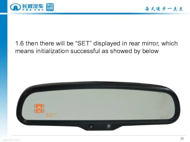
- 22. 1.6 then there will be “SET” displayed in rear mirror, which means initialization successful as showed
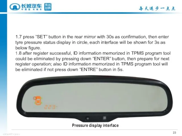
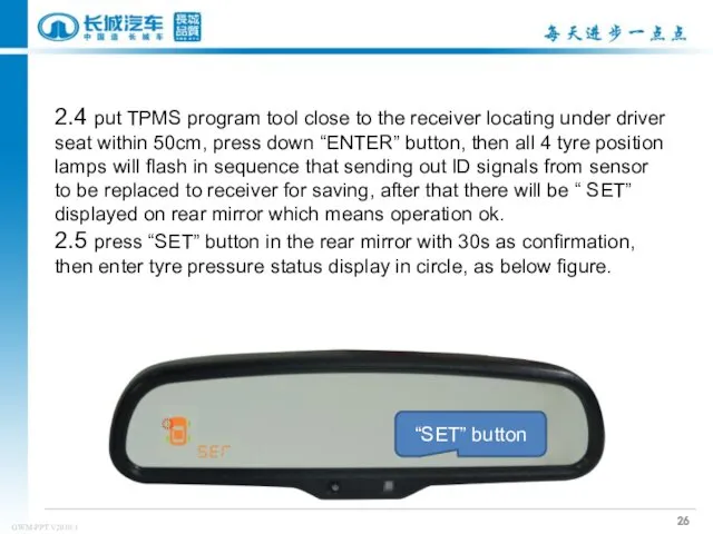
- 23. 1.7 press “SET” button in the rear mirror with 30s as confirmation, then enter tyre pressure
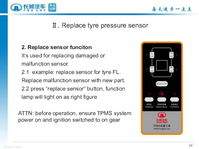
- 24. 2. Replace sensor funciton It’s used for replacing damaged or malfunction sensor. 2.1 example: replace sensor
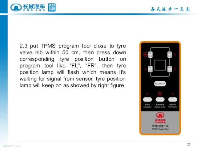
- 25. 2.3 put TPMS program tool close to tyre valve nib within 50 cm, then press down
- 26. 2.4 put TPMS program tool close to the receiver locating under driver seat within 50cm, press
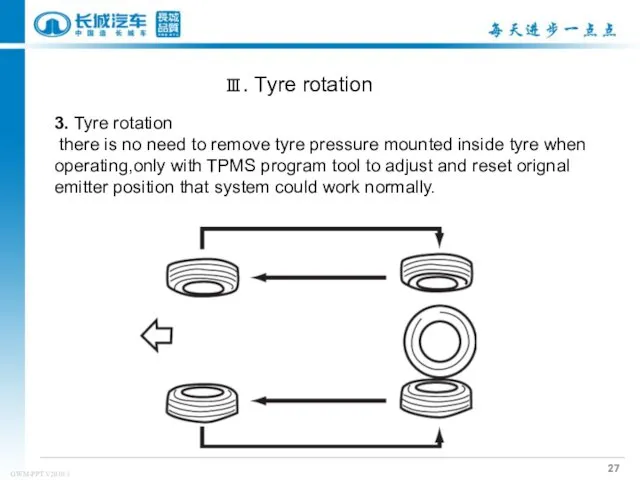
- 27. 3. Tyre rotation there is no need to remove tyre pressure mounted inside tyre when operating,only
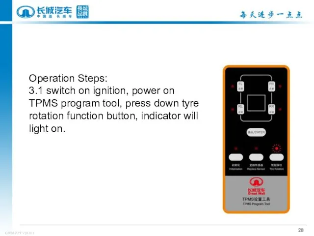
- 28. Operation Steps: 3.1 switch on ignition, power on TPMS program tool, press down tyre rotation function
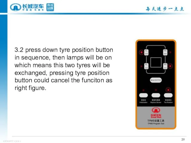
- 29. 3.2 press down tyre position button in sequence, then lamps will be on which means this
- 30. 3.3After selecting tyres to be exchanged each other, put TPMS program tool close to the receiver
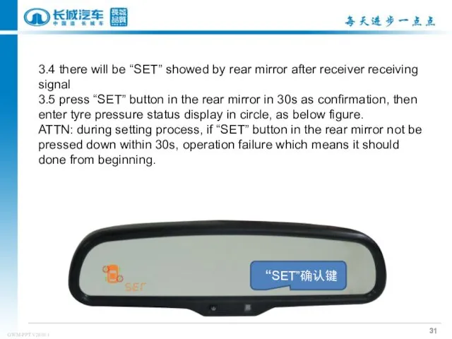
- 31. 3.4 there will be “SET” showed by rear mirror after receiver receiving signal 3.5 press “SET”
- 32. in case when receiver and Lin line or IGN power line malfunction, rear mirror will entre
- 34. Скачать презентацию
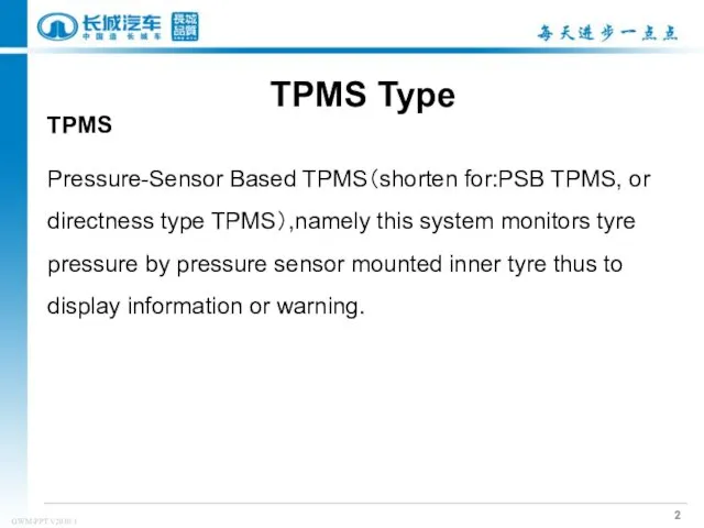
TPMS
Pressure-Sensor Based TPMS(shorten for:PSB TPMS, or directness type TPMS),namely this system
TPMS
Pressure-Sensor Based TPMS(shorten for:PSB TPMS, or directness type TPMS),namely this system
When vehicle speed exceeds 20Km/h,type pressure sensor begins to work.
When vehicle speed exceeds 20Km/h,type pressure sensor begins to work.
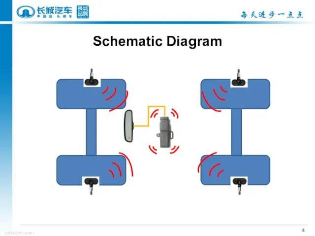
Schematic Diagram
Schematic Diagram
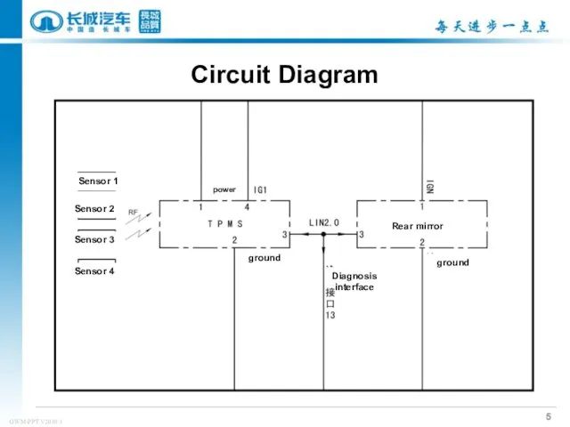
Circuit Diagram
Sensor 1
Sensor 2
Sensor 3
Sensor 4
ground
Rear mirror
ground
power
Diagnosis interface
Circuit Diagram
Sensor 1
Sensor 2
Sensor 3
Sensor 4
ground
Rear mirror
ground
power
Diagnosis interface
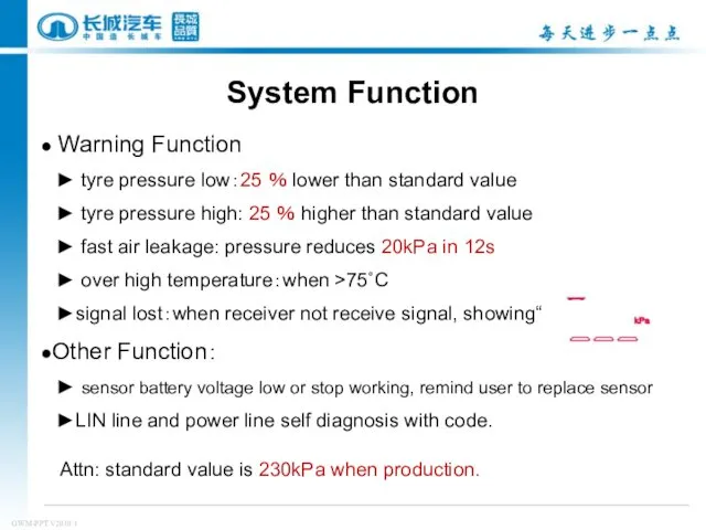
● Warning Function
► tyre pressure low:25 % lower than standard
● Warning Function
► tyre pressure low:25 % lower than standard
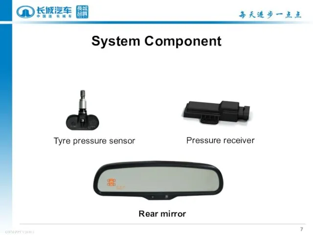
Tyre pressure sensor
Pressure receiver
Rear mirror
System Component
Tyre pressure sensor
Pressure receiver
Rear mirror
System Component
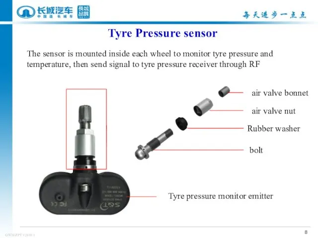
air valve bonnet
Rubber washer
bolt
Tyre pressure monitor emitter
The sensor is mounted
air valve bonnet
Rubber washer
bolt
Tyre pressure monitor emitter
The sensor is mounted
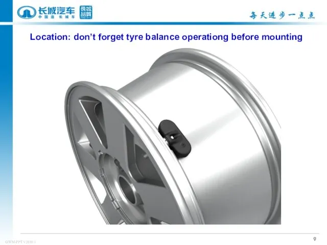
Location: don’t forget tyre balance operationg before mounting
Location: don’t forget tyre balance operationg before mounting
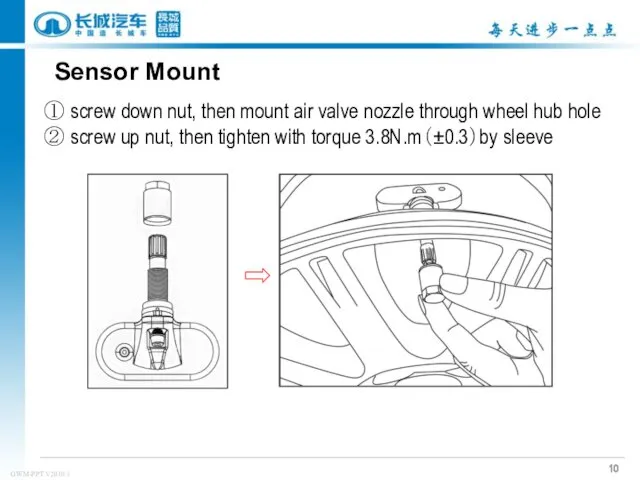
Sensor Mount
① screw down nut, then mount air valve nozzle through
Sensor Mount
① screw down nut, then mount air valve nozzle through
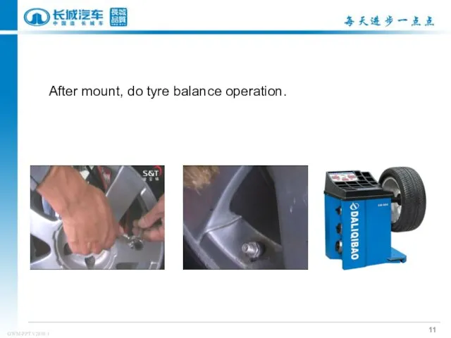
After mount, do tyre balance operation.
After mount, do tyre balance operation.
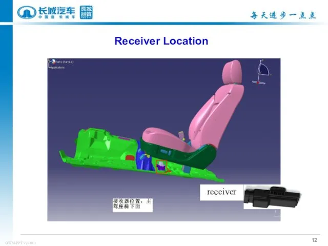
receiver
Receiver Location
receiver
Receiver Location
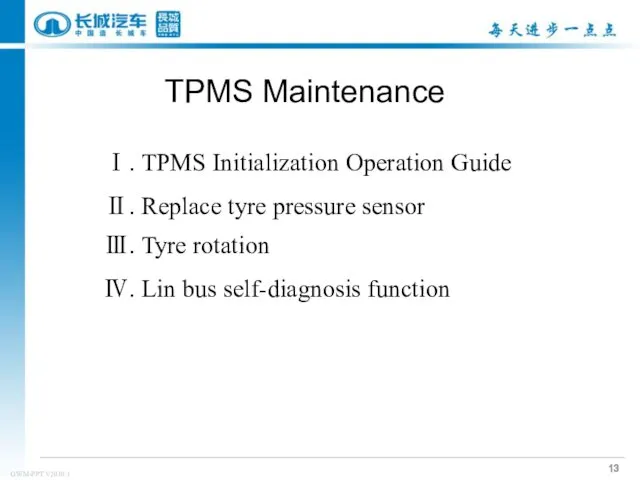
Ⅰ. TPMS Initialization Operation Guide
Ⅱ. Replace tyre pressure sensor
Ⅲ. Tyre rotation
Ⅳ.
Ⅰ. TPMS Initialization Operation Guide
Ⅱ. Replace tyre pressure sensor
Ⅲ. Tyre rotation
Ⅳ.
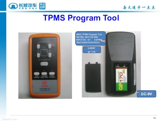
TPMS Program Tool
DC-9V
BMG TPMS Program Tool
MODEL:3641130-K80
INPUT:DC 9V 434MHz
SN:CHADXXXXXXXXX
Laser print
TPMS Program Tool
DC-9V
BMG TPMS Program Tool
MODEL:3641130-K80
INPUT:DC 9V 434MHz
SN:CHADXXXXXXXXX
Laser print
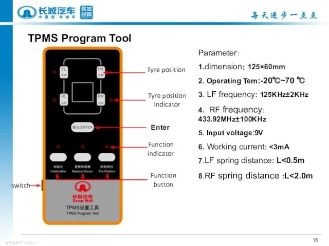
TPMS Program Tool
Tyre position
Enter
Tyre position
indicator
Function
indicator
Function
button
switch
Parameter:
1.dimension: 125×60mm
2. Operating Tem:-20℃~70
TPMS Program Tool
Tyre position
Enter
Tyre position
indicator
Function
indicator
Function
button
switch
Parameter:
1.dimension: 125×60mm
2. Operating Tem:-20℃~70
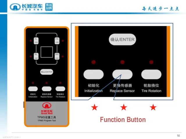
Function Button
★
★
★
Function Button
★
★
★
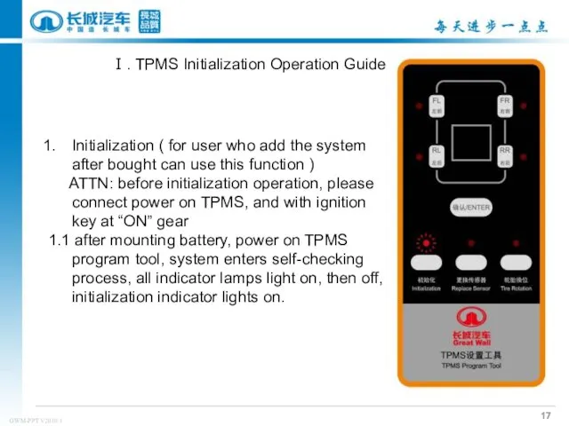
Initialization ( for user who add the system after bought can
Initialization ( for user who add the system after bought can
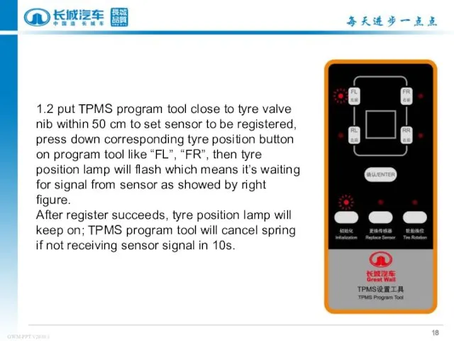
1.2 put TPMS program tool close to tyre valve nib within
1.2 put TPMS program tool close to tyre valve nib within
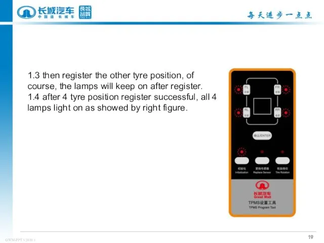
1.3 then register the other tyre position, of course, the lamps
1.3 then register the other tyre position, of course, the lamps
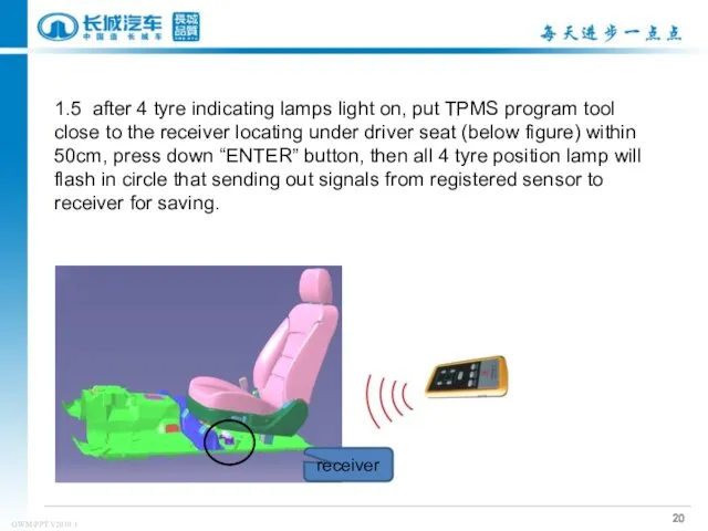
1.5 after 4 tyre indicating lamps light on, put TPMS program
1.5 after 4 tyre indicating lamps light on, put TPMS program
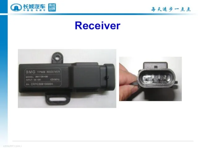
Receiver
Receiver
1.6 then there will be “SET” displayed in rear mirror, which
1.6 then there will be “SET” displayed in rear mirror, which
1.7 press “SET” button in the rear mirror with 30s as
1.7 press “SET” button in the rear mirror with 30s as
2. Replace sensor funciton
It’s used for replacing damaged or malfunction sensor.
2. Replace sensor funciton
It’s used for replacing damaged or malfunction sensor.
2.3 put TPMS program tool close to tyre valve nib within
2.3 put TPMS program tool close to tyre valve nib within
2.4 put TPMS program tool close to the receiver locating under
2.4 put TPMS program tool close to the receiver locating under
3. Tyre rotation
there is no need to remove tyre pressure
3. Tyre rotation
there is no need to remove tyre pressure
Operation Steps:
3.1 switch on ignition, power on TPMS program tool, press
Operation Steps:
3.1 switch on ignition, power on TPMS program tool, press
3.2 press down tyre position button in sequence, then lamps will
3.2 press down tyre position button in sequence, then lamps will
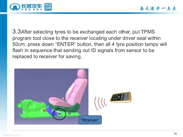
3.3After selecting tyres to be exchanged each other, put TPMS program
3.3After selecting tyres to be exchanged each other, put TPMS program
3.4 there will be “SET” showed by rear mirror after receiver
3.4 there will be “SET” showed by rear mirror after receiver
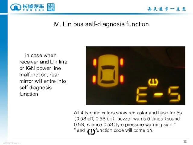
in case when receiver and Lin line or IGN power
in case when receiver and Lin line or IGN power
 Ветераны Великой Отечественной войны - сотрудники САФУ
 презентация к статье Использование технологии критического мышления на уроках чтения и окружающего мира.
 Подготовка кадрового состава для организаций отдыха и оздоровления детей в условиях педагогического вуза
 6.4. Системы управления оборудованием ТЗА
 Художественная культура России в XVIII веке
 Роль медицинской сестры в охране репродуктивного здоровья и планирования семьи
 Отдел продаж Skoda. Итоги за март 2018 года
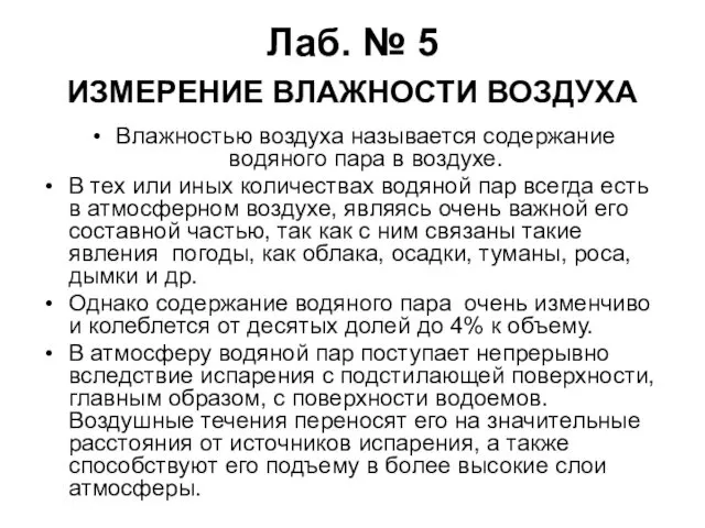 Измерение влажности воздуха
 Тибетский тест личности
 Дербес компьютер. Компьютердің құрылысы
 Закят: очищение имущества и залог процветания общества
 День знаний для 2 класса.
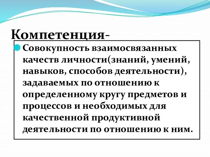 Компетенция в процессе обучения
 Образование, наука, техника и технологии. Методы научного познания
 Строительные грузы и их транспортировка
 Александр II Освободитель 1855-1881
 Нобелевская премия
 Пи́ттсбург Пи́нгвинз— профессиональный хоккейный клуб
 Основные виды дефектов, причины и способы их устранения
 Что такое текст? 5 класс
 Проектирование цифровых устройств на ПЛИС
 Основные положения и принципы клинической эпидемиологии, связь клинической эпидемиологии с биостатистикой
 Ингибиторы протонной помпы
 Использование русских народных и шумовых инструментов на праздниках и развлечениях в ДОУ.
 Количество вещества, число Авогадро, молярная масса, молярный объём, уравнение связи
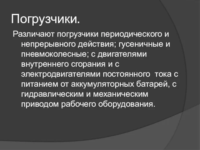 Погрузчики. Виды погрузчиков
 Краудфандинг - народное финансирование
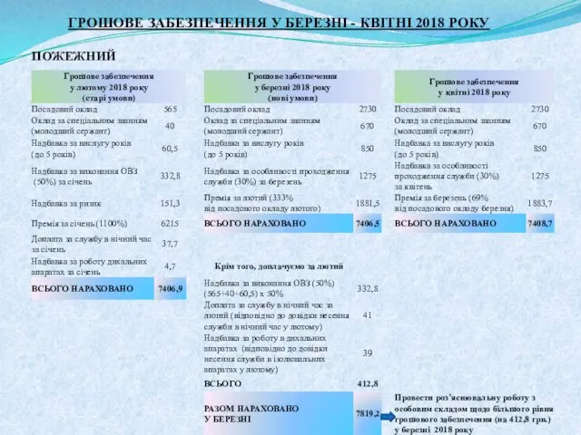 Грошове забезпечення у березні - квітні 2018 року