- Cathode Ray Oscilloscope

Содержание
- 2. What is an Oscilloscope? Oscilloscopes are very fast X-Y plotters, displaying an input signal versus time.
- 3. Block diagram of CRT oscilloscope
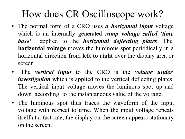
- 4. How does CR Oscilloscope work? The normal form of a CRO uses a horizontal input voltage
- 5. Construction of Cathode Ray Tube
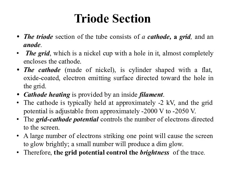
- 6. Triode Section The triode section of the tube consists of a cathode, a grid, and an
- 7. The first anode (A1) is cylinder shaped, open at one end and closed at the other
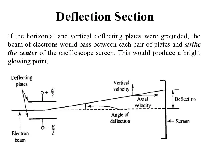
- 8. Deflection Section If the horizontal and vertical deflecting plates were grounded, the beam of electrons would
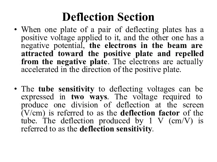
- 9. Deflection Section When one plate of a pair of deflecting plates has a positive voltage applied
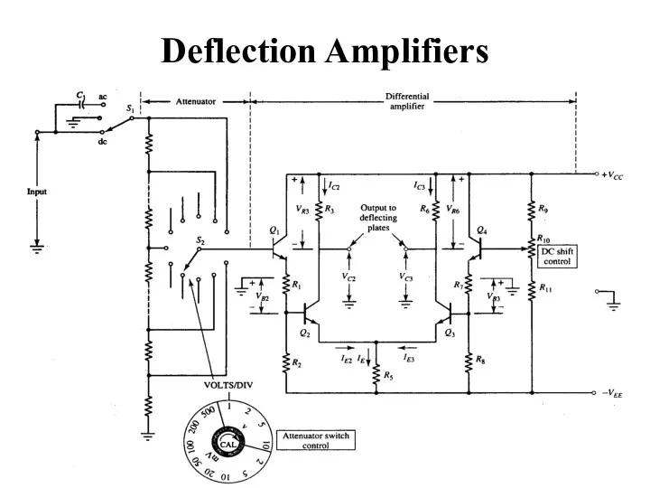
- 10. Deflection Amplifiers
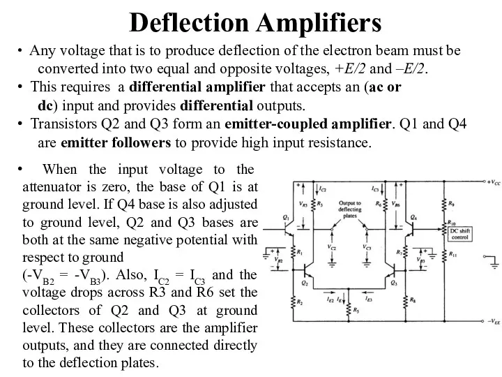
- 11. Deflection Amplifiers When the input voltage to the attenuator is zero, the base of Q1 is
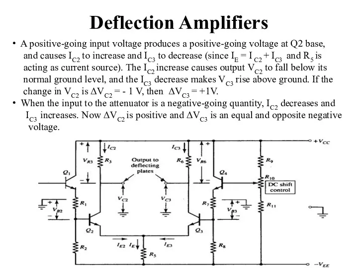
- 12. Deflection Amplifiers A positive-going input voltage produces a positive-going voltage at Q2 base, and causes IC2
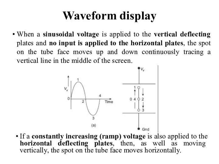
- 13. Waveform display If a constantly increasing (ramp) voltage is also applied to the horizontal deflecting plates,
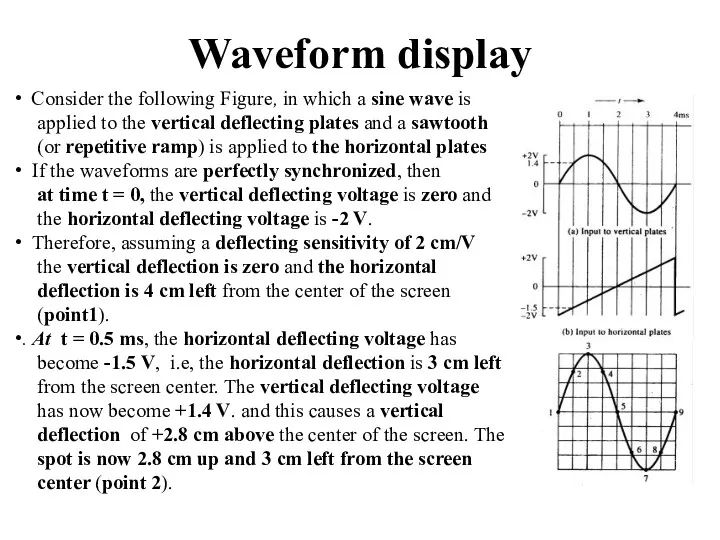
- 14. Waveform display Consider the following Figure, in which a sine wave is applied to the vertical
- 15. Oscilloscope time base Horizontal Sweep Generator
- 16. Horizontal Sweep Generator The sweep generator consists of two major components: a ramp generator and a
- 17. Schmitt trigger circuit Because the op-amp has a very large voltage gain (typically 200000), a very
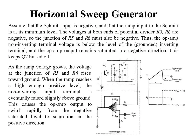
- 18. Horizontal Sweep Generator Assume that the Schmitt input is negative, and that the ramp input to
- 19. Automatic Time Base For a waveform to be displayed correctly on an oscilloscope, it is important
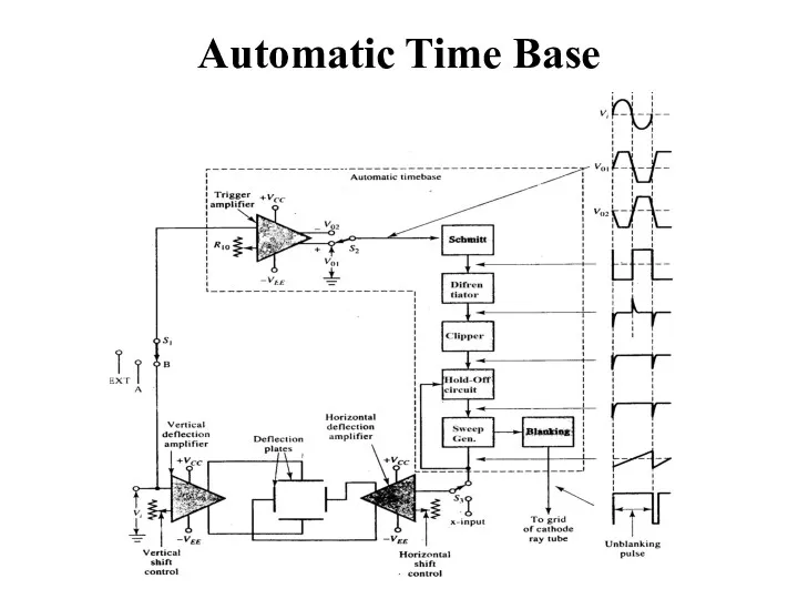
- 20. Automatic Time Base
- 21. Automatic Time Base The voltage waveform to be displayed (Vi) is applied to the vertical amplifier
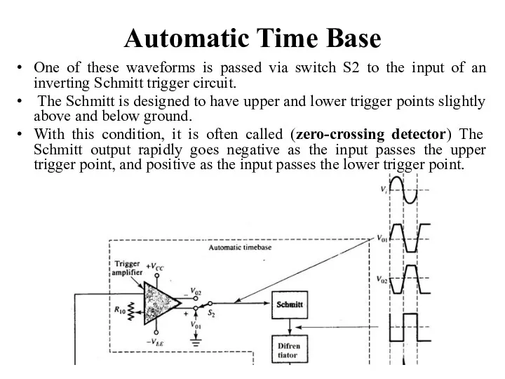
- 22. Automatic Time Base One of these waveforms is passed via switch S2 to the input of
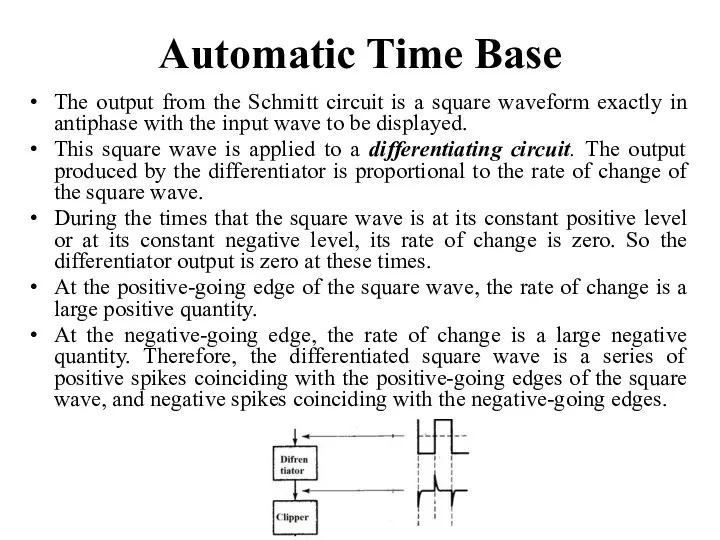
- 23. Automatic Time Base The output from the Schmitt circuit is a square waveform exactly in antiphase
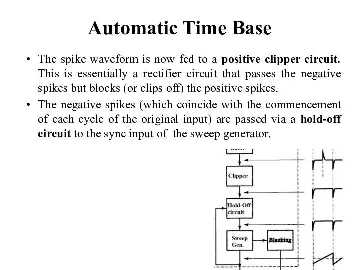
- 24. Automatic Time Base The spike waveform is now fed to a positive clipper circuit. This is
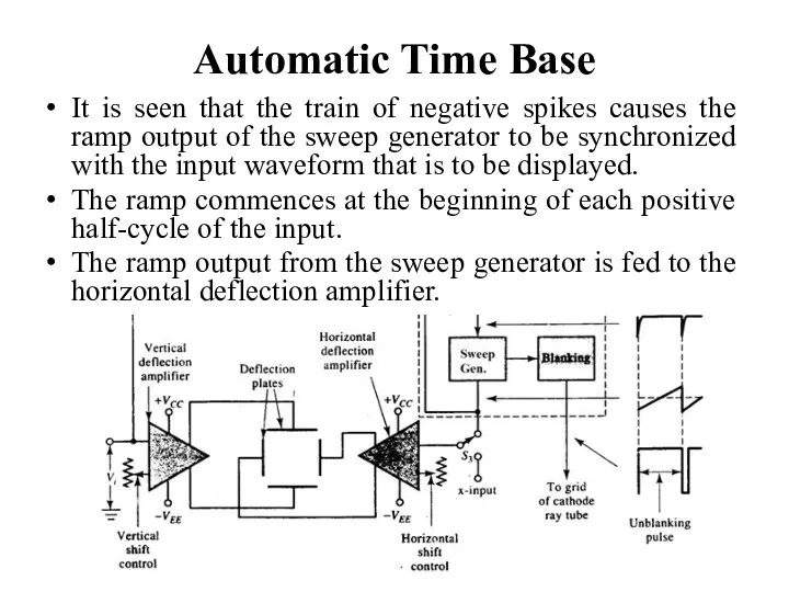
- 25. Automatic Time Base It is seen that the train of negative spikes causes the ramp output
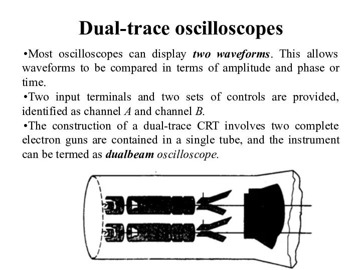
- 26. Dual-trace oscilloscopes Most oscilloscopes can display two waveforms. This allows waveforms to be compared in terms
- 27. Dual-trace oscilloscopes In another type of dual-trace CRT, a single electron gun is involved, but the
- 28. Dual-trace oscilloscopes Another common type of dual trace oscilloscope is (the switched single beam). A single-beam
- 29. Oscilloscope control switches
- 30. Measurement of Voltage The peak-to-peak amplitude of a displayed waveform is very easily measured on an
- 31. Measurement of Voltage Waveform A has a peak-to-peak amplitude of 4.6 vertical divisions on the screen,
- 32. Frequency Determination The time period of a sine wave is determined by measuring the time for
- 34. Скачать презентацию
What is an Oscilloscope?
Oscilloscopes are very fast X-Y plotters, displaying an
What is an Oscilloscope?
Oscilloscopes are very fast X-Y plotters, displaying an
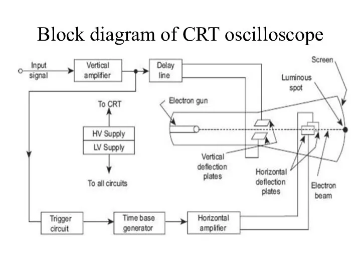
Block diagram of CRT oscilloscope
Block diagram of CRT oscilloscope
How does CR Oscilloscope work?
The normal form of a CRO uses
How does CR Oscilloscope work?
The normal form of a CRO uses
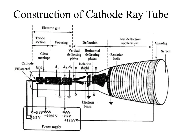
Construction of Cathode Ray Tube
Construction of Cathode Ray Tube
Triode Section
The triode section of the tube consists of a cathode,
Triode Section
The triode section of the tube consists of a cathode,
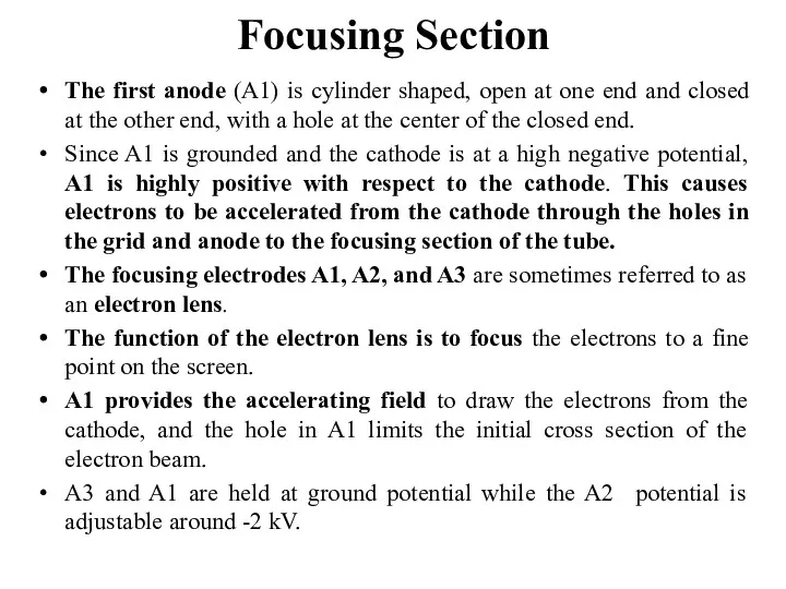
The first anode (A1) is cylinder shaped, open at one end
The first anode (A1) is cylinder shaped, open at one end
Deflection Section
If the horizontal and vertical deflecting plates were grounded, the
Deflection Section
If the horizontal and vertical deflecting plates were grounded, the
Deflection Section
When one plate of a pair of deflecting plates has
Deflection Section
When one plate of a pair of deflecting plates has
Deflection Amplifiers
Deflection Amplifiers
Deflection Amplifiers
When the input voltage to the attenuator is zero,
Deflection Amplifiers
When the input voltage to the attenuator is zero,
Deflection Amplifiers
A positive-going input voltage produces a positive-going voltage at
Deflection Amplifiers
A positive-going input voltage produces a positive-going voltage at
Waveform display
If a constantly increasing (ramp) voltage is also applied to
Waveform display
If a constantly increasing (ramp) voltage is also applied to
Waveform display
Consider the following Figure, in which a sine wave
Waveform display
Consider the following Figure, in which a sine wave
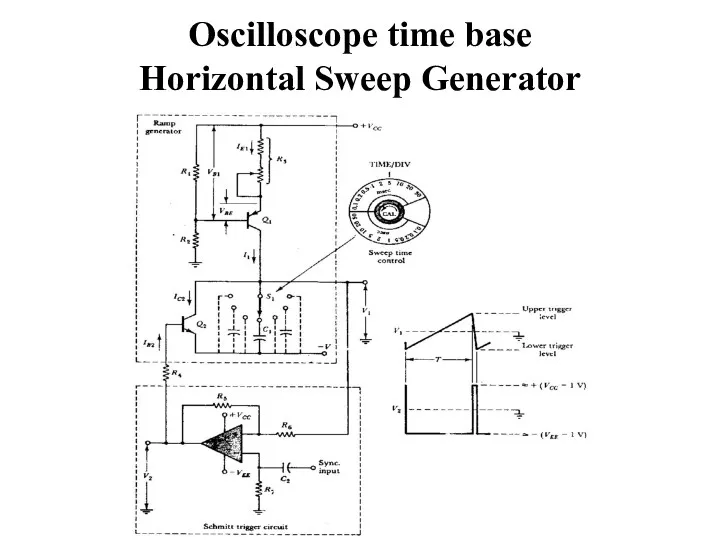
Oscilloscope time base
Horizontal Sweep Generator
Oscilloscope time base
Horizontal Sweep Generator
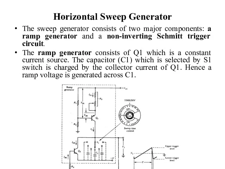
Horizontal Sweep Generator
The sweep generator consists of two major components:
Horizontal Sweep Generator
The sweep generator consists of two major components:
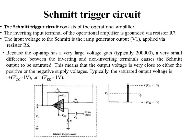
Schmitt trigger circuit
Because the op-amp has a very large voltage gain
Schmitt trigger circuit
Because the op-amp has a very large voltage gain
Horizontal Sweep Generator
Assume that the Schmitt input is negative, and
Horizontal Sweep Generator
Assume that the Schmitt input is negative, and
Automatic Time Base
For a waveform to be displayed correctly on an
Automatic Time Base
For a waveform to be displayed correctly on an
Automatic Time Base
Automatic Time Base

Automatic Time Base
The voltage waveform to be displayed (Vi) is applied
Automatic Time Base
The voltage waveform to be displayed (Vi) is applied
Automatic Time Base
One of these waveforms is passed via switch S2
Automatic Time Base
One of these waveforms is passed via switch S2
Automatic Time Base
The output from the Schmitt circuit is a square
Automatic Time Base
The output from the Schmitt circuit is a square
Automatic Time Base
The spike waveform is now fed to a positive
Automatic Time Base
The spike waveform is now fed to a positive
Automatic Time Base
It is seen that the train of negative spikes
Automatic Time Base
It is seen that the train of negative spikes
Dual-trace oscilloscopes
Most oscilloscopes can display two waveforms. This allows waveforms to
Dual-trace oscilloscopes
Most oscilloscopes can display two waveforms. This allows waveforms to
Dual-trace oscilloscopes
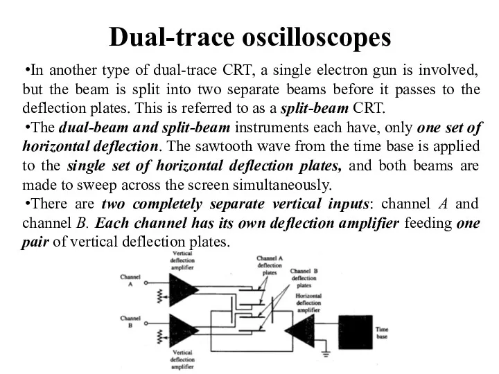
In another type of dual-trace CRT, a single electron gun
Dual-trace oscilloscopes
In another type of dual-trace CRT, a single electron gun
Dual-trace oscilloscopes
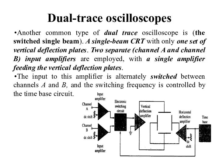
Another common type of dual trace oscilloscope is (the switched
Dual-trace oscilloscopes
Another common type of dual trace oscilloscope is (the switched
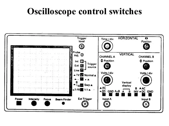
Oscilloscope control switches
Oscilloscope control switches
Measurement of Voltage
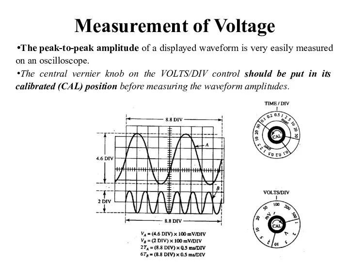
The peak-to-peak amplitude of a displayed waveform is very
Measurement of Voltage
The peak-to-peak amplitude of a displayed waveform is very
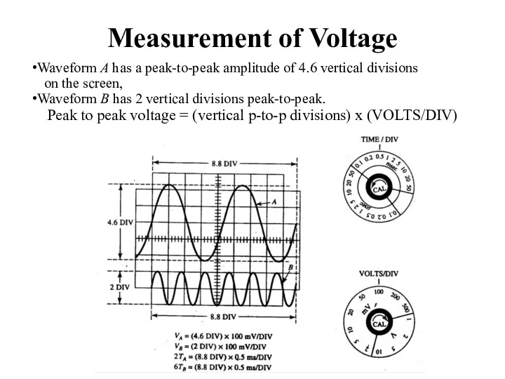
Measurement of Voltage
Waveform A has a peak-to-peak amplitude of 4.6 vertical
Measurement of Voltage
Waveform A has a peak-to-peak amplitude of 4.6 vertical
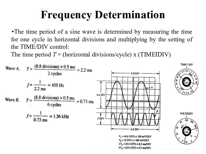
Frequency Determination
The time period of a sine wave is determined by
Frequency Determination
The time period of a sine wave is determined by
 Правила подготовки механических циферблатных весов к работе
 Свеча на воде (задача)
 Измерение основных электрических величин
 Что изучает физика
 Магнитное поле
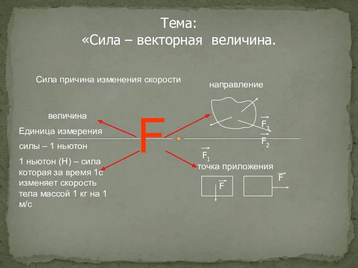 Сила – векторная величина
 Механизмы управления РУ и ТС
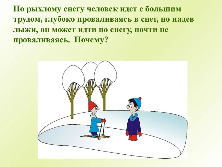 Давление
 Теплотехника. Недостатки поршневых ДВС. (Лекция 9)
 Молекулярно-кинетическая теория газов. (Лекция 2)
 Новые технологические процессы
 Электролиз
 Действия электрического тока
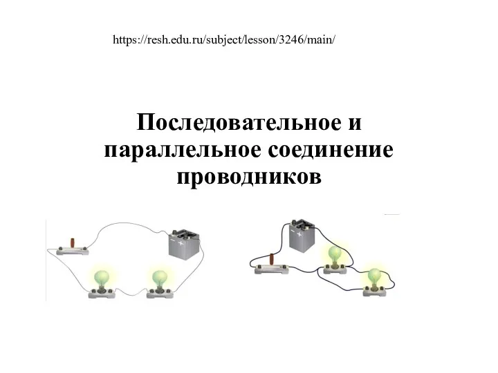 8Последовательное и параллельное соединение проводников
 Механическая работа. Связь между работой и скоростью движения тела
 Люди нашего края
 урок по физике (8 класс) по теме: ПАРАЛЛЕЛЬНОЕ СОЕДИНЕНИЕ ПРОВОДНИКОВ
 Динамика вращательного движения
 Выращивание кристаллов в домашних условиях
 Физика – наука о природе
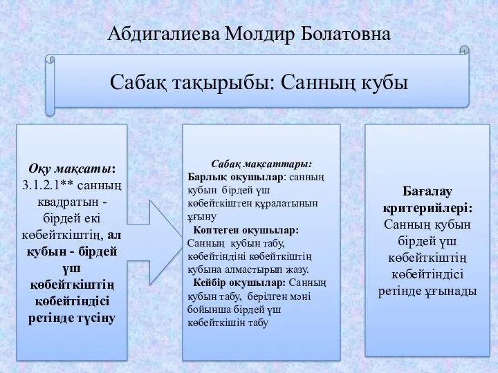 Санның кубы
 Деление атомных ядер. (Тема 2.7)
 7 компонентов, благодаря которым Ponsse Ergo является лучшим харвестером в своем классе размеров
 Применение методов флуоресцентных зондов для исследования белковых комплексов
 Источники света (презентация)
 презентация для 7 класс Определение цены деления прибора
 Закон Ома для полной цепи
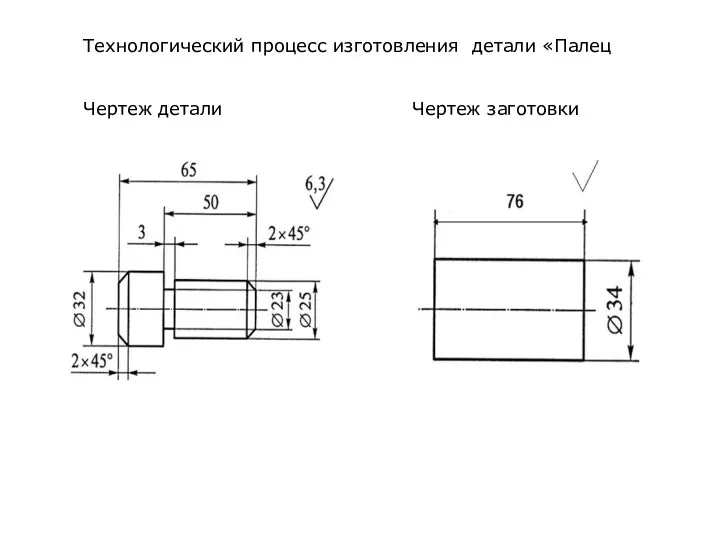 Изготовление деталей болт и гайка. Чертеж детали. Чертеж заготовки