- Europe Avensis

Содержание
- 2. 10/02/2022 Footer detail Contents Clutch EA6# Manual Transaxle EB60 / EC60 Manual Transaxle Gear Shift Indicator
- 3. 10/02/2022 Footer detail Clutch Subtitle
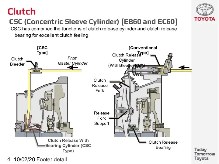
- 4. 10/02/2022 Footer detail Clutch CSC (Concentric Sleeve Cylinder) [EB60 and EC60] CSC has combined the functions
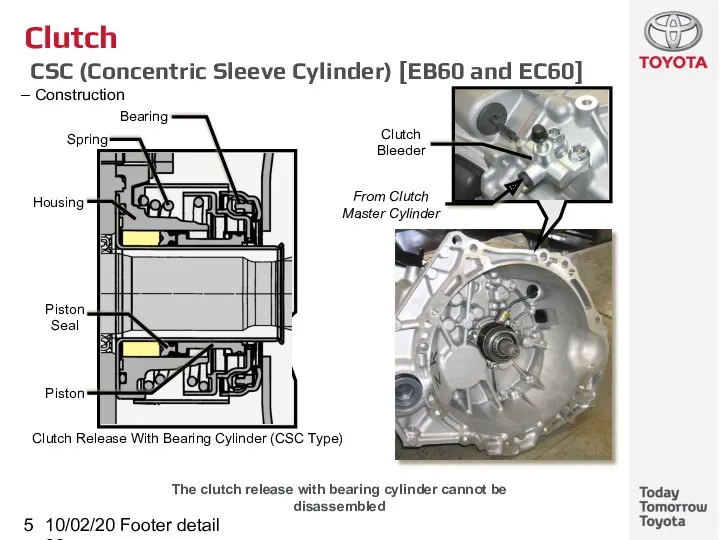
- 5. 10/02/2022 Footer detail Clutch CSC (Concentric Sleeve Cylinder) [EB60 and EC60] Construction The clutch release with
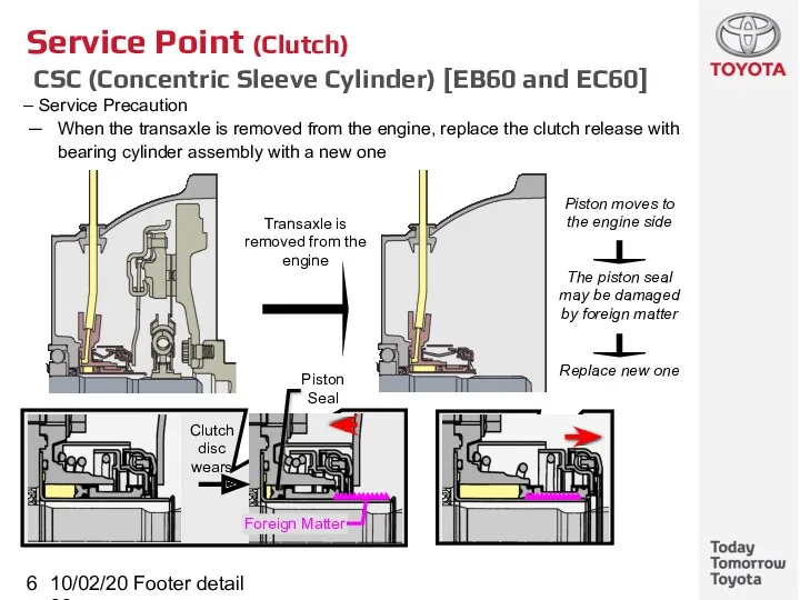
- 6. 10/02/2022 Footer detail Service Point (Clutch) CSC (Concentric Sleeve Cylinder) [EB60 and EC60] Service Precaution When
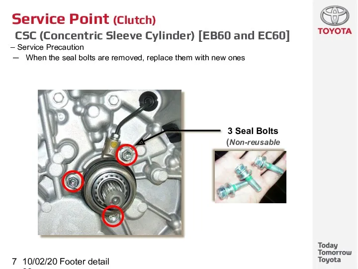
- 7. 10/02/2022 Footer detail Service Point (Clutch) CSC (Concentric Sleeve Cylinder) [EB60 and EC60] Service Precaution When
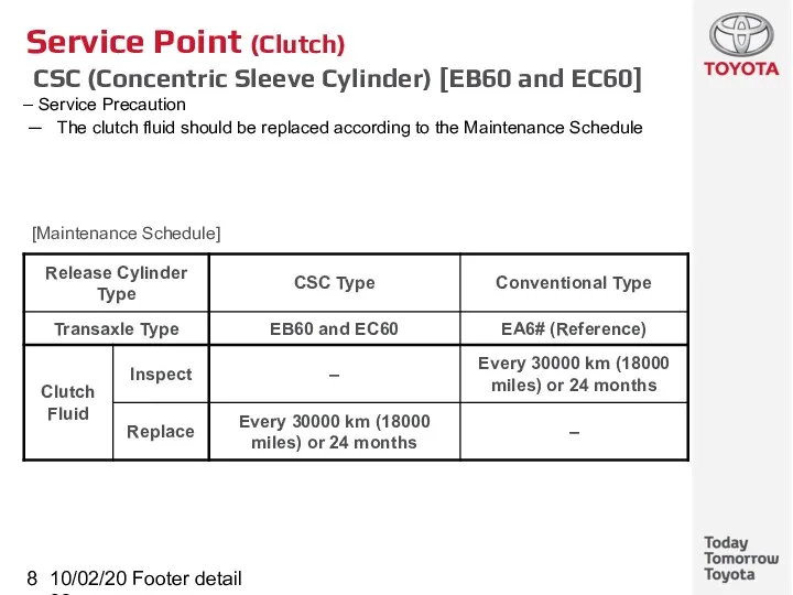
- 8. 10/02/2022 Footer detail Service Point (Clutch) CSC (Concentric Sleeve Cylinder) [EB60 and EC60] Service Precaution The
- 9. 10/02/2022 Footer detail EA6# Manual Transaxle Subtitle
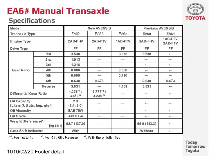
- 10. 10/02/2022 Footer detail EA6# Manual Transaxle Specifications *1: For 1st to 4th *2: For 5th, 6th,
- 11. 10/02/2022 Footer detail EB60 / EC60 Manual Transaxle Subtitle
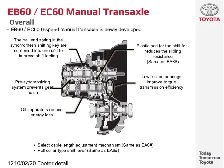
- 12. 10/02/2022 Footer detail EB60 / EC60 Manual Transaxle Overall EB60 / EC60 6-speed manual transaxle is
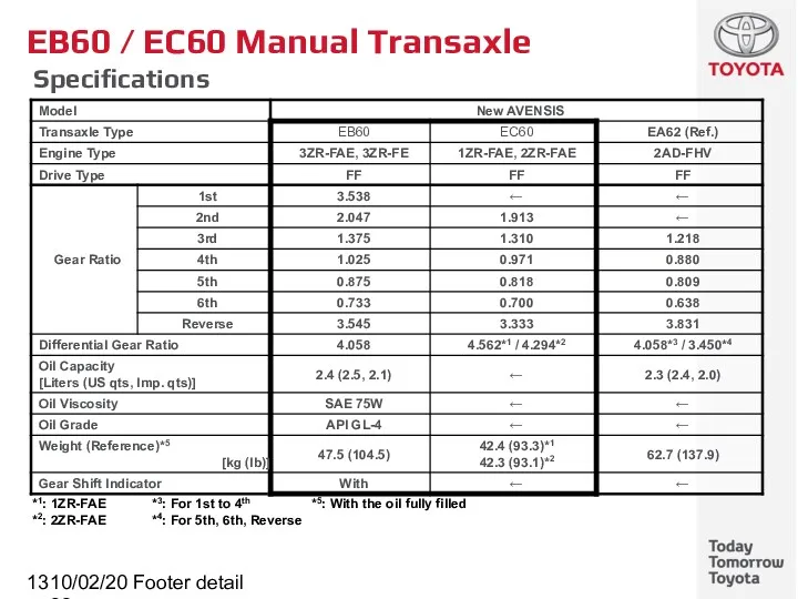
- 13. 10/02/2022 Footer detail EB60 / EC60 Manual Transaxle Specifications *1: 1ZR-FAE *3: For 1st to 4th
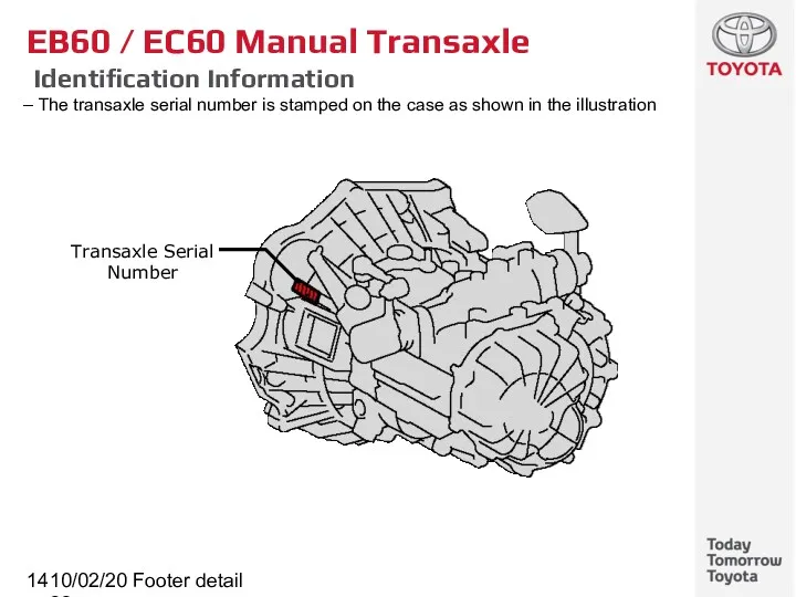
- 14. 10/02/2022 Footer detail EB60 / EC60 Manual Transaxle Identification Information The transaxle serial number is stamped
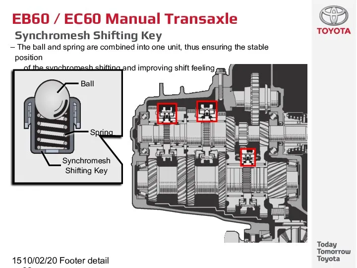
- 15. 10/02/2022 Footer detail EB60 / EC60 Manual Transaxle Synchromesh Shifting Key The ball and spring are
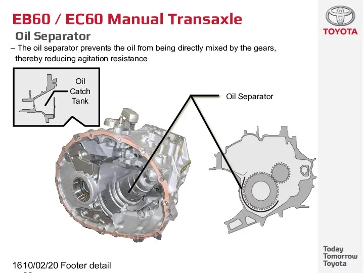
- 16. 10/02/2022 Footer detail EB60 / EC60 Manual Transaxle Oil Separator The oil separator prevents the oil
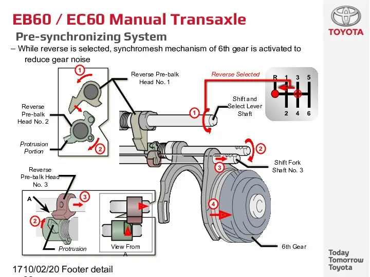
- 17. 10/02/2022 Footer detail EB60 / EC60 Manual Transaxle Pre-synchronizing System While reverse is selected, synchromesh mechanism
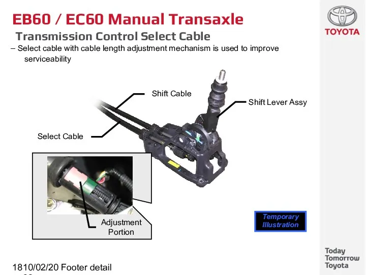
- 18. 10/02/2022 Footer detail EB60 / EC60 Manual Transaxle Transmission Control Select Cable Select cable with cable
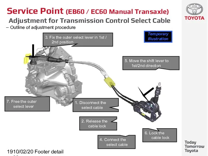
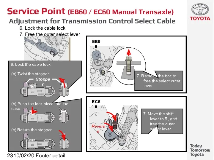
- 19. 10/02/2022 Footer detail Service Point (EB60 / EC60 Manual Transaxle) Adjustment for Transmission Control Select Cable
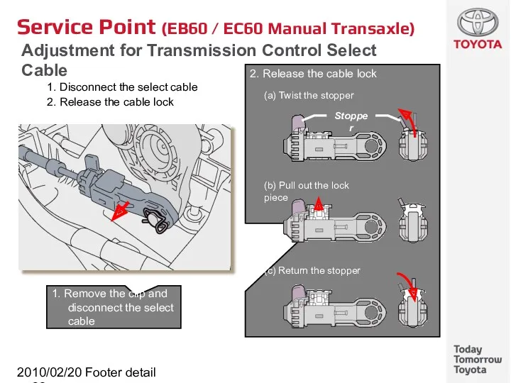
- 20. 10/02/2022 Footer detail Service Point (EB60 / EC60 Manual Transaxle) Adjustment for Transmission Control Select Cable
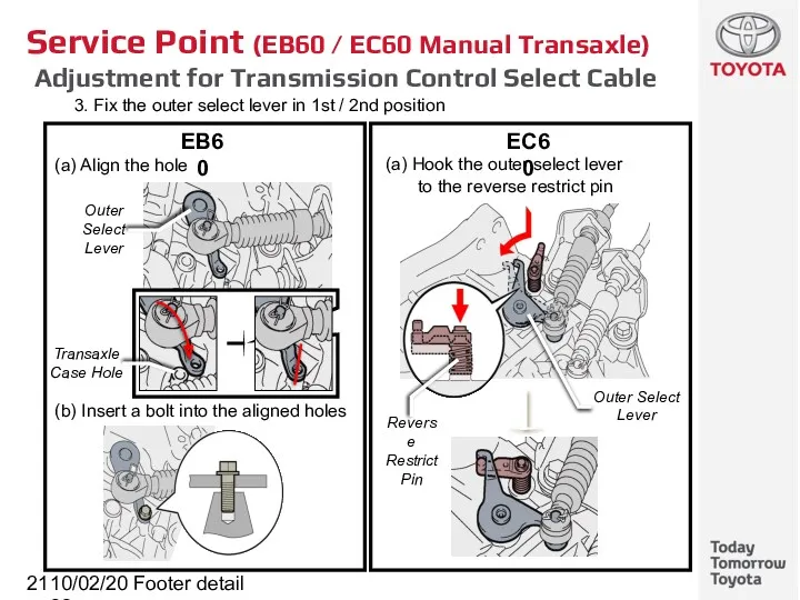
- 21. 10/02/2022 Footer detail Service Point (EB60 / EC60 Manual Transaxle) Adjustment for Transmission Control Select Cable
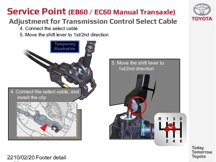
- 22. 10/02/2022 Footer detail Service Point (EB60 / EC60 Manual Transaxle) Adjustment for Transmission Control Select Cable
- 23. 10/02/2022 Footer detail Service Point (EB60 / EC60 Manual Transaxle) Adjustment for Transmission Control Select Cable
- 24. 10/02/2022 Footer detail Gear Shift Indicator System Subtitle
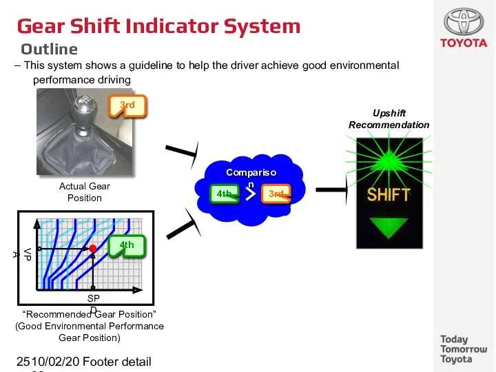
- 25. 10/02/2022 Footer detail Gear Shift Indicator System Outline This system shows a guideline to help the
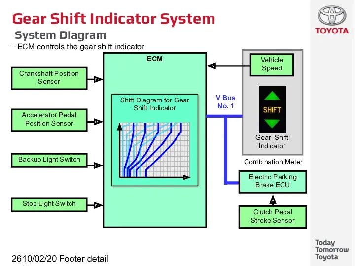
- 26. 10/02/2022 Footer detail Gear Shift Indicator System System Diagram ECM controls the gear shift indicator
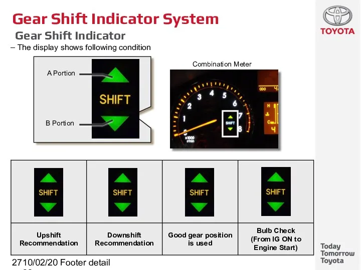
- 27. 10/02/2022 Footer detail Gear Shift Indicator System Gear Shift Indicator The display shows following condition
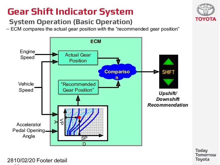
- 28. 10/02/2022 Footer detail Gear Shift Indicator System System Operation (Basic Operation) ECM compares the actual gear
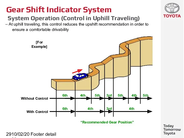
- 29. 10/02/2022 Footer detail Gear Shift Indicator System System Operation (Control in Uphill Traveling) At uphill traveling,
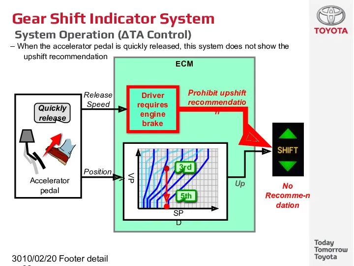
- 30. 10/02/2022 Footer detail Gear Shift Indicator System System Operation (ΔTA Control) When the accelerator pedal is
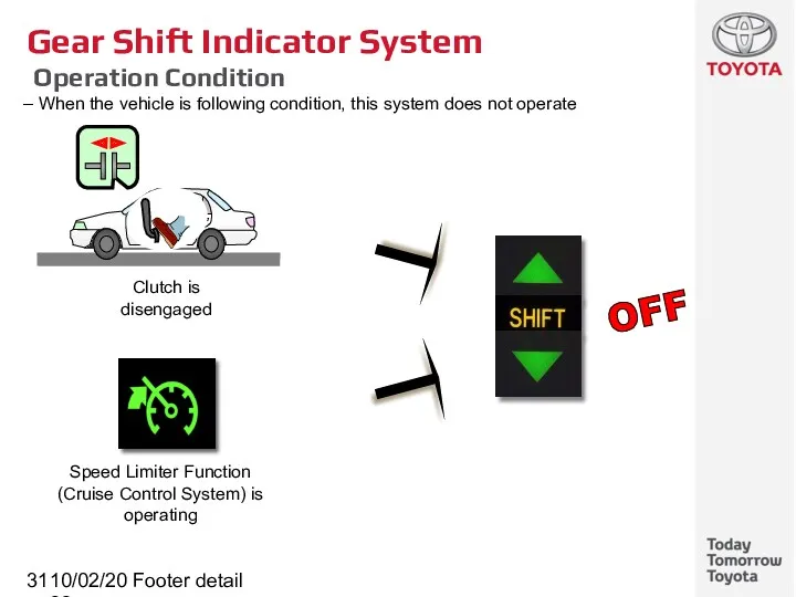
- 31. 10/02/2022 Footer detail Gear Shift Indicator System Operation Condition When the vehicle is following condition, this
- 32. 10/02/2022 Footer detail K111 CVT (Continuously Variable Transaxle) Subtitle
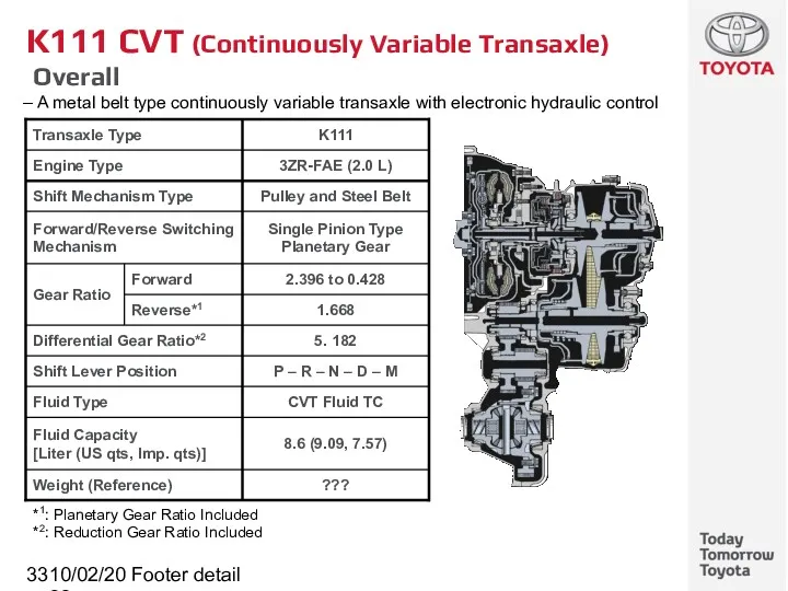
- 33. 10/02/2022 Footer detail K111 CVT (Continuously Variable Transaxle) Overall A metal belt type continuously variable transaxle
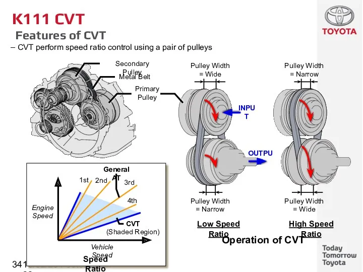
- 34. 10/02/2022 Footer detail K111 CVT Features of CVT CVT perform speed ratio control using a pair
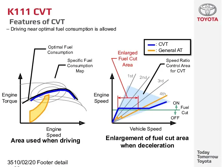
- 35. 10/02/2022 Footer detail K111 CVT Features of CVT Driving near optimal fuel consumption is allowed
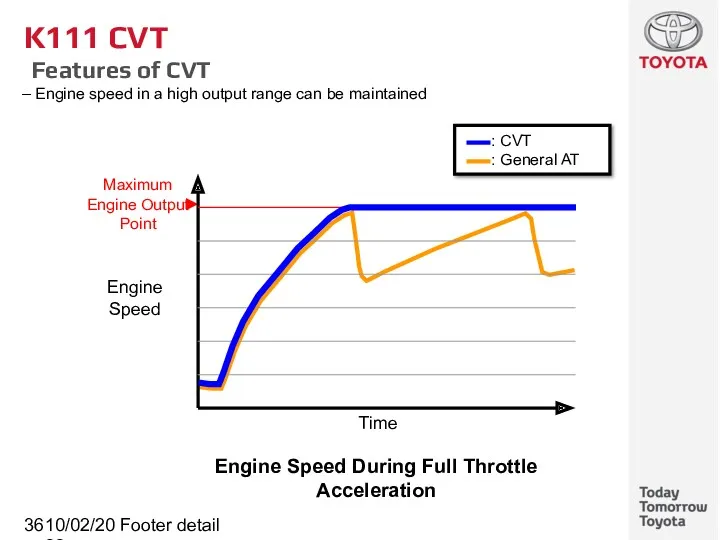
- 36. 10/02/2022 Footer detail K111 CVT Features of CVT Engine speed in a high output range can
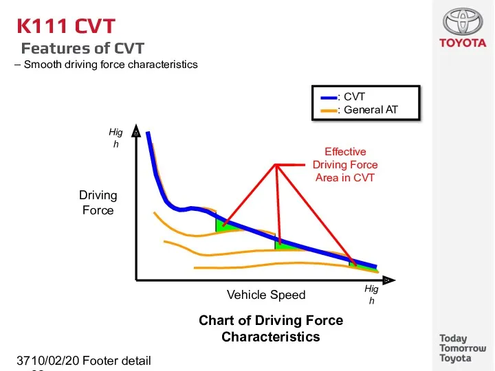
- 37. 10/02/2022 Footer detail K111 CVT Features of CVT Smooth driving force characteristics Driving Force High Vehicle
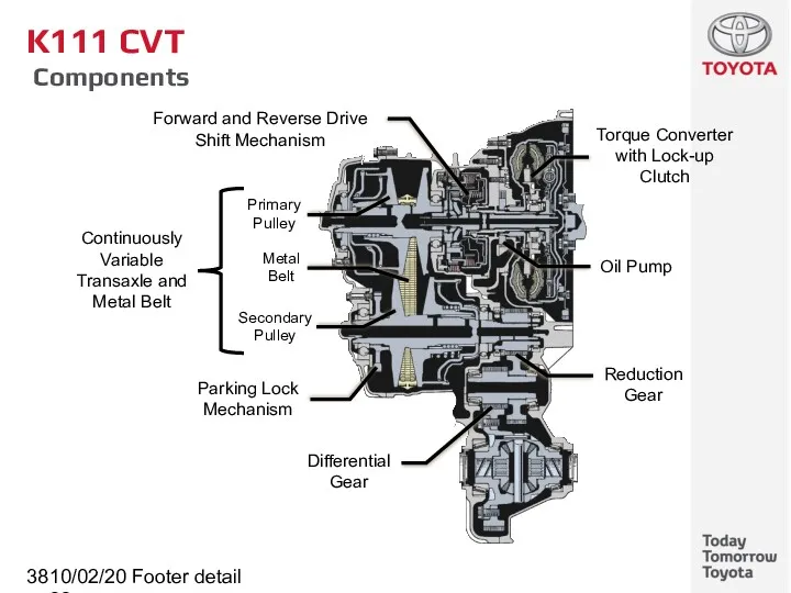
- 38. 10/02/2022 Footer detail K111 CVT Components Torque Converter with Lock-up Clutch Continuously Variable Transaxle and Metal
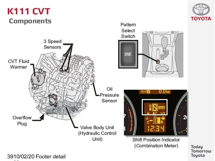
- 39. 10/02/2022 Footer detail K111 CVT Components
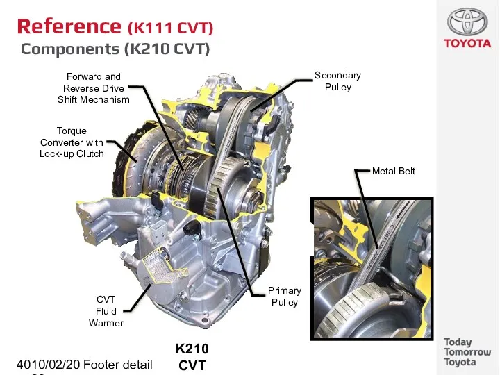
- 40. 10/02/2022 Footer detail Reference (K111 CVT) Components (K210 CVT)
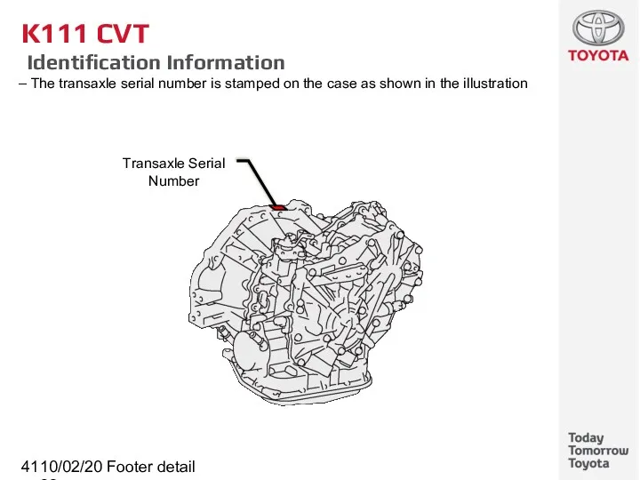
- 41. 10/02/2022 Footer detail K111 CVT Identification Information The transaxle serial number is stamped on the case
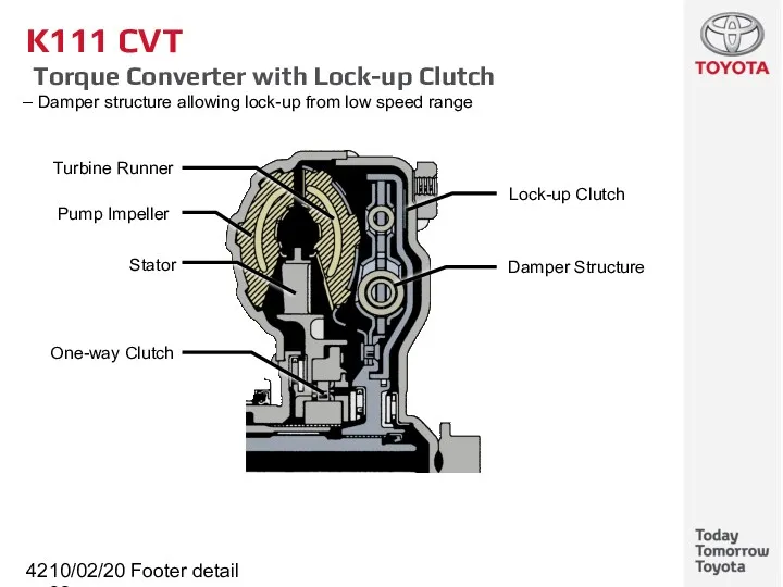
- 42. 10/02/2022 Footer detail K111 CVT Torque Converter with Lock-up Clutch Damper structure allowing lock-up from low
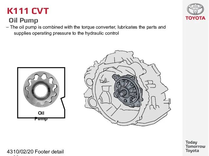
- 43. 10/02/2022 Footer detail K111 CVT Oil Pump The oil pump is combined with the torque converter,
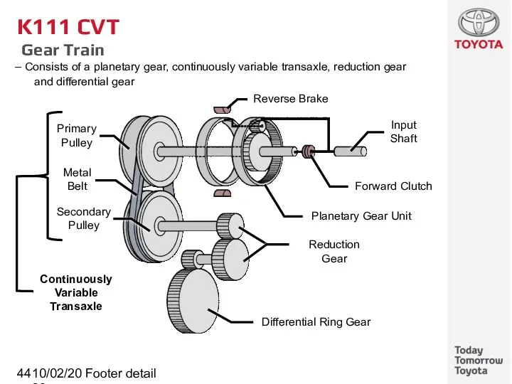
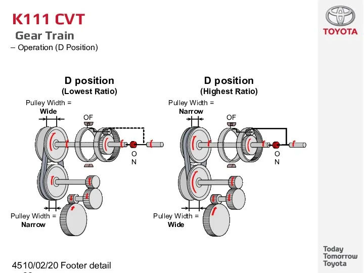
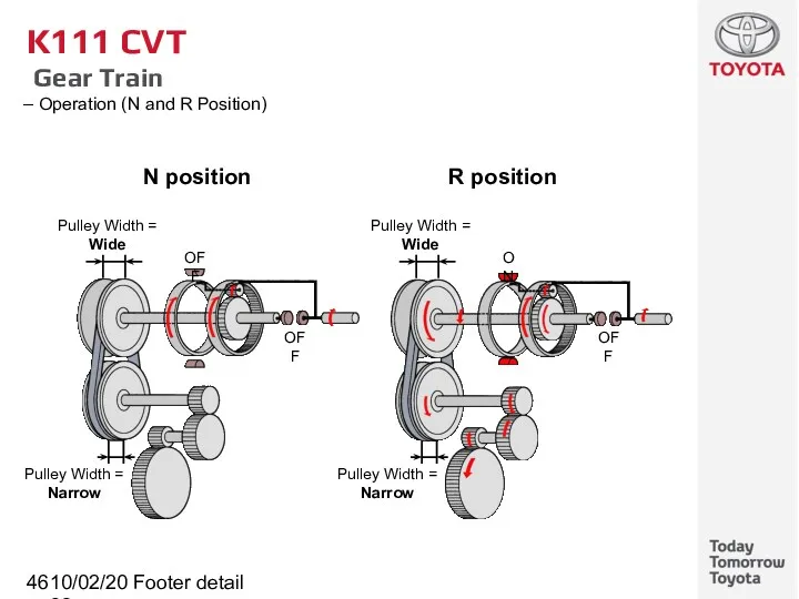
- 44. 10/02/2022 Footer detail K111 CVT Gear Train Consists of a planetary gear, continuously variable transaxle, reduction
- 45. 10/02/2022 Footer detail K111 CVT Gear Train Operation (D Position)
- 46. 10/02/2022 Footer detail K111 CVT Gear Train Operation (N and R Position)
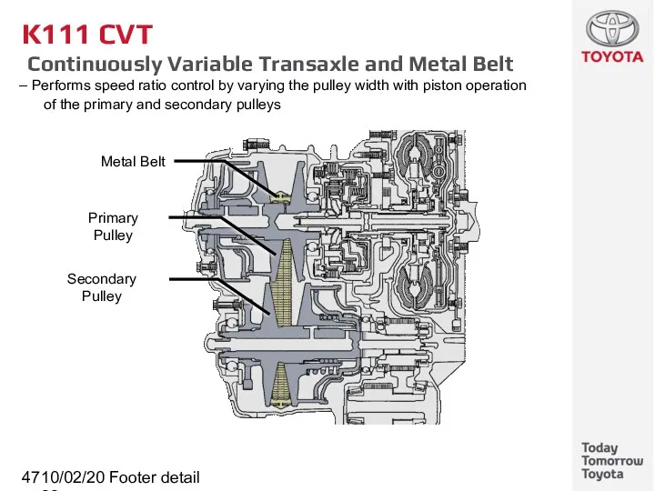
- 47. 10/02/2022 Footer detail K111 CVT Continuously Variable Transaxle and Metal Belt Performs speed ratio control by
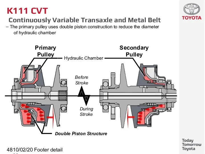
- 48. 10/02/2022 Footer detail K111 CVT Continuously Variable Transaxle and Metal Belt The primary pulley uses double
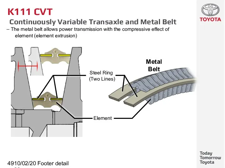
- 49. 10/02/2022 Footer detail K111 CVT Continuously Variable Transaxle and Metal Belt The metal belt allows power
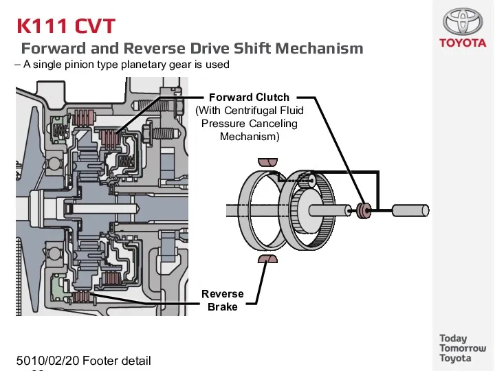
- 50. 10/02/2022 Footer detail K111 CVT Forward and Reverse Drive Shift Mechanism A single pinion type planetary
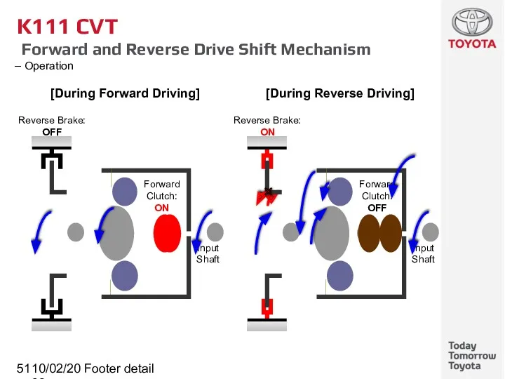
- 51. 10/02/2022 Footer detail K111 CVT Forward and Reverse Drive Shift Mechanism Operation
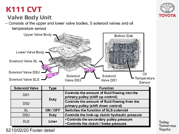
- 52. 10/02/2022 Footer detail K111 CVT Valve Body Unit Consists of the upper and lower valve bodies,
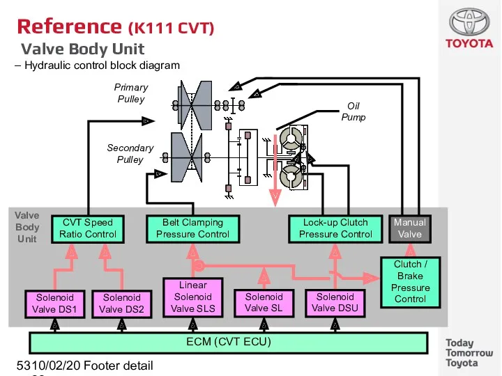
- 53. 10/02/2022 Footer detail Reference (K111 CVT) Valve Body Unit Hydraulic control block diagram Primary Pulley Secondary
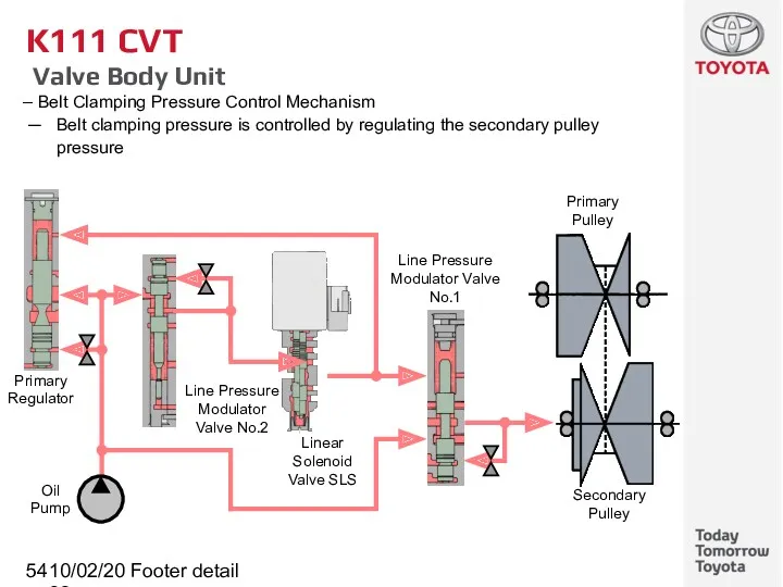
- 54. 10/02/2022 Footer detail K111 CVT Valve Body Unit Belt Clamping Pressure Control Mechanism Belt clamping pressure
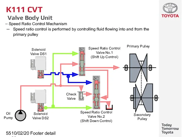
- 55. 10/02/2022 Footer detail K111 CVT Valve Body Unit Speed Ratio Control Mechanism Speed ratio control is
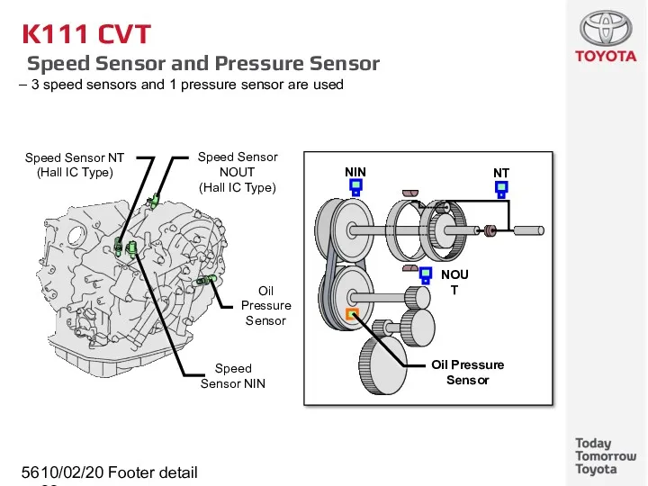
- 56. 10/02/2022 Footer detail K111 CVT Speed Sensor and Pressure Sensor 3 speed sensors and 1 pressure
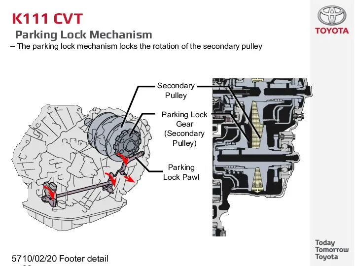
- 57. 10/02/2022 Footer detail K111 CVT Parking Lock Mechanism The parking lock mechanism locks the rotation of
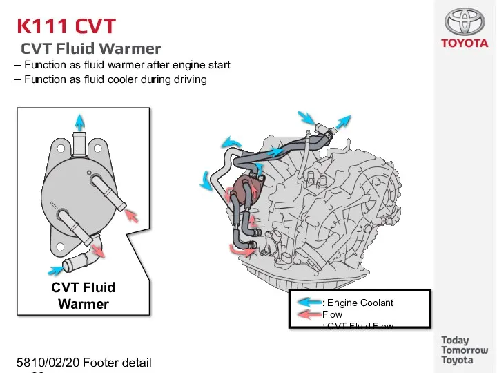
- 58. 10/02/2022 Footer detail K111 CVT CVT Fluid Warmer Function as fluid warmer after engine start Function
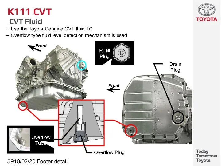
- 59. 10/02/2022 Footer detail K111 CVT CVT Fluid Use the Toyota Genuine CVT fluid TC Overflow type
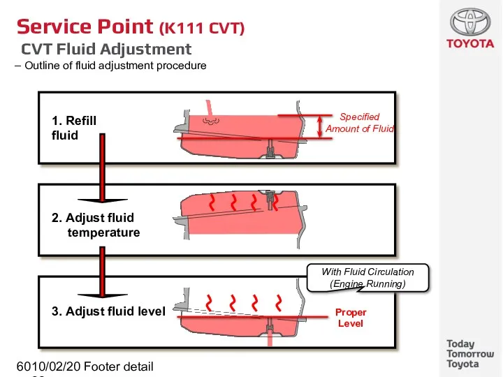
- 60. 10/02/2022 Footer detail Service Point (K111 CVT) CVT Fluid Adjustment Outline of fluid adjustment procedure 1.
- 61. 10/02/2022 Footer detail Service Point (K111 CVT) CVT Fluid Adjustment Procedure 1. Refill fluid
- 62. 10/02/2022 Footer detail Service Point (K111 CVT) CVT Fluid Adjustment Procedure 2. Adjust fluid temperature
- 63. 10/02/2022 Footer detail Service Point (K111 CVT) CVT Fluid Adjustment Procedure 3. Adjust fluid level
- 64. 10/02/2022 Footer detail K111 CVT Shift Lever Cable length adjustment mechanism Electrical type shift lock system
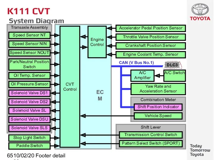
- 65. 10/02/2022 Footer detail K111 CVT System Diagram
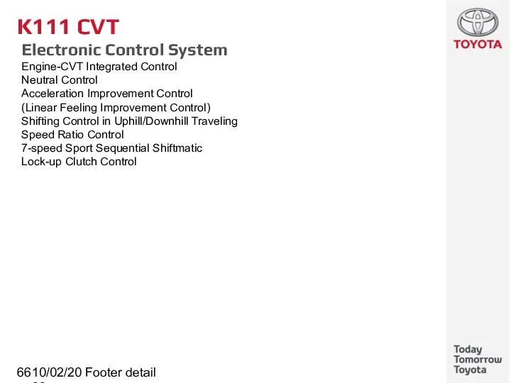
- 66. 10/02/2022 Footer detail K111 CVT Electronic Control System Engine-CVT Integrated Control Neutral Control Acceleration Improvement Control
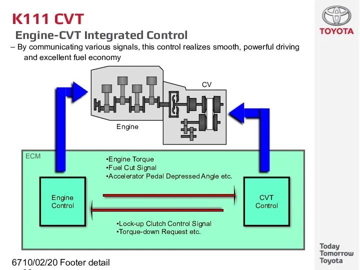
- 67. 10/02/2022 Footer detail ECM K111 CVT Engine-CVT Integrated Control By communicating various signals, this control realizes
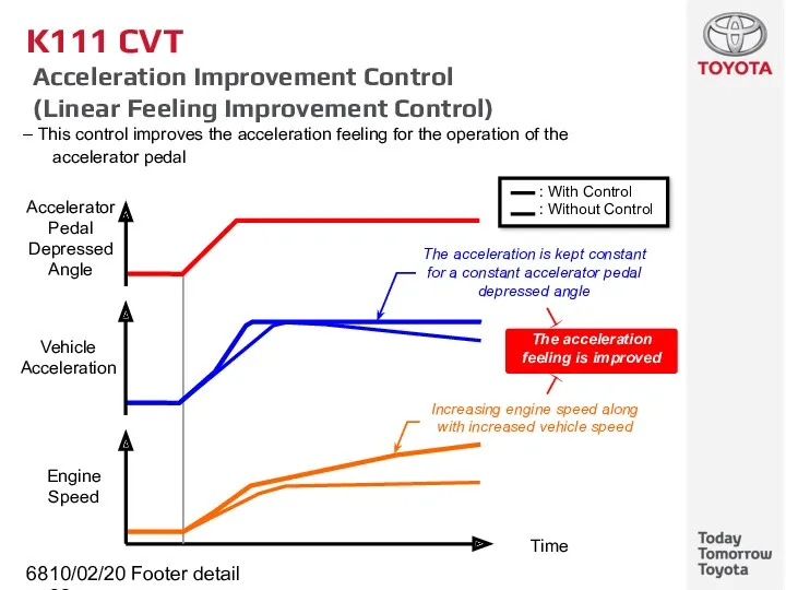
- 68. 10/02/2022 Footer detail K111 CVT Acceleration Improvement Control (Linear Feeling Improvement Control) This control improves the
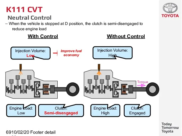
- 69. 10/02/2022 Footer detail K111 CVT Neutral Control When the vehicle is stopped at D position, the
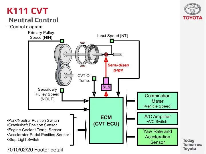
- 70. 10/02/2022 Footer detail K111 CVT Neutral Control Control diagram
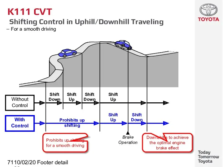
- 71. 10/02/2022 Footer detail K111 CVT Shifting Control in Uphill/Downhill Traveling For a smooth driving
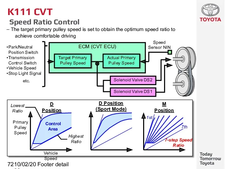
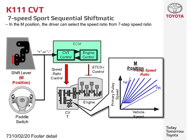
- 72. 10/02/2022 Footer detail K111 CVT Speed Ratio Control The target primary pulley speed is set to
- 73. 10/02/2022 Footer detail K111 CVT 7-speed Sport Sequential Shiftmatic In the M position, the driver can
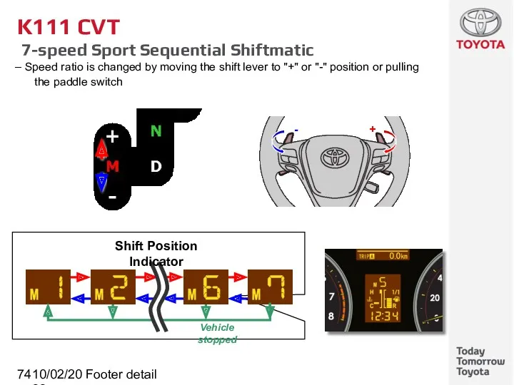
- 74. 10/02/2022 Footer detail K111 CVT 7-speed Sport Sequential Shiftmatic Speed ratio is changed by moving the
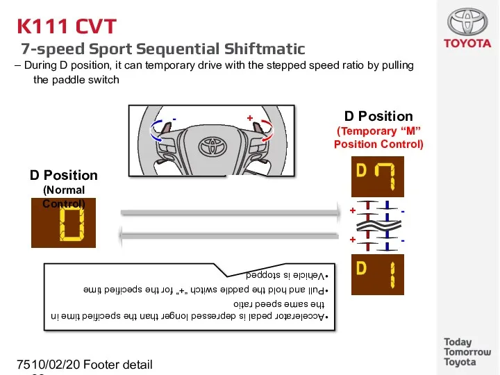
- 75. 10/02/2022 Footer detail K111 CVT 7-speed Sport Sequential Shiftmatic During D position, it can temporary drive
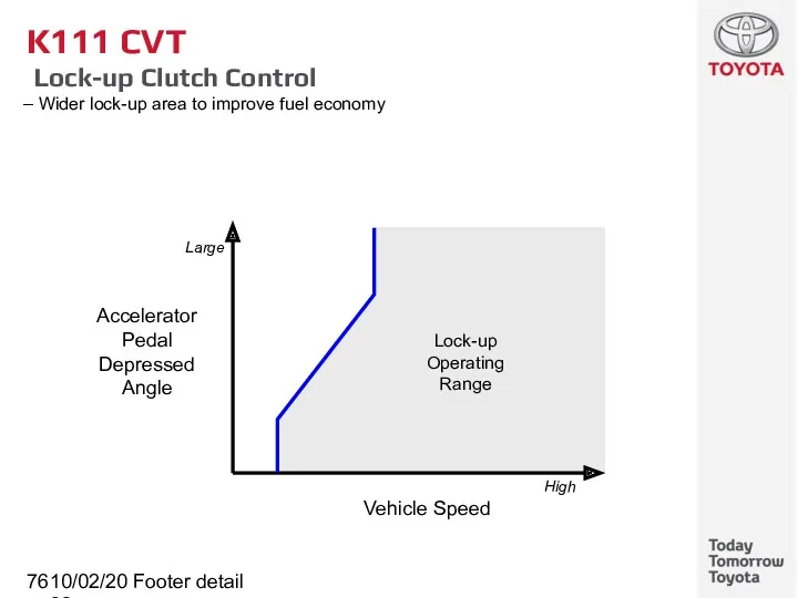
- 76. 10/02/2022 Footer detail K111 CVT Lock-up Clutch Control Wider lock-up area to improve fuel economy Accelerator
- 77. 10/02/2022 Footer detail K111 CVT Fail-safe [1/2] This function minimizes the loss of operation when any
- 78. 10/02/2022 Footer detail K111 CVT Fail-safe [2/2] This function minimizes the loss of operation when any
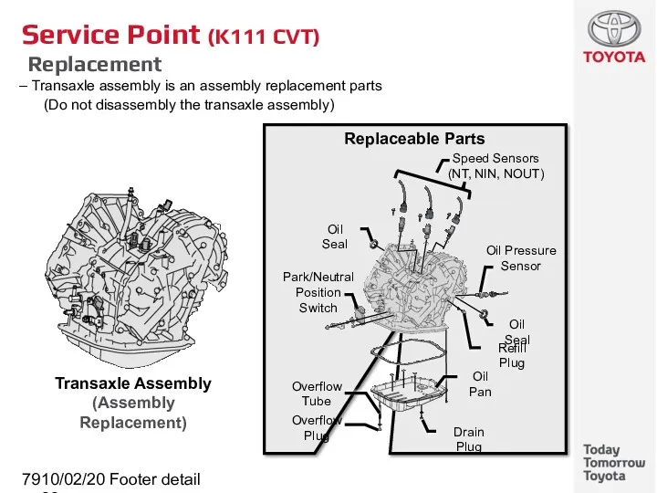
- 79. 10/02/2022 Footer detail Service Point (K111 CVT) Replacement Transaxle assembly is an assembly replacement parts (Do
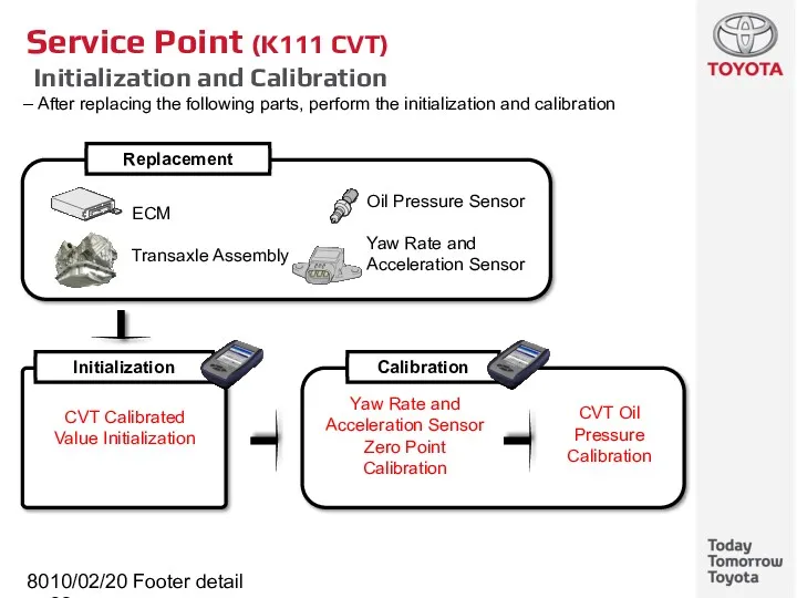
- 80. 10/02/2022 Footer detail Service Point (K111 CVT) Initialization and Calibration After replacing the following parts, perform
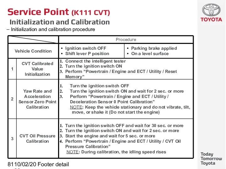
- 81. 10/02/2022 Footer detail Service Point (K111 CVT) Initialization and Calibration Initialization and calibration procedure
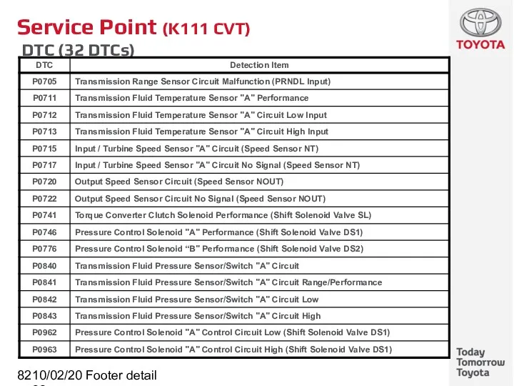
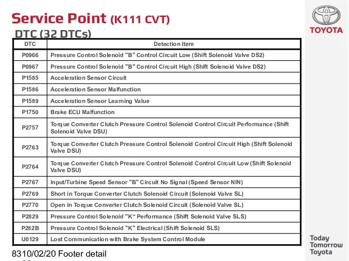
- 82. 10/02/2022 Footer detail Service Point (K111 CVT) DTC (32 DTCs)
- 83. 10/02/2022 Footer detail Service Point (K111 CVT) DTC (32 DTCs)
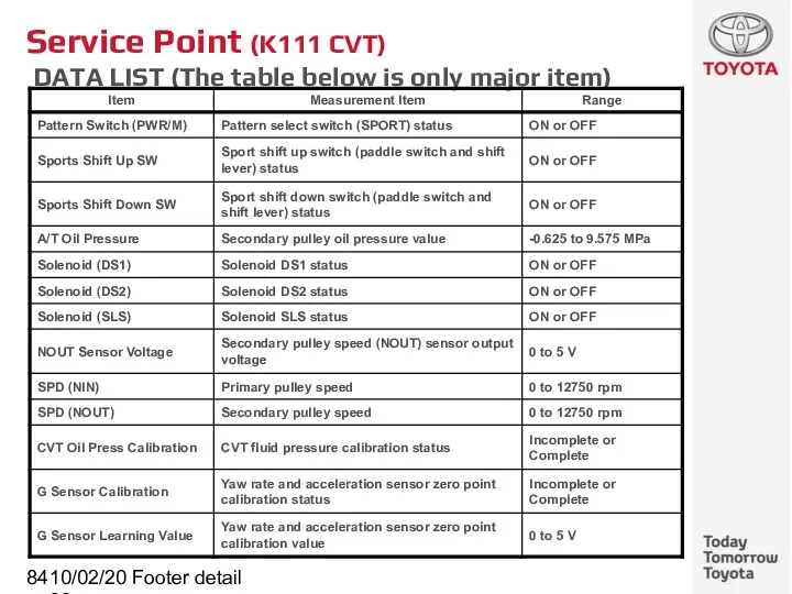
- 84. 10/02/2022 Footer detail Service Point (K111 CVT) DATA LIST (The table below is only major item)
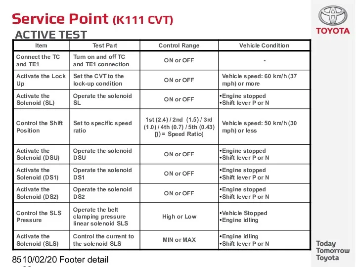
- 85. 10/02/2022 Footer detail Service Point (K111 CVT) ACTIVE TEST
- 86. 10/02/2022 Footer detail K311 CVT (Continuously Variable Transaxle) Subtitle
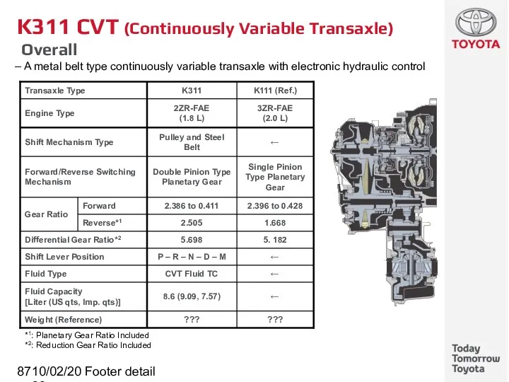
- 87. 10/02/2022 Footer detail K311 CVT (Continuously Variable Transaxle) Overall A metal belt type continuously variable transaxle
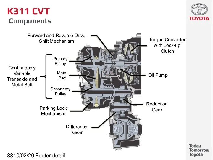
- 88. 10/02/2022 Footer detail K311 CVT Components Torque Converter with Lock-up Clutch Continuously Variable Transaxle and Metal
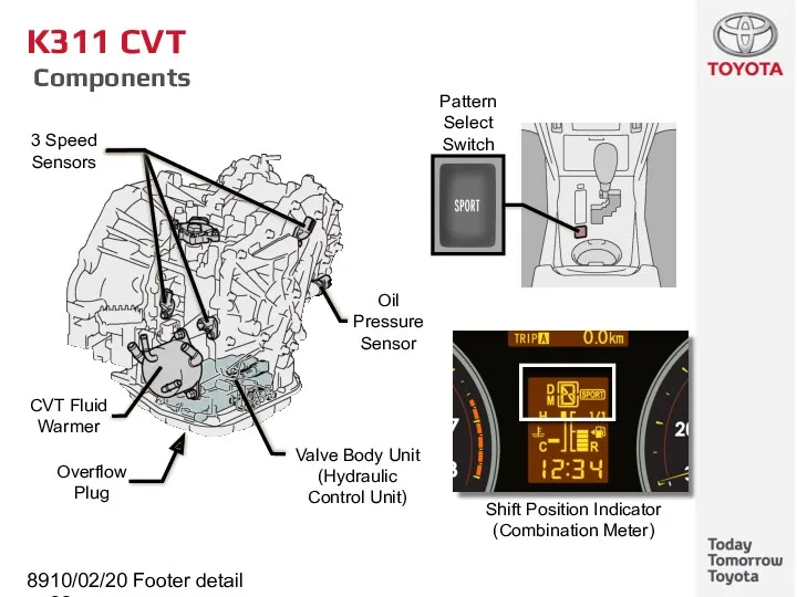
- 89. 10/02/2022 Footer detail K311 CVT Components
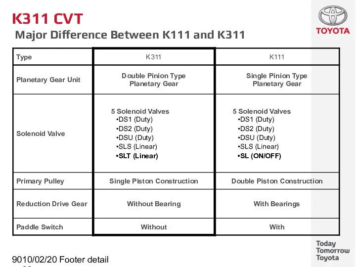
- 90. 10/02/2022 Footer detail K311 CVT Major Difference Between K111 and K311
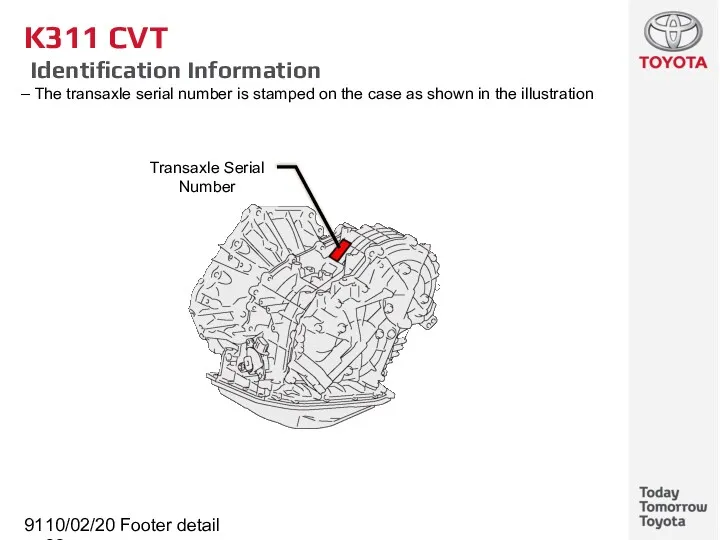
- 91. 10/02/2022 Footer detail K311 CVT Identification Information The transaxle serial number is stamped on the case
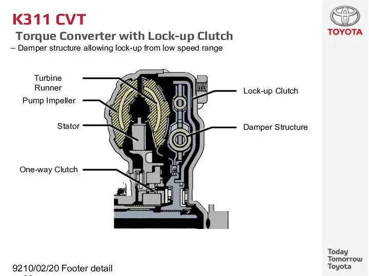
- 92. 10/02/2022 Footer detail K311 CVT Torque Converter with Lock-up Clutch Damper structure allowing lock-up from low
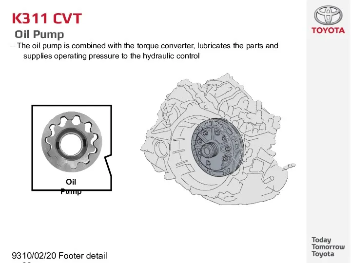
- 93. 10/02/2022 Footer detail K311 CVT Oil Pump The oil pump is combined with the torque converter,
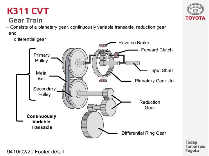
- 94. 10/02/2022 Footer detail K311 CVT Gear Train Consists of a planetary gear, continuously variable transaxle, reduction
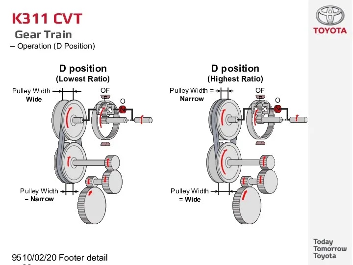
- 95. 10/02/2022 Footer detail K311 CVT Gear Train Operation (D Position)
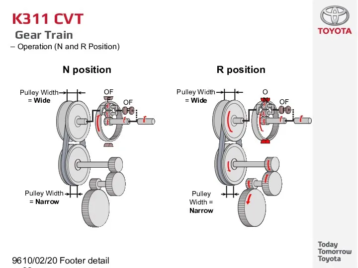
- 96. 10/02/2022 Footer detail K311 CVT Gear Train Operation (N and R Position) N position R position
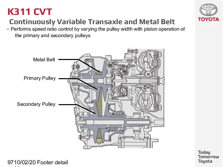
- 97. 10/02/2022 Footer detail K311 CVT Continuously Variable Transaxle and Metal Belt Performs speed ratio control by
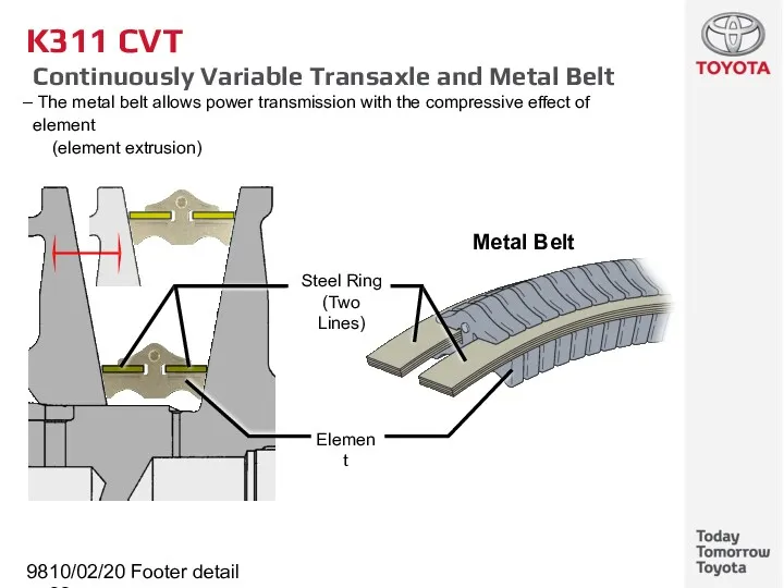
- 98. 10/02/2022 Footer detail K311 CVT Continuously Variable Transaxle and Metal Belt The metal belt allows power
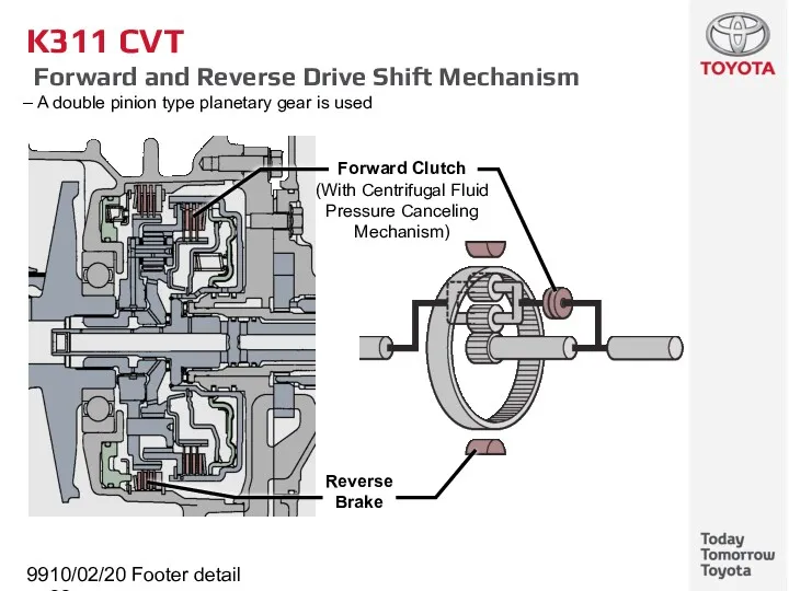
- 99. 10/02/2022 Footer detail K311 CVT Forward and Reverse Drive Shift Mechanism A double pinion type planetary
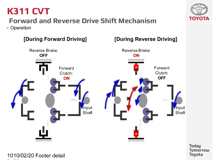
- 100. 10/02/2022 Footer detail K311 CVT Forward and Reverse Drive Shift Mechanism Operation
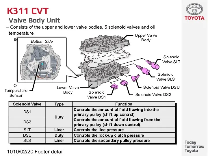
- 101. 10/02/2022 Footer detail K311 CVT Valve Body Unit Consists of the upper and lower valve bodies,
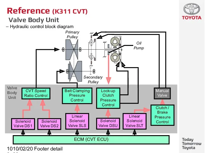
- 102. 10/02/2022 Footer detail Reference (K311 CVT) Valve Body Unit Hydraulic control block diagram Secondary Pulley Primary
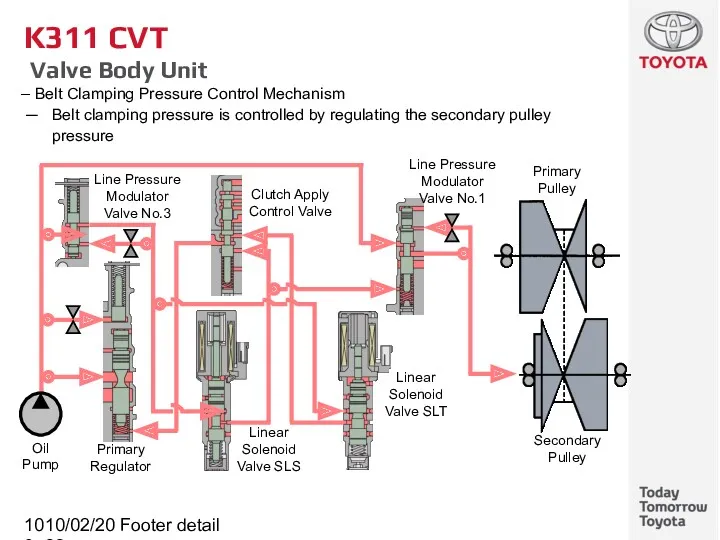
- 103. 10/02/2022 Footer detail K311 CVT Valve Body Unit Belt Clamping Pressure Control Mechanism Belt clamping pressure
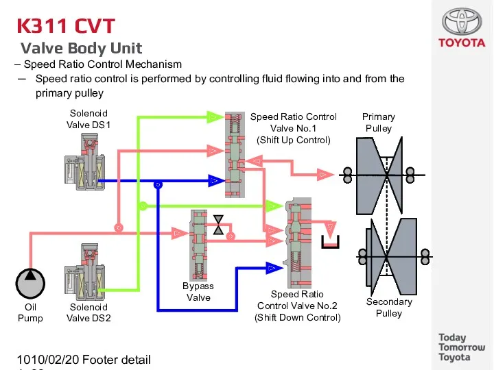
- 104. 10/02/2022 Footer detail K311 CVT Valve Body Unit Speed Ratio Control Mechanism Speed ratio control is
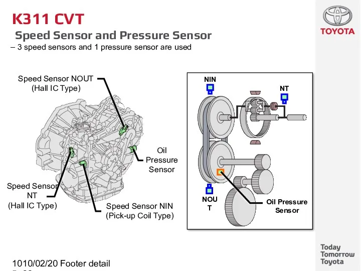
- 105. 10/02/2022 Footer detail K311 CVT Speed Sensor and Pressure Sensor 3 speed sensors and 1 pressure
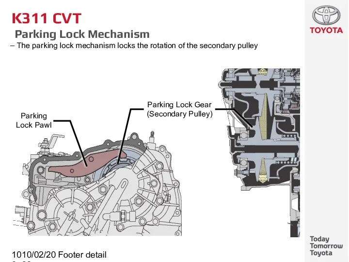
- 106. 10/02/2022 Footer detail K311 CVT Parking Lock Mechanism The parking lock mechanism locks the rotation of
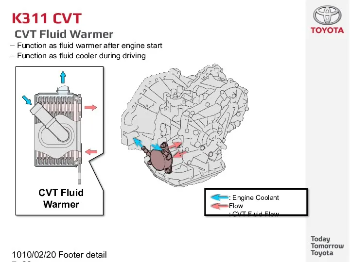
- 107. 10/02/2022 Footer detail CVT Fluid Warmer K311 CVT CVT Fluid Warmer Function as fluid warmer after
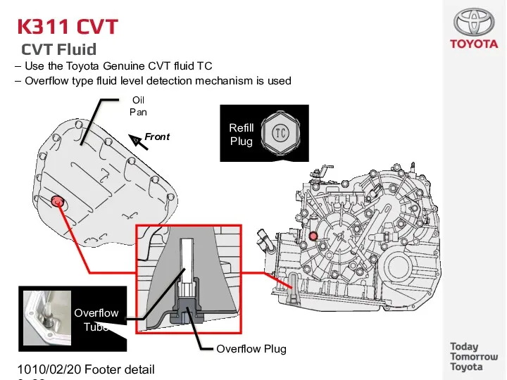
- 108. 10/02/2022 Footer detail K311 CVT CVT Fluid Use the Toyota Genuine CVT fluid TC Overflow type
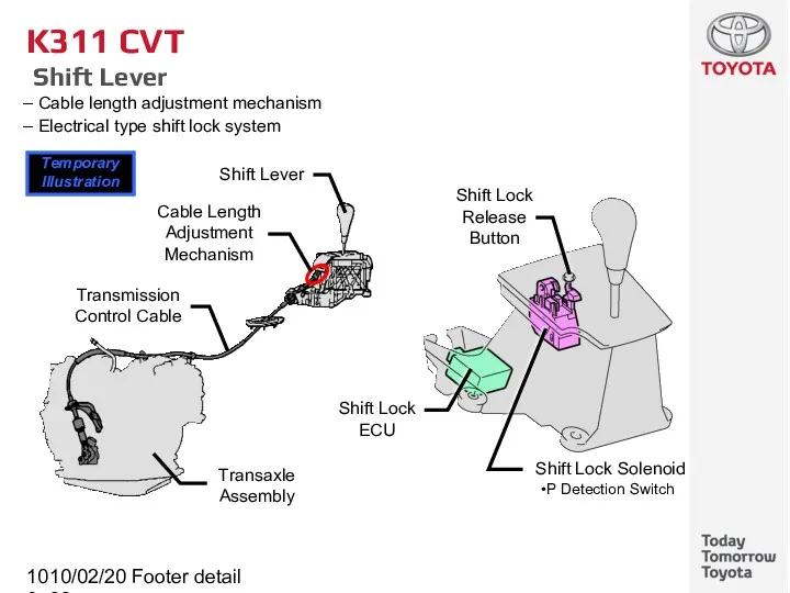
- 109. 10/02/2022 Footer detail K311 CVT Shift Lever Cable length adjustment mechanism Electrical type shift lock system
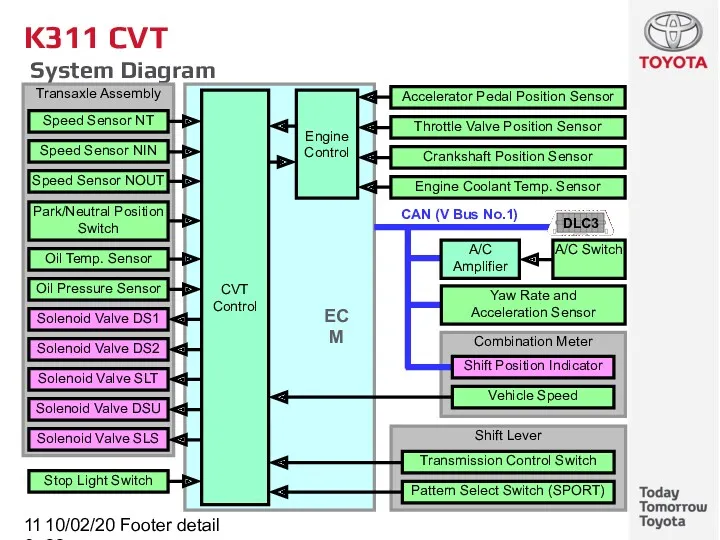
- 110. 10/02/2022 Footer detail K311 CVT System Diagram
- 111. 10/02/2022 Footer detail K311 CVT Electronic Control System These controls are basically the same as K111
- 112. 10/02/2022 Footer detail K311 CVT Fail-safe [1/2] This function minimizes the loss of operation when any
- 113. 10/02/2022 Footer detail K311 CVT Fail-safe [2/2] This function minimizes the loss of operation when any
- 114. 10/02/2022 Footer detail Service Point (K311 CVT) Replacement Transaxle assembly is an assembly replacement parts (Do
- 115. 10/02/2022 Footer detail Service Point (K311 CVT) Initialization and Calibration After replacing the following parts, perform
- 116. 10/02/2022 Footer detail Brake Subtitle
- 117. 10/02/2022 Footer detail Brake Rear Brake Use the socket wrench (13 mm) to remove or install
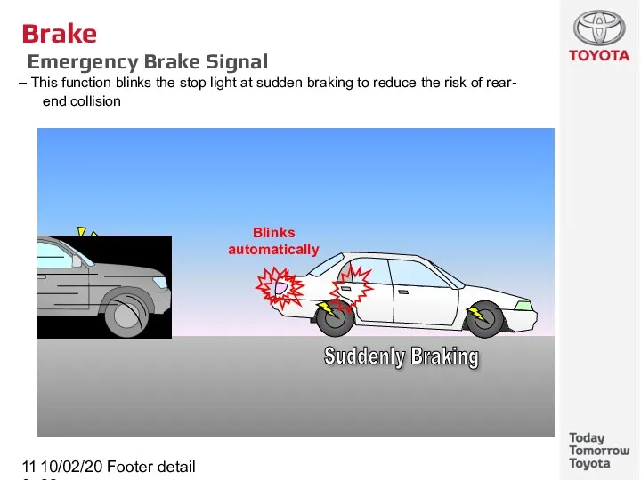
- 118. 10/02/2022 Footer detail Brake Emergency Brake Signal This function blinks the stop light at sudden braking
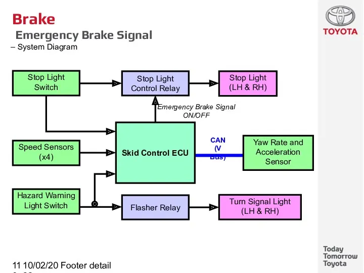
- 119. 10/02/2022 Footer detail Brake Emergency Brake Signal System Diagram Speed Sensors (x4) Turn Signal Light (LH
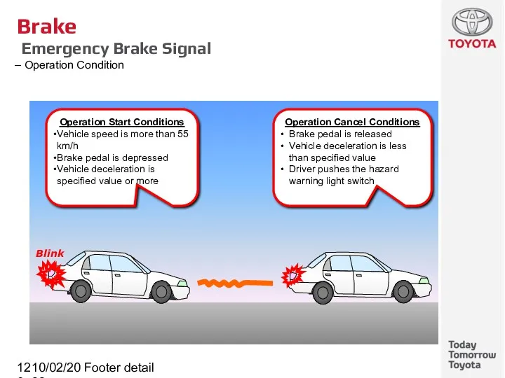
- 120. 10/02/2022 Footer detail Brake Emergency Brake Signal Operation Condition Operation Start Conditions Vehicle speed is more
- 121. 10/02/2022 Footer detail Brake Control System Subtitle
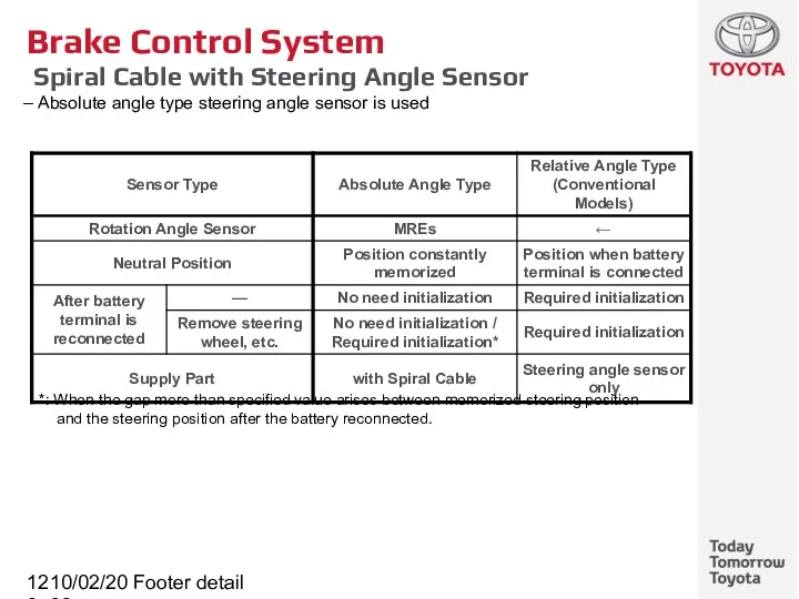
- 122. 10/02/2022 Footer detail Brake Control System Spiral Cable with Steering Angle Sensor Absolute angle type steering
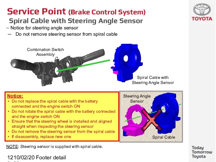
- 123. 10/02/2022 Footer detail Service Point (Brake Control System) Spiral Cable with Steering Angle Sensor Notice for
- 124. 10/02/2022 Footer detail Electric Parking Brake Subtitle
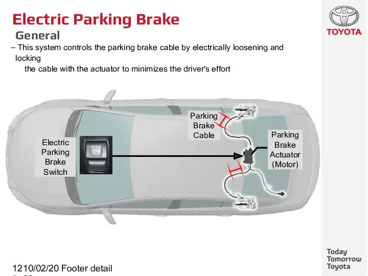
- 125. 10/02/2022 Footer detail Electric Parking Brake General This system controls the parking brake cable by electrically
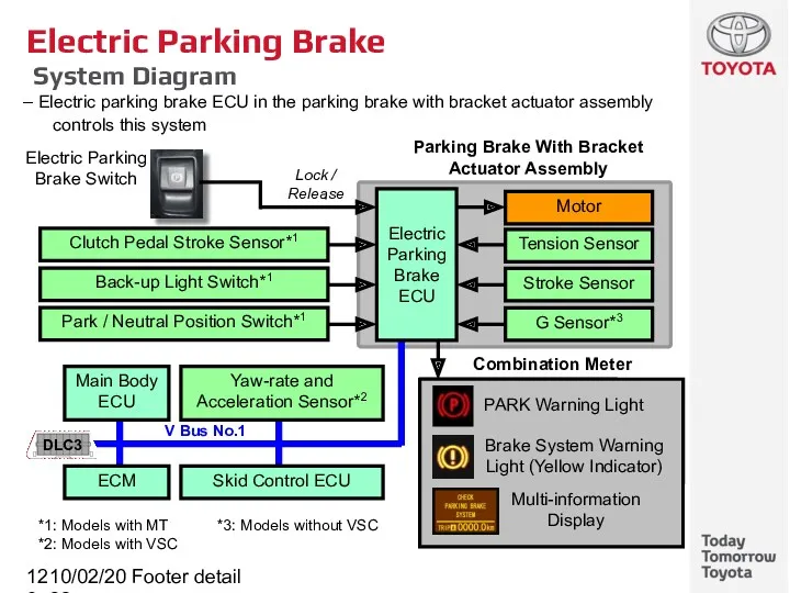
- 126. 10/02/2022 Footer detail Electric Parking Brake System Diagram Electric parking brake ECU in the parking brake
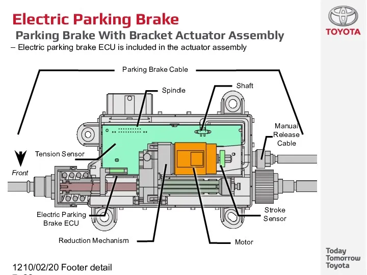
- 127. 10/02/2022 Footer detail Electric Parking Brake Parking Brake With Bracket Actuator Assembly Electric parking brake ECU
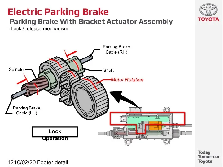
- 128. 10/02/2022 Footer detail Electric Parking Brake Parking Brake With Bracket Actuator Assembly Lock / release mechanism
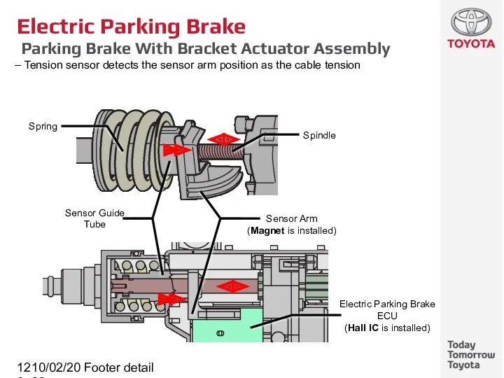
- 129. 10/02/2022 Footer detail Electric Parking Brake Parking Brake With Bracket Actuator Assembly Tension sensor detects the
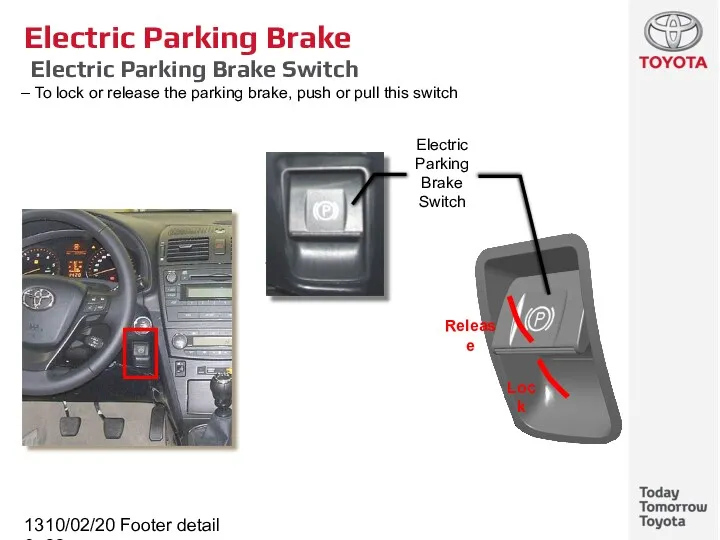
- 130. 10/02/2022 Footer detail Electric Parking Brake Electric Parking Brake Switch To lock or release the parking
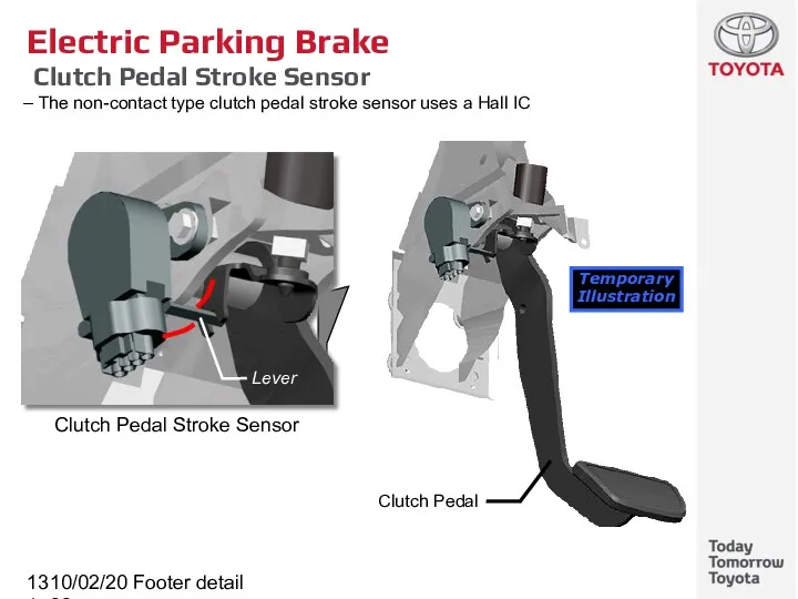
- 131. 10/02/2022 Footer detail Electric Parking Brake Clutch Pedal Stroke Sensor The non-contact type clutch pedal stroke
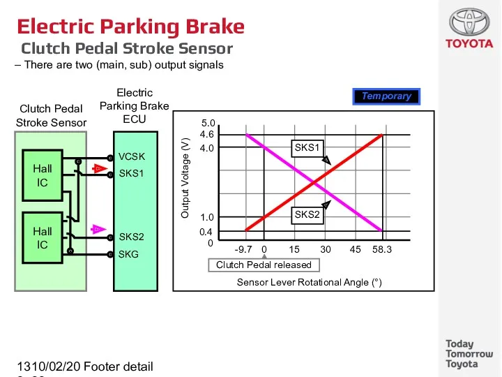
- 132. 10/02/2022 Footer detail Electric Parking Brake Clutch Pedal Stroke Sensor There are two (main, sub) output
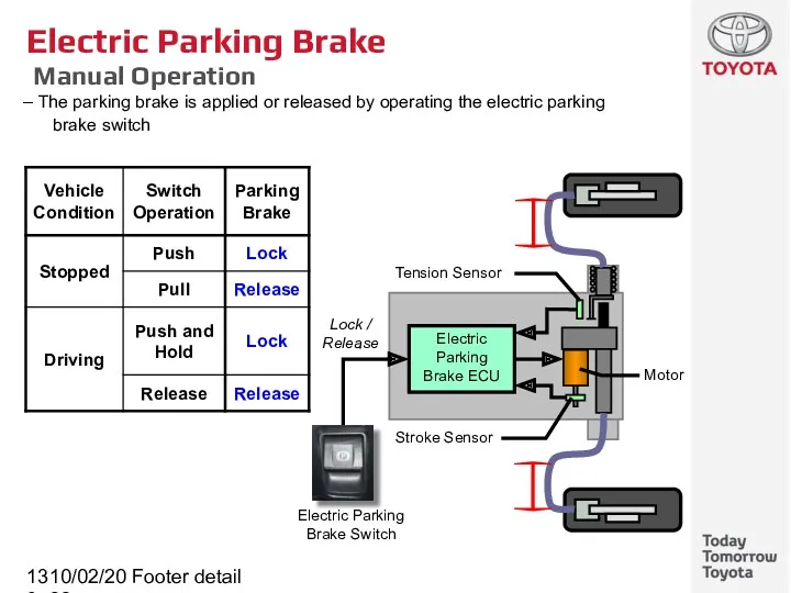
- 133. 10/02/2022 Footer detail Electric Parking Brake Manual Operation The parking brake is applied or released by
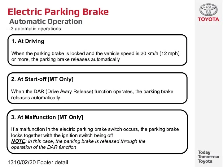
- 134. 10/02/2022 Footer detail Electric Parking Brake Automatic Operation 3 automatic operations 1. At Driving When the
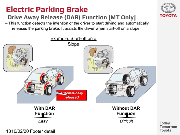
- 135. 10/02/2022 Footer detail Electric Parking Brake Drive Away Release (DAR) Function [MT Only] This function detects
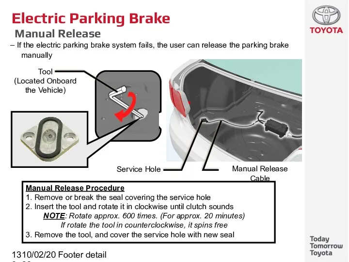
- 136. 10/02/2022 Footer detail Electric Parking Brake Manual Release If the electric parking brake system fails, the
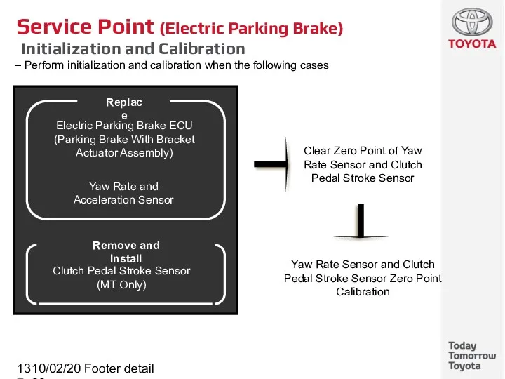
- 137. 10/02/2022 Footer detail Service Point (Electric Parking Brake) Initialization and Calibration Perform initialization and calibration when
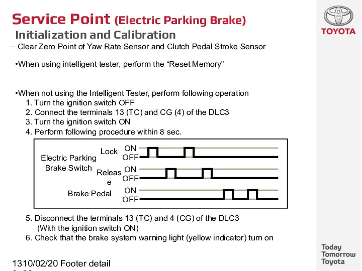
- 138. 10/02/2022 Footer detail Service Point (Electric Parking Brake) Initialization and Calibration Clear Zero Point of Yaw
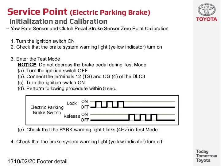
- 139. 10/02/2022 Footer detail Service Point (Electric Parking Brake) Initialization and Calibration Yaw Rate Sensor and Clutch
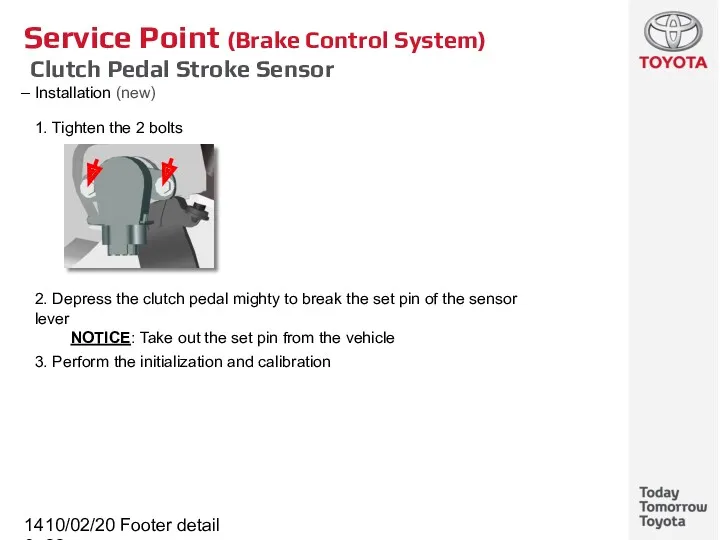
- 140. 10/02/2022 Footer detail Service Point (Brake Control System) Clutch Pedal Stroke Sensor Installation (new) 1. Tighten
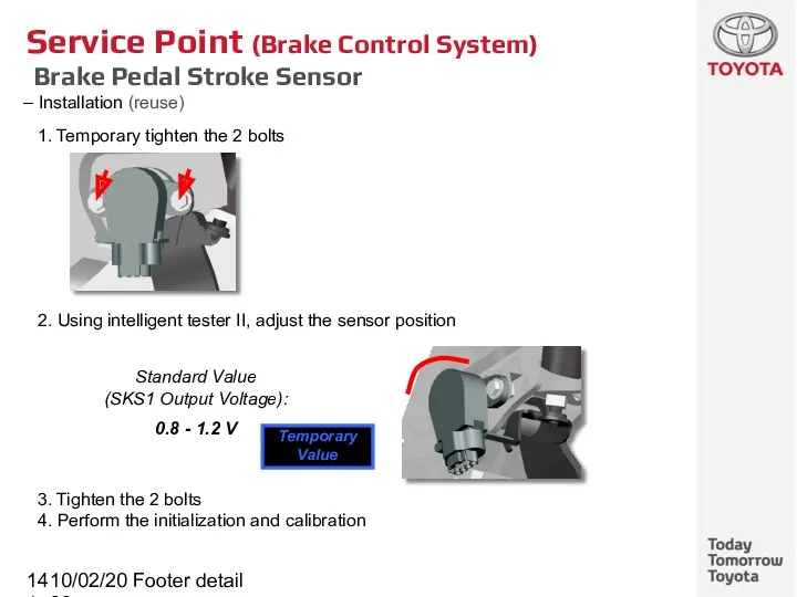
- 141. 10/02/2022 Footer detail Service Point (Brake Control System) Brake Pedal Stroke Sensor Installation (reuse) 1. Temporary
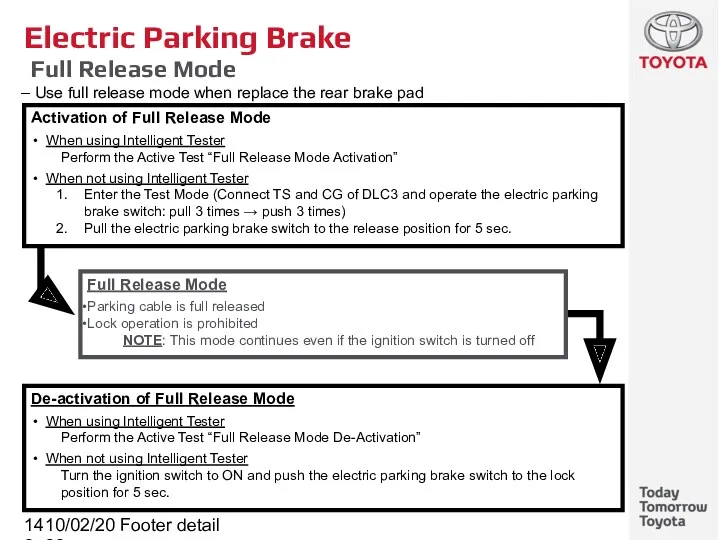
- 142. 10/02/2022 Footer detail Electric Parking Brake Full Release Mode Use full release mode when replace the
- 143. 10/02/2022 Footer detail Electric Parking Brake DTC [1/2]
- 144. 10/02/2022 Footer detail Electric Parking Brake DTC [2/2]
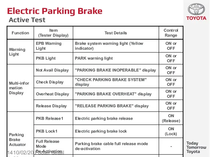
- 145. 10/02/2022 Footer detail Electric Parking Brake Active Test
- 146. 10/02/2022 Footer detail Steering Subtitle
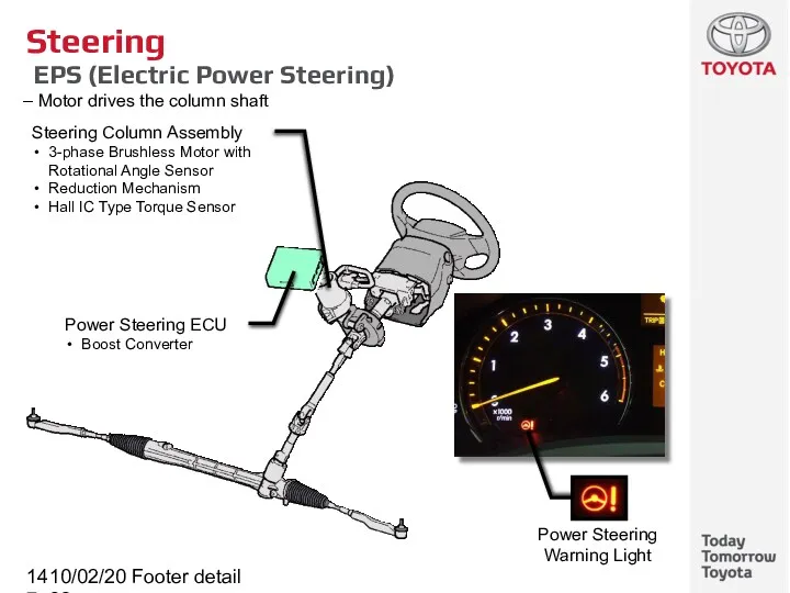
- 147. 10/02/2022 Footer detail Steering Column Assembly 3-phase Brushless Motor with Rotational Angle Sensor Reduction Mechanism Hall
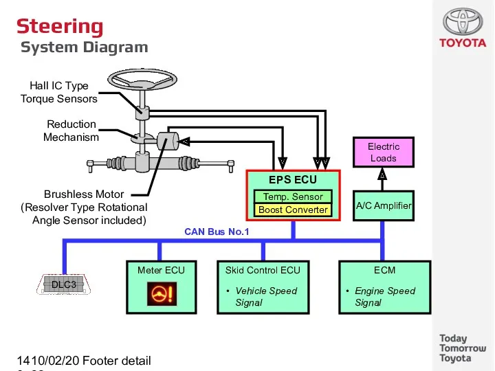
- 148. 10/02/2022 Footer detail Steering System Diagram
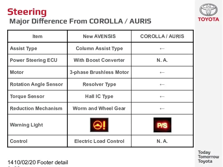
- 149. 10/02/2022 Footer detail Steering Major Difference From COROLLA / AURIS
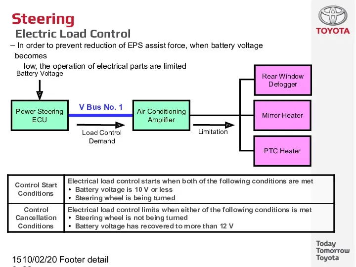
- 150. 10/02/2022 Footer detail Steering Electric Load Control In order to prevent reduction of EPS assist force,
- 152. Скачать презентацию
10/02/2022
Footer detail
Contents
Clutch
EA6# Manual Transaxle
EB60 / EC60 Manual Transaxle
Gear Shift Indicator System
K111
10/02/2022
Footer detail
Contents
Clutch
EA6# Manual Transaxle
EB60 / EC60 Manual Transaxle
Gear Shift Indicator System
K111

10/02/2022
Footer detail
Clutch
Subtitle
10/02/2022
Footer detail
Clutch
Subtitle
10/02/2022
Footer detail
Clutch
CSC (Concentric Sleeve Cylinder) [EB60 and EC60]
CSC has combined
10/02/2022
Footer detail
Clutch
CSC (Concentric Sleeve Cylinder) [EB60 and EC60]
CSC has combined
10/02/2022
Footer detail
Clutch
CSC (Concentric Sleeve Cylinder) [EB60 and EC60]
Construction
The clutch release
10/02/2022
Footer detail
Clutch
CSC (Concentric Sleeve Cylinder) [EB60 and EC60]
Construction
The clutch release
10/02/2022
Footer detail
Service Point (Clutch)
CSC (Concentric Sleeve Cylinder) [EB60 and EC60]
Service
10/02/2022
Footer detail
Service Point (Clutch)
CSC (Concentric Sleeve Cylinder) [EB60 and EC60]
Service
10/02/2022
Footer detail
Service Point (Clutch)
CSC (Concentric Sleeve Cylinder) [EB60 and EC60]
Service
10/02/2022
Footer detail
Service Point (Clutch)
CSC (Concentric Sleeve Cylinder) [EB60 and EC60]
Service
10/02/2022
Footer detail
Service Point (Clutch)
CSC (Concentric Sleeve Cylinder) [EB60 and EC60]
Service
10/02/2022
Footer detail
Service Point (Clutch)
CSC (Concentric Sleeve Cylinder) [EB60 and EC60]
Service
10/02/2022
Footer detail
EA6# Manual Transaxle
Subtitle
10/02/2022
Footer detail
EA6# Manual Transaxle
Subtitle
10/02/2022
Footer detail
EA6# Manual Transaxle
Specifications
*1: For 1st to 4th *2: For 5th, 6th,
10/02/2022
Footer detail
EA6# Manual Transaxle
Specifications
*1: For 1st to 4th *2: For 5th, 6th,
10/02/2022
Footer detail
EB60 / EC60 Manual Transaxle
Subtitle
10/02/2022
Footer detail
EB60 / EC60 Manual Transaxle
Subtitle
10/02/2022
Footer detail
EB60 / EC60 Manual Transaxle
Overall
EB60 / EC60 6-speed manual
10/02/2022
Footer detail
EB60 / EC60 Manual Transaxle
Overall
EB60 / EC60 6-speed manual
10/02/2022
Footer detail
EB60 / EC60 Manual Transaxle
Specifications
*1: 1ZR-FAE *3: For 1st to 4th *5:
10/02/2022
Footer detail
EB60 / EC60 Manual Transaxle
Specifications
*1: 1ZR-FAE *3: For 1st to 4th *5:
10/02/2022
Footer detail
EB60 / EC60 Manual Transaxle
Identification Information
The transaxle serial number
10/02/2022
Footer detail
EB60 / EC60 Manual Transaxle
Identification Information
The transaxle serial number
10/02/2022
Footer detail
EB60 / EC60 Manual Transaxle
Synchromesh Shifting Key
The ball
10/02/2022
Footer detail
EB60 / EC60 Manual Transaxle
Synchromesh Shifting Key
The ball
10/02/2022
Footer detail
EB60 / EC60 Manual Transaxle
Oil Separator
The oil separator prevents
10/02/2022
Footer detail
EB60 / EC60 Manual Transaxle
Oil Separator
The oil separator prevents
10/02/2022
Footer detail
EB60 / EC60 Manual Transaxle
Pre-synchronizing System
While reverse is selected,
10/02/2022
Footer detail
EB60 / EC60 Manual Transaxle
Pre-synchronizing System
While reverse is selected,
10/02/2022
Footer detail
EB60 / EC60 Manual Transaxle
Transmission Control Select Cable
Select cable
10/02/2022
Footer detail
EB60 / EC60 Manual Transaxle
Transmission Control Select Cable
Select cable
10/02/2022
Footer detail
Service Point (EB60 / EC60 Manual Transaxle)
Adjustment for Transmission Control
10/02/2022
Footer detail
Service Point (EB60 / EC60 Manual Transaxle)
Adjustment for Transmission Control
10/02/2022
Footer detail
Service Point (EB60 / EC60 Manual Transaxle)
Adjustment for Transmission Control
10/02/2022
Footer detail
Service Point (EB60 / EC60 Manual Transaxle)
Adjustment for Transmission Control
10/02/2022
Footer detail
Service Point (EB60 / EC60 Manual Transaxle)
Adjustment for Transmission Control
10/02/2022
Footer detail
Service Point (EB60 / EC60 Manual Transaxle)
Adjustment for Transmission Control
10/02/2022
Footer detail
Service Point (EB60 / EC60 Manual Transaxle)
Adjustment for Transmission Control
10/02/2022
Footer detail
Service Point (EB60 / EC60 Manual Transaxle)
Adjustment for Transmission Control
10/02/2022
Footer detail
Service Point (EB60 / EC60 Manual Transaxle)
Adjustment for Transmission Control
10/02/2022
Footer detail
Service Point (EB60 / EC60 Manual Transaxle)
Adjustment for Transmission Control

10/02/2022
Footer detail
Gear Shift Indicator System
Subtitle
10/02/2022
Footer detail
Gear Shift Indicator System
Subtitle
10/02/2022
Footer detail
Gear Shift Indicator System
Outline
This system shows a guideline to
10/02/2022
Footer detail
Gear Shift Indicator System
Outline
This system shows a guideline to
10/02/2022
Footer detail
Gear Shift Indicator System
System Diagram
ECM controls the gear shift
10/02/2022
Footer detail
Gear Shift Indicator System
System Diagram
ECM controls the gear shift
10/02/2022
Footer detail
Gear Shift Indicator System
Gear Shift Indicator
The display shows following
10/02/2022
Footer detail
Gear Shift Indicator System
Gear Shift Indicator
The display shows following
10/02/2022
Footer detail
Gear Shift Indicator System
System Operation (Basic Operation)
ECM compares the
10/02/2022
Footer detail
Gear Shift Indicator System
System Operation (Basic Operation)
ECM compares the
10/02/2022
Footer detail
Gear Shift Indicator System
System Operation (Control in Uphill Traveling)
At
10/02/2022
Footer detail
Gear Shift Indicator System
System Operation (Control in Uphill Traveling)
At
10/02/2022
Footer detail
Gear Shift Indicator System
System Operation (ΔTA Control)
When the accelerator
10/02/2022
Footer detail
Gear Shift Indicator System
System Operation (ΔTA Control)
When the accelerator
10/02/2022
Footer detail
Gear Shift Indicator System
Operation Condition
When the vehicle is following
10/02/2022
Footer detail
Gear Shift Indicator System
Operation Condition
When the vehicle is following

10/02/2022
Footer detail
K111 CVT (Continuously Variable Transaxle)
Subtitle
10/02/2022
Footer detail
K111 CVT (Continuously Variable Transaxle)
Subtitle
10/02/2022
Footer detail
K111 CVT (Continuously Variable Transaxle)
Overall
A metal belt type continuously
10/02/2022
Footer detail
K111 CVT (Continuously Variable Transaxle)
Overall
A metal belt type continuously
10/02/2022
Footer detail
K111 CVT
Features of CVT
CVT perform speed ratio control using
10/02/2022
Footer detail
K111 CVT
Features of CVT
CVT perform speed ratio control using
10/02/2022
Footer detail
K111 CVT
Features of CVT
Driving near optimal fuel consumption is
10/02/2022
Footer detail
K111 CVT
Features of CVT
Driving near optimal fuel consumption is
10/02/2022
Footer detail
K111 CVT
Features of CVT
Engine speed in a high output
10/02/2022
Footer detail
K111 CVT
Features of CVT
Engine speed in a high output
10/02/2022
Footer detail
K111 CVT
Features of CVT
Smooth driving force characteristics
Driving Force
High
Vehicle Speed
High
Chart
10/02/2022
Footer detail
K111 CVT
Features of CVT
Smooth driving force characteristics
Driving Force
High
Vehicle Speed
High
Chart
10/02/2022
Footer detail
K111 CVT
Components
Torque Converter with Lock-up Clutch
Continuously Variable Transaxle and Metal
10/02/2022
Footer detail
K111 CVT
Components
Torque Converter with Lock-up Clutch
Continuously Variable Transaxle and Metal
10/02/2022
Footer detail
K111 CVT
Components
10/02/2022
Footer detail
K111 CVT
Components
10/02/2022
Footer detail
Reference (K111 CVT)
Components (K210 CVT)
10/02/2022
Footer detail
Reference (K111 CVT)
Components (K210 CVT)
10/02/2022
Footer detail
K111 CVT
Identification Information
The transaxle serial number is stamped on
10/02/2022
Footer detail
K111 CVT
Identification Information
The transaxle serial number is stamped on
10/02/2022
Footer detail
K111 CVT
Torque Converter with Lock-up Clutch
Damper structure allowing lock-up
10/02/2022
Footer detail
K111 CVT
Torque Converter with Lock-up Clutch
Damper structure allowing lock-up
10/02/2022
Footer detail
K111 CVT
Oil Pump
The oil pump is combined with the
10/02/2022
Footer detail
K111 CVT
Oil Pump
The oil pump is combined with the
10/02/2022
Footer detail
K111 CVT
Gear Train
Consists of a planetary gear, continuously variable
10/02/2022
Footer detail
K111 CVT
Gear Train
Consists of a planetary gear, continuously variable
10/02/2022
Footer detail
K111 CVT
Gear Train
Operation (D Position)
10/02/2022
Footer detail
K111 CVT
Gear Train
Operation (D Position)
10/02/2022
Footer detail
K111 CVT
Gear Train
Operation (N and R Position)
10/02/2022
Footer detail
K111 CVT
Gear Train
Operation (N and R Position)
10/02/2022
Footer detail
K111 CVT
Continuously Variable Transaxle and Metal Belt
Performs speed ratio
10/02/2022
Footer detail
K111 CVT
Continuously Variable Transaxle and Metal Belt
Performs speed ratio
10/02/2022
Footer detail
K111 CVT
Continuously Variable Transaxle and Metal Belt
The primary pulley
10/02/2022
Footer detail
K111 CVT
Continuously Variable Transaxle and Metal Belt
The primary pulley
10/02/2022
Footer detail
K111 CVT
Continuously Variable Transaxle and Metal Belt
The metal belt
10/02/2022
Footer detail
K111 CVT
Continuously Variable Transaxle and Metal Belt
The metal belt
10/02/2022
Footer detail
K111 CVT
Forward and Reverse Drive Shift Mechanism
A single pinion
10/02/2022
Footer detail
K111 CVT
Forward and Reverse Drive Shift Mechanism
A single pinion
10/02/2022
Footer detail
K111 CVT
Forward and Reverse Drive Shift Mechanism
Operation
10/02/2022
Footer detail
K111 CVT
Forward and Reverse Drive Shift Mechanism
Operation
10/02/2022
Footer detail
K111 CVT
Valve Body Unit
Consists of the upper and lower
10/02/2022
Footer detail
K111 CVT
Valve Body Unit
Consists of the upper and lower
10/02/2022
Footer detail
Reference (K111 CVT)
Valve Body Unit
Hydraulic control block diagram
Primary Pulley
Secondary
10/02/2022
Footer detail
Reference (K111 CVT)
Valve Body Unit
Hydraulic control block diagram
Primary Pulley
Secondary
10/02/2022
Footer detail
K111 CVT
Valve Body Unit
Belt Clamping Pressure Control Mechanism
Belt clamping
10/02/2022
Footer detail
K111 CVT
Valve Body Unit
Belt Clamping Pressure Control Mechanism
Belt clamping
10/02/2022
Footer detail
K111 CVT
Valve Body Unit
Speed Ratio Control Mechanism
Speed ratio
10/02/2022
Footer detail
K111 CVT
Valve Body Unit
Speed Ratio Control Mechanism
Speed ratio
10/02/2022
Footer detail
K111 CVT
Speed Sensor and Pressure Sensor
3 speed sensors and
10/02/2022
Footer detail
K111 CVT
Speed Sensor and Pressure Sensor
3 speed sensors and
10/02/2022
Footer detail
K111 CVT
Parking Lock Mechanism
The parking lock mechanism locks the
10/02/2022
Footer detail
K111 CVT
Parking Lock Mechanism
The parking lock mechanism locks the
10/02/2022
Footer detail
K111 CVT
CVT Fluid Warmer
Function as fluid warmer after engine
10/02/2022
Footer detail
K111 CVT
CVT Fluid Warmer
Function as fluid warmer after engine
10/02/2022
Footer detail
K111 CVT
CVT Fluid
Use the Toyota Genuine CVT fluid TC
10/02/2022
Footer detail
K111 CVT
CVT Fluid
Use the Toyota Genuine CVT fluid TC
10/02/2022
Footer detail
Service Point (K111 CVT)
CVT Fluid Adjustment
Outline of fluid adjustment
10/02/2022
Footer detail
Service Point (K111 CVT)
CVT Fluid Adjustment
Outline of fluid adjustment
10/02/2022
Footer detail
Service Point (K111 CVT)
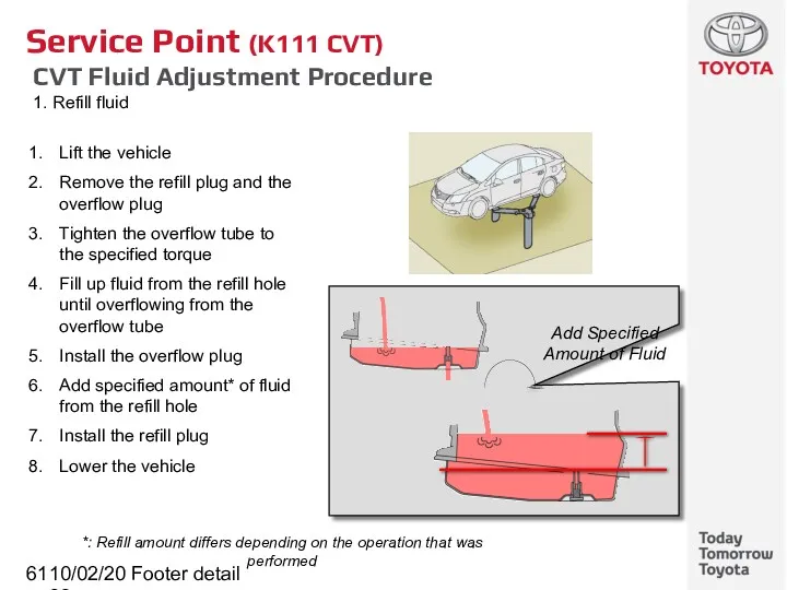
CVT Fluid Adjustment Procedure
1. Refill fluid
10/02/2022
Footer detail
Service Point (K111 CVT)
CVT Fluid Adjustment Procedure
1. Refill fluid
10/02/2022
Footer detail
Service Point (K111 CVT)
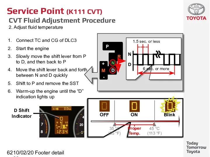
CVT Fluid Adjustment Procedure
2. Adjust fluid temperature
10/02/2022
Footer detail
Service Point (K111 CVT)
CVT Fluid Adjustment Procedure
2. Adjust fluid temperature
10/02/2022
Footer detail
Service Point (K111 CVT)
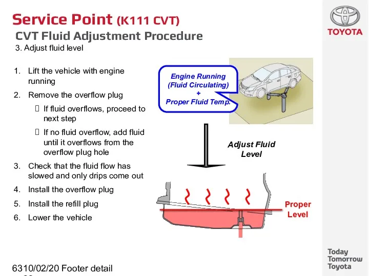
CVT Fluid Adjustment Procedure
3. Adjust fluid level
10/02/2022
Footer detail
Service Point (K111 CVT)
CVT Fluid Adjustment Procedure
3. Adjust fluid level
10/02/2022
Footer detail
K111 CVT
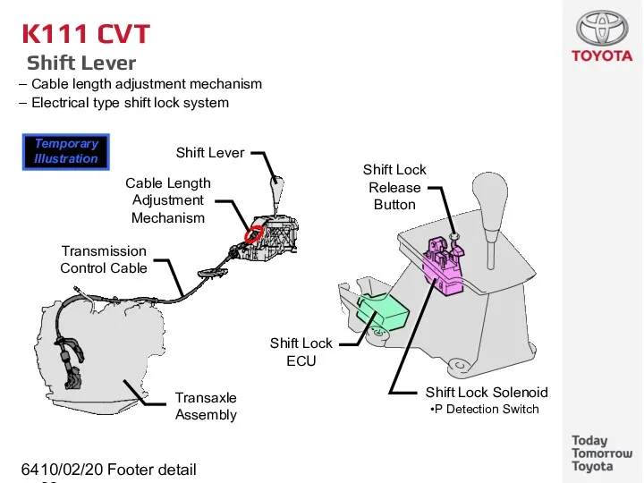
Shift Lever
Cable length adjustment mechanism
Electrical type
10/02/2022
Footer detail
K111 CVT
Shift Lever
Cable length adjustment mechanism
Electrical type
10/02/2022
Footer detail
K111 CVT
System Diagram
10/02/2022
Footer detail
K111 CVT
System Diagram
10/02/2022
Footer detail
K111 CVT
Electronic Control System
Engine-CVT Integrated Control
Neutral Control
Acceleration Improvement Control
(Linear
10/02/2022
Footer detail
K111 CVT
Electronic Control System
Engine-CVT Integrated Control
Neutral Control
Acceleration Improvement Control
(Linear
10/02/2022
Footer detail
ECM
K111 CVT
Engine-CVT Integrated Control
By communicating various signals, this control
10/02/2022
Footer detail
ECM
K111 CVT
Engine-CVT Integrated Control
By communicating various signals, this control
10/02/2022
Footer detail
K111 CVT
Acceleration Improvement Control
(Linear Feeling Improvement Control)
This control
10/02/2022
Footer detail
K111 CVT
Acceleration Improvement Control
(Linear Feeling Improvement Control)
This control
10/02/2022
Footer detail
K111 CVT
Neutral Control
When the vehicle is stopped at D
10/02/2022
Footer detail
K111 CVT
Neutral Control
When the vehicle is stopped at D
10/02/2022
Footer detail
K111 CVT
Neutral Control
Control diagram
10/02/2022
Footer detail
K111 CVT
Neutral Control
Control diagram
10/02/2022
Footer detail
K111 CVT
Shifting Control in Uphill/Downhill Traveling
For a smooth driving
10/02/2022
Footer detail
K111 CVT
Shifting Control in Uphill/Downhill Traveling
For a smooth driving
10/02/2022
Footer detail
K111 CVT
Speed Ratio Control
The target primary pulley speed is
10/02/2022
Footer detail
K111 CVT
Speed Ratio Control
The target primary pulley speed is
10/02/2022
Footer detail
K111 CVT
7-speed Sport Sequential Shiftmatic
In the M position, the
10/02/2022
Footer detail
K111 CVT
7-speed Sport Sequential Shiftmatic
In the M position, the
10/02/2022
Footer detail
K111 CVT
7-speed Sport Sequential Shiftmatic
Speed ratio is changed by
10/02/2022
Footer detail
K111 CVT
7-speed Sport Sequential Shiftmatic
Speed ratio is changed by
10/02/2022
Footer detail
K111 CVT
7-speed Sport Sequential Shiftmatic
During D position, it can
10/02/2022
Footer detail
K111 CVT
7-speed Sport Sequential Shiftmatic
During D position, it can
10/02/2022
Footer detail
K111 CVT
Lock-up Clutch Control
Wider lock-up area to improve fuel
10/02/2022
Footer detail
K111 CVT
Lock-up Clutch Control
Wider lock-up area to improve fuel
![10/02/2022 Footer detail K111 CVT Fail-safe [1/2] This function minimizes](/_ipx/f_webp&q_80&fit_contain&s_1440x1080/imagesDir/jpg/9754/slide-76.jpg)
10/02/2022
Footer detail
K111 CVT
Fail-safe [1/2]
This function minimizes the loss of operation
10/02/2022
Footer detail
K111 CVT
Fail-safe [1/2]
This function minimizes the loss of operation
![10/02/2022 Footer detail K111 CVT Fail-safe [2/2] This function minimizes](/_ipx/f_webp&q_80&fit_contain&s_1440x1080/imagesDir/jpg/9754/slide-77.jpg)
10/02/2022
Footer detail
K111 CVT
Fail-safe [2/2]
This function minimizes the loss of operation
10/02/2022
Footer detail
K111 CVT
Fail-safe [2/2]
This function minimizes the loss of operation
10/02/2022
Footer detail
Service Point (K111 CVT)
Replacement
Transaxle assembly is an assembly replacement
10/02/2022
Footer detail
Service Point (K111 CVT)
Replacement
Transaxle assembly is an assembly replacement
10/02/2022
Footer detail
Service Point (K111 CVT)
Initialization and Calibration
After replacing the following
10/02/2022
Footer detail
Service Point (K111 CVT)
Initialization and Calibration
After replacing the following
10/02/2022
Footer detail
Service Point (K111 CVT)
Initialization and Calibration
Initialization and calibration procedure
10/02/2022
Footer detail
Service Point (K111 CVT)
Initialization and Calibration
Initialization and calibration procedure
10/02/2022
Footer detail
Service Point (K111 CVT)
DTC (32 DTCs)
10/02/2022
Footer detail
Service Point (K111 CVT)
DTC (32 DTCs)
10/02/2022
Footer detail
Service Point (K111 CVT)
DTC (32 DTCs)
10/02/2022
Footer detail
Service Point (K111 CVT)
DTC (32 DTCs)
10/02/2022
Footer detail
Service Point (K111 CVT)
DATA LIST (The table below is only
10/02/2022
Footer detail
Service Point (K111 CVT)
DATA LIST (The table below is only
10/02/2022
Footer detail
Service Point (K111 CVT)
ACTIVE TEST
10/02/2022
Footer detail
Service Point (K111 CVT)
ACTIVE TEST
10/02/2022
Footer detail
K311 CVT (Continuously Variable Transaxle)
Subtitle
10/02/2022
Footer detail
K311 CVT (Continuously Variable Transaxle)
Subtitle
10/02/2022
Footer detail
K311 CVT (Continuously Variable Transaxle)
Overall
A metal belt type continuously
10/02/2022
Footer detail
K311 CVT (Continuously Variable Transaxle)
Overall
A metal belt type continuously
10/02/2022
Footer detail
K311 CVT
Components
Torque Converter with Lock-up Clutch
Continuously Variable Transaxle and Metal
10/02/2022
Footer detail
K311 CVT
Components
Torque Converter with Lock-up Clutch
Continuously Variable Transaxle and Metal
10/02/2022
Footer detail
K311 CVT
Components
10/02/2022
Footer detail
K311 CVT
Components
10/02/2022
Footer detail
K311 CVT
Major Difference Between K111 and K311
10/02/2022
Footer detail
K311 CVT
Major Difference Between K111 and K311
10/02/2022
Footer detail
K311 CVT
Identification Information
The transaxle serial number is stamped on
10/02/2022
Footer detail
K311 CVT
Identification Information
The transaxle serial number is stamped on
10/02/2022
Footer detail
K311 CVT
Torque Converter with Lock-up Clutch
Damper structure allowing lock-up
10/02/2022
Footer detail
K311 CVT
Torque Converter with Lock-up Clutch
Damper structure allowing lock-up
10/02/2022
Footer detail
K311 CVT
Oil Pump
The oil pump is combined with the
10/02/2022
Footer detail
K311 CVT
Oil Pump
The oil pump is combined with the
10/02/2022
Footer detail
K311 CVT
Gear Train
Consists of a planetary gear, continuously variable
10/02/2022
Footer detail
K311 CVT
Gear Train
Consists of a planetary gear, continuously variable
10/02/2022
Footer detail
K311 CVT
Gear Train
Operation (D Position)
10/02/2022
Footer detail
K311 CVT
Gear Train
Operation (D Position)
10/02/2022
Footer detail
K311 CVT
Gear Train
Operation (N and R Position)
N position
R position
Pulley
10/02/2022
Footer detail
K311 CVT
Gear Train
Operation (N and R Position)
N position
R position
Pulley
10/02/2022
Footer detail
K311 CVT
Continuously Variable Transaxle and Metal Belt
Performs speed ratio
10/02/2022
Footer detail
K311 CVT
Continuously Variable Transaxle and Metal Belt
Performs speed ratio
10/02/2022
Footer detail
K311 CVT
Continuously Variable Transaxle and Metal Belt
The metal belt
10/02/2022
Footer detail
K311 CVT
Continuously Variable Transaxle and Metal Belt
The metal belt
10/02/2022
Footer detail
K311 CVT
Forward and Reverse Drive Shift Mechanism
A double pinion
10/02/2022
Footer detail
K311 CVT
Forward and Reverse Drive Shift Mechanism
A double pinion
10/02/2022
Footer detail
K311 CVT
Forward and Reverse Drive Shift Mechanism
Operation
10/02/2022
Footer detail
K311 CVT
Forward and Reverse Drive Shift Mechanism
Operation
10/02/2022
Footer detail
K311 CVT
Valve Body Unit
Consists of the upper and lower
10/02/2022
Footer detail
K311 CVT
Valve Body Unit
Consists of the upper and lower
10/02/2022
Footer detail
Reference (K311 CVT)
Valve Body Unit
Hydraulic control block diagram
Secondary Pulley
Primary
10/02/2022
Footer detail
Reference (K311 CVT)
Valve Body Unit
Hydraulic control block diagram
Secondary Pulley
Primary
10/02/2022
Footer detail
K311 CVT
Valve Body Unit
Belt Clamping Pressure Control Mechanism
Belt clamping
10/02/2022
Footer detail
K311 CVT
Valve Body Unit
Belt Clamping Pressure Control Mechanism
Belt clamping
10/02/2022
Footer detail
K311 CVT
Valve Body Unit
Speed Ratio Control Mechanism
Speed ratio
10/02/2022
Footer detail
K311 CVT
Valve Body Unit
Speed Ratio Control Mechanism
Speed ratio
10/02/2022
Footer detail
K311 CVT
Speed Sensor and Pressure Sensor
3 speed sensors and
10/02/2022
Footer detail
K311 CVT
Speed Sensor and Pressure Sensor
3 speed sensors and
10/02/2022
Footer detail
K311 CVT
Parking Lock Mechanism
The parking lock mechanism locks the
10/02/2022
Footer detail
K311 CVT
Parking Lock Mechanism
The parking lock mechanism locks the
10/02/2022
Footer detail
CVT Fluid Warmer
K311 CVT
CVT Fluid Warmer
Function as fluid warmer
10/02/2022
Footer detail
CVT Fluid Warmer
K311 CVT
CVT Fluid Warmer
Function as fluid warmer
10/02/2022
Footer detail
K311 CVT
CVT Fluid
Use the Toyota Genuine CVT fluid TC
10/02/2022
Footer detail
K311 CVT
CVT Fluid
Use the Toyota Genuine CVT fluid TC
10/02/2022
Footer detail
K311 CVT
Shift Lever
Cable length adjustment mechanism
Electrical type
10/02/2022
Footer detail
K311 CVT
Shift Lever
Cable length adjustment mechanism
Electrical type
10/02/2022
Footer detail
K311 CVT
System Diagram
10/02/2022
Footer detail
K311 CVT
System Diagram
10/02/2022
Footer detail
K311 CVT
Electronic Control System
These controls are basically the same
10/02/2022
Footer detail
K311 CVT
Electronic Control System
These controls are basically the same
![10/02/2022 Footer detail K311 CVT Fail-safe [1/2] This function minimizes](/_ipx/f_webp&q_80&fit_contain&s_1440x1080/imagesDir/jpg/9754/slide-111.jpg)
10/02/2022
Footer detail
K311 CVT
Fail-safe [1/2]
This function minimizes the loss of operation
10/02/2022
Footer detail
K311 CVT
Fail-safe [1/2]
This function minimizes the loss of operation
![10/02/2022 Footer detail K311 CVT Fail-safe [2/2] This function minimizes](/_ipx/f_webp&q_80&fit_contain&s_1440x1080/imagesDir/jpg/9754/slide-112.jpg)
10/02/2022
Footer detail
K311 CVT
Fail-safe [2/2]
This function minimizes the loss of operation
10/02/2022
Footer detail
K311 CVT
Fail-safe [2/2]
This function minimizes the loss of operation
10/02/2022
Footer detail
Service Point (K311 CVT)
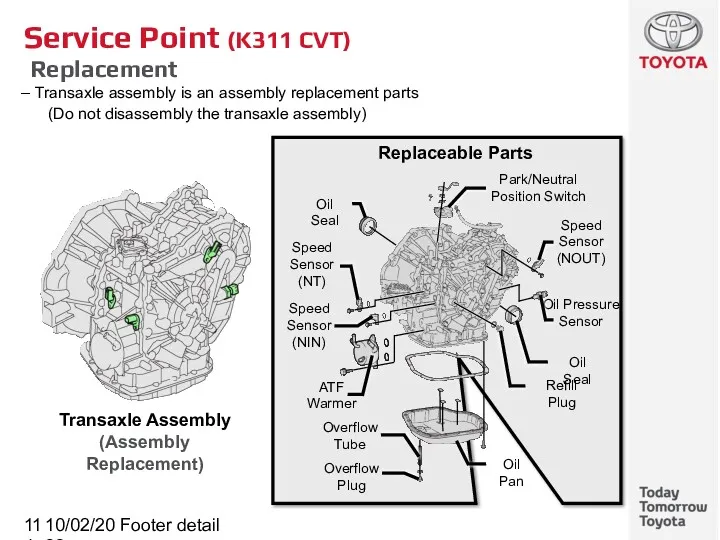
Replacement
Transaxle assembly is an assembly replacement
10/02/2022
Footer detail
Service Point (K311 CVT)
Replacement
Transaxle assembly is an assembly replacement
10/02/2022
Footer detail
Service Point (K311 CVT)
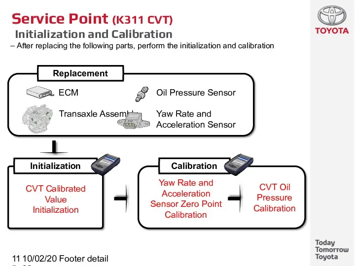
Initialization and Calibration
After replacing the following
10/02/2022
Footer detail
Service Point (K311 CVT)
Initialization and Calibration
After replacing the following

10/02/2022
Footer detail
Brake
Subtitle
10/02/2022
Footer detail
Brake
Subtitle
10/02/2022
Footer detail
Brake
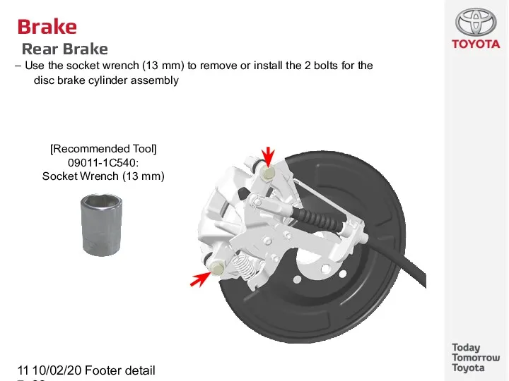
Rear Brake
Use the socket wrench (13 mm) to remove
10/02/2022
Footer detail
Brake
Rear Brake
Use the socket wrench (13 mm) to remove
10/02/2022
Footer detail
Brake
Emergency Brake Signal
This function blinks the stop light at
10/02/2022
Footer detail
Brake
Emergency Brake Signal
This function blinks the stop light at
10/02/2022
Footer detail
Brake
Emergency Brake Signal
System Diagram
Speed Sensors (x4)
Turn Signal Light
10/02/2022
Footer detail
Brake
Emergency Brake Signal
System Diagram
Speed Sensors (x4)
Turn Signal Light
10/02/2022
Footer detail
Brake
Emergency Brake Signal
Operation Condition
Operation Start Conditions
Vehicle speed is
10/02/2022
Footer detail
Brake
Emergency Brake Signal
Operation Condition
Operation Start Conditions
Vehicle speed is
10/02/2022
Footer detail
Brake Control System
Subtitle
10/02/2022
Footer detail
Brake Control System
Subtitle
10/02/2022
Footer detail
Brake Control System
Spiral Cable with Steering Angle Sensor
Absolute angle
10/02/2022
Footer detail
Brake Control System
Spiral Cable with Steering Angle Sensor
Absolute angle
10/02/2022
Footer detail
Service Point (Brake Control System)
Spiral Cable with Steering Angle Sensor
10/02/2022
Footer detail
Service Point (Brake Control System)
Spiral Cable with Steering Angle Sensor
10/02/2022
Footer detail
Electric Parking Brake
Subtitle
10/02/2022
Footer detail
Electric Parking Brake
Subtitle
10/02/2022
Footer detail
Electric Parking Brake
General
This system controls the parking brake cable
10/02/2022
Footer detail
Electric Parking Brake
General
This system controls the parking brake cable
10/02/2022
Footer detail
Electric Parking Brake
System Diagram
Electric parking brake ECU in the
10/02/2022
Footer detail
Electric Parking Brake
System Diagram
Electric parking brake ECU in the
10/02/2022
Footer detail
Electric Parking Brake
Parking Brake With Bracket Actuator Assembly
Electric parking
10/02/2022
Footer detail
Electric Parking Brake
Parking Brake With Bracket Actuator Assembly
Electric parking
10/02/2022
Footer detail
Electric Parking Brake
Parking Brake With Bracket Actuator Assembly
Lock /
10/02/2022
Footer detail
Electric Parking Brake
Parking Brake With Bracket Actuator Assembly
Lock /
10/02/2022
Footer detail
Electric Parking Brake
Parking Brake With Bracket Actuator Assembly
Tension sensor
10/02/2022
Footer detail
Electric Parking Brake
Parking Brake With Bracket Actuator Assembly
Tension sensor
10/02/2022
Footer detail
Electric Parking Brake
Electric Parking Brake Switch
To lock or release
10/02/2022
Footer detail
Electric Parking Brake
Electric Parking Brake Switch
To lock or release
10/02/2022
Footer detail
Electric Parking Brake
Clutch Pedal Stroke Sensor
The non-contact type clutch
10/02/2022
Footer detail
Electric Parking Brake
Clutch Pedal Stroke Sensor
The non-contact type clutch
10/02/2022
Footer detail
Electric Parking Brake
Clutch Pedal Stroke Sensor
There are two (main,
10/02/2022
Footer detail
Electric Parking Brake
Clutch Pedal Stroke Sensor
There are two (main,
10/02/2022
Footer detail
Electric Parking Brake
Manual Operation
The parking brake is applied or
10/02/2022
Footer detail
Electric Parking Brake
Manual Operation
The parking brake is applied or
10/02/2022
Footer detail
Electric Parking Brake
Automatic Operation
3 automatic operations
1. At Driving
When the
10/02/2022
Footer detail
Electric Parking Brake
Automatic Operation
3 automatic operations
1. At Driving
When the
10/02/2022
Footer detail
Electric Parking Brake
Drive Away Release (DAR) Function [MT Only]
This
10/02/2022
Footer detail
Electric Parking Brake
Drive Away Release (DAR) Function [MT Only]
This
10/02/2022
Footer detail
Electric Parking Brake
Manual Release
If the electric parking brake system
10/02/2022
Footer detail
Electric Parking Brake
Manual Release
If the electric parking brake system
10/02/2022
Footer detail
Service Point (Electric Parking Brake)
Initialization and Calibration
Perform initialization and
10/02/2022
Footer detail
Service Point (Electric Parking Brake)
Initialization and Calibration
Perform initialization and
10/02/2022
Footer detail
Service Point (Electric Parking Brake)
Initialization and Calibration
Clear Zero Point
10/02/2022
Footer detail
Service Point (Electric Parking Brake)
Initialization and Calibration
Clear Zero Point
10/02/2022
Footer detail
Service Point (Electric Parking Brake)
Initialization and Calibration
Yaw Rate Sensor
10/02/2022
Footer detail
Service Point (Electric Parking Brake)
Initialization and Calibration
Yaw Rate Sensor
10/02/2022
Footer detail
Service Point (Brake Control System)
Clutch Pedal Stroke Sensor
Installation (new)
1.
10/02/2022
Footer detail
Service Point (Brake Control System)
Clutch Pedal Stroke Sensor
Installation (new)
1.
10/02/2022
Footer detail
Service Point (Brake Control System)
Brake Pedal Stroke Sensor
Installation (reuse)
1.
10/02/2022
Footer detail
Service Point (Brake Control System)
Brake Pedal Stroke Sensor
Installation (reuse)
1.
10/02/2022
Footer detail
Electric Parking Brake
Full Release Mode
Use full release mode when
10/02/2022
Footer detail
Electric Parking Brake
Full Release Mode
Use full release mode when
![10/02/2022 Footer detail Electric Parking Brake DTC [1/2]](/_ipx/f_webp&q_80&fit_contain&s_1440x1080/imagesDir/jpg/9754/slide-142.jpg)
10/02/2022
Footer detail
Electric Parking Brake
DTC [1/2]
10/02/2022
Footer detail
Electric Parking Brake
DTC [1/2]
![10/02/2022 Footer detail Electric Parking Brake DTC [2/2]](/_ipx/f_webp&q_80&fit_contain&s_1440x1080/imagesDir/jpg/9754/slide-143.jpg)
10/02/2022
Footer detail
Electric Parking Brake
DTC [2/2]
10/02/2022
Footer detail
Electric Parking Brake
DTC [2/2]
10/02/2022
Footer detail
Electric Parking Brake
Active Test
10/02/2022
Footer detail
Electric Parking Brake
Active Test

10/02/2022
Footer detail
Steering
Subtitle
10/02/2022
Footer detail
Steering
Subtitle
10/02/2022
Footer detail
Steering Column Assembly
3-phase Brushless Motor with Rotational Angle Sensor
Reduction Mechanism
Hall
10/02/2022
Footer detail
Steering Column Assembly
3-phase Brushless Motor with Rotational Angle Sensor
Reduction Mechanism
Hall
10/02/2022
Footer detail
Steering
System Diagram
10/02/2022
Footer detail
Steering
System Diagram
10/02/2022
Footer detail
Steering
Major Difference From COROLLA / AURIS
10/02/2022
Footer detail
Steering
Major Difference From COROLLA / AURIS
10/02/2022
Footer detail
Steering
Electric Load Control
In order to prevent reduction of EPS
10/02/2022
Footer detail
Steering
Electric Load Control
In order to prevent reduction of EPS
 Фазы вещества. Фазовые переходы
 Основы зонной теории твердого тела
 20231003_prezentatsiya
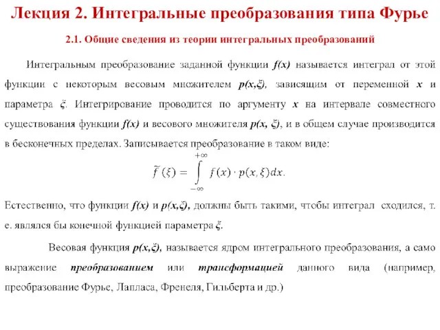 Интегральные преобразования типа Фурье. Общие сведения из теории интегральных преобразований
 Урок мастерская Конвекция 8 класс вторая часть
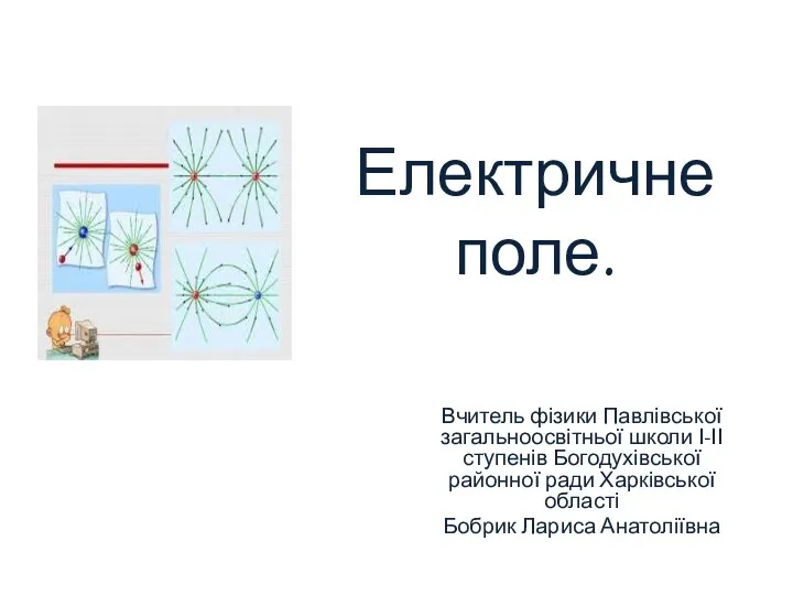 Електричне поле. Електрична сила
 Диэлектрики в электростатическом поле
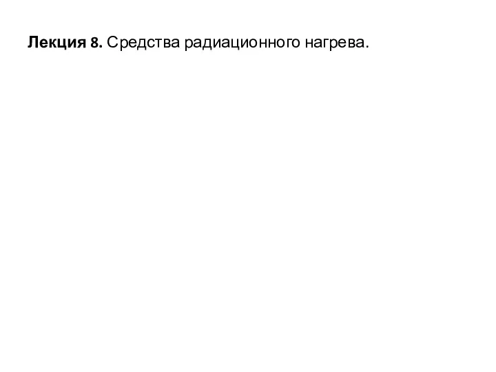 Средства радиационного нагрева
 Закон Ома для участка цепи
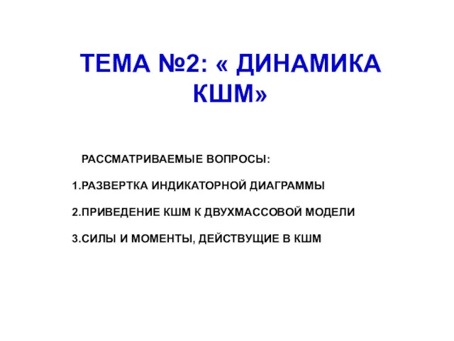 Динамика КШМ, часть 1. Лекция №2
 Щелочные аккумуляторы
 Axles and shafts
 Різновиди механізмів натиску листових друкарських машин
 Анализ вариантов составляющих конструкции из КМ силового элемента втулки РВ вертолета
 Проектування розвитку електричної мережі 110 кВ Полтавської області
 Неисправности буксовых узлов
 Судовые двигатели
 Урок-конференция Атомная энергетика: проблемы экологии 11 класс
 Динамика. Законы Ньютона
 Презентация Тест 11 класс. Итог
 Основное электрооборудование станций и подстанций. (Лекция 2)
 Середня швидкість. Нерівномірний рух
 Кристаллические и аморфные тела. 10 класс
 Топливная система HPI
 Источники излучения на АЭС
 Филворд Тела для 7 класса по физике
 Физика – наука о природе. Современная физика – наука, изучающая общие свойства материи – вещества и поля
 Судовые электроэнергетические системы. Содержание программы ГИА