- 2D Pipe Junction. Introduction to ANSYS ICEM CFD

Содержание
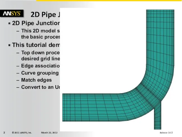
- 2. 2D Pipe Junction This 2D model starts you out simple, but shows the basic process and
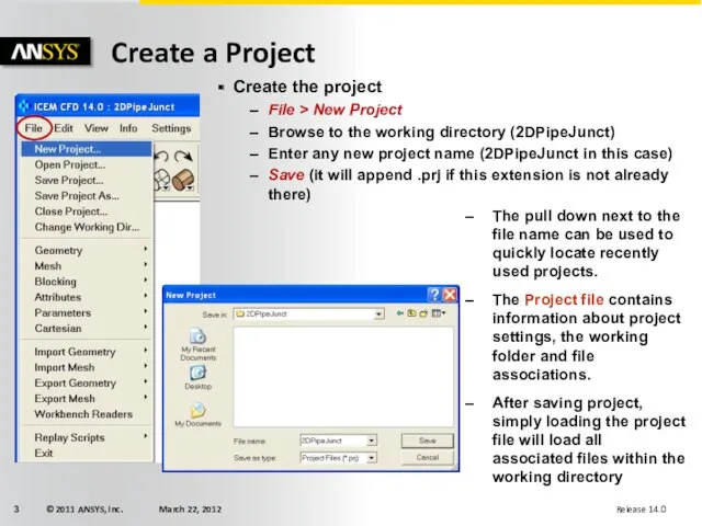
- 3. Create a Project The pull down next to the file name can be used to quickly
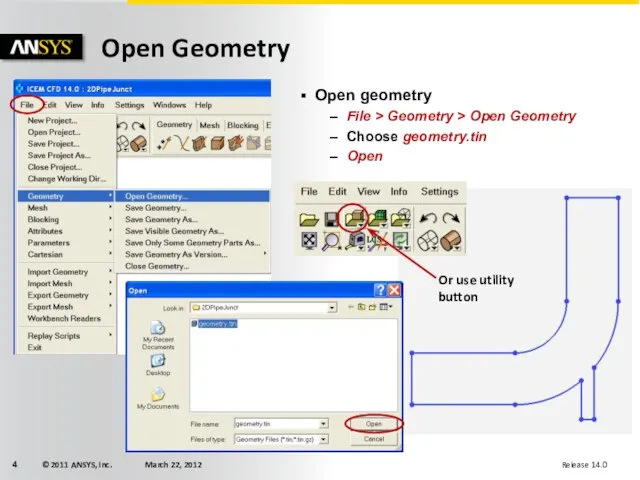
- 4. Open Geometry Open geometry File > Geometry > Open Geometry Choose geometry.tin Open Or use utility
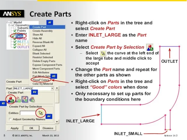
- 5. Create Parts INLET_LARGE INLET_SMALL OUTLET Right-click on Parts in the tree and select Create Part Enter
- 6. Often, students just split wherever there are lines or features This does not necessarily produce good
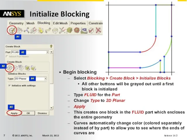
- 7. Initialize Blocking #4 #1 #5 #3 Begin blocking Select Blocking > Create Block > Initialize Blocks
- 8. Splitting blocks Select Blocking > Split Block > Split Block Select the Select edges(s) button and
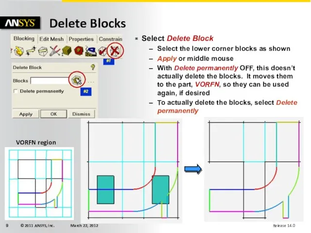
- 9. Delete Blocks #1 #2 Select Delete Block Select the lower corner blocks as shown Apply or
- 10. Associate vertices to points Turn on Points in the model tree Select Blocking > Associate >
- 11. 1 edge 2 curves 1 edge 2 curves Select Blocking > Associate > Associate Edge to
- 12. Displaying Associations Look for big arrows. Incorrect associations will have large arrows when vertices are on
- 13. Grouping Curves 1 2 3 Alternatively: Group curves before associating edges (not necessary for this exercise)
- 14. Associate remaining edges Optional Turn off Curves temporarily to view only Edges Straight edges that lie
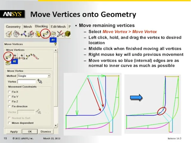
- 15. Move Vertices onto Geometry #1 #2 Move remaining vertices Select Move Vertex > Move Vertex Left
- 16. Set hexa sizes on curves Select Mesh > Curve Mesh Setup Press Select curve(s) button to
- 17. Update Sizes The mesh sizes on the geometry need to be transferred to the blocking edges
- 18. Compute Pre-Mesh Pre mesh with No projection Select Pre-Mesh in the model tree Select Yes to
- 19. Edge Parameters Select Blocking > Pre-Mesh Params > Edge Params Press the Select edge(s) button and
- 20. Edge Parameters (Continued) Press the Select edge(s) button and select the edge shown Set Spacing 1
- 21. Matching Edges Select Blocking > Pre-Mesh Params > Match Edges Select the Reference Edge as shown
- 22. Convert to Unstructured Mesh The pre-mesh cannot be written to the solver yet Right mouse click
- 23. Select Solver Select Output > Select Solver Press the pulldown arrow next to the Output Solver
- 24. Boundary Conditions Select Output > Boundary Conditions The tree structure is organized according to the dimensions
- 26. Скачать презентацию
2D Pipe Junction
This 2D model starts you out simple, but shows
2D Pipe Junction
This 2D model starts you out simple, but shows
Create a Project
The pull down next to the file name can
Create a Project
The pull down next to the file name can
Open Geometry
Open geometry
File > Geometry > Open Geometry
Choose geometry.tin
Open
Or use utility
Open Geometry
Open geometry
File > Geometry > Open Geometry
Choose geometry.tin
Open
Or use utility
Create Parts
INLET_LARGE
INLET_SMALL
OUTLET
Right-click on Parts in the tree and select Create Part
Enter
Create Parts
INLET_LARGE
INLET_SMALL
OUTLET
Right-click on Parts in the tree and select Create Part
Enter
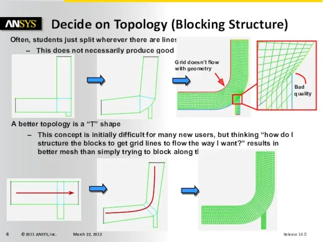
Often, students just split wherever there are lines or features
This does
Often, students just split wherever there are lines or features
This does
Initialize Blocking
#4
#1
#5
#3
Begin blocking
Select Blocking > Create Block > Initialize Blocks
All other
Initialize Blocking
#4
#1
#5
#3
Begin blocking
Select Blocking > Create Block > Initialize Blocks
All other
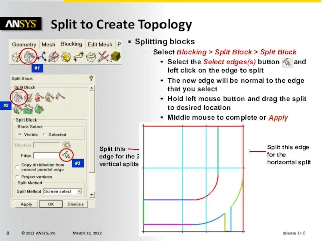
Splitting blocks
Select Blocking > Split Block > Split Block
Select the Select
Splitting blocks
Select Blocking > Split Block > Split Block
Select the Select
Delete Blocks
#1
#2
Select Delete Block
Select the lower corner blocks as shown
Apply or
Delete Blocks
#1
#2
Select Delete Block
Select the lower corner blocks as shown
Apply or
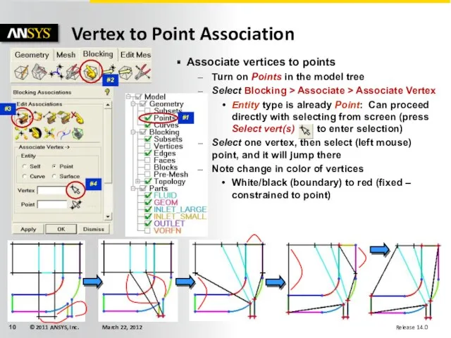
Associate vertices to points
Turn on Points in the model tree
Select Blocking
Associate vertices to points
Turn on Points in the model tree
Select Blocking
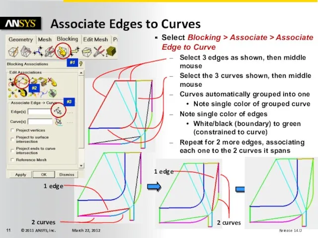
1 edge
2 curves
1 edge
2 curves
Select Blocking > Associate > Associate Edge
1 edge
2 curves
1 edge
2 curves
Select Blocking > Associate > Associate Edge
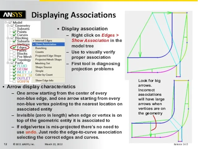
Displaying Associations
Look for big arrows.
Incorrect associations will have large arrows when
Displaying Associations
Look for big arrows.
Incorrect associations will have large arrows when
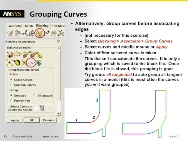
Grouping Curves
1
2
3
Alternatively: Group curves before associating edges
(not necessary for this exercise)
Select
Grouping Curves
1
2
3
Alternatively: Group curves before associating edges
(not necessary for this exercise)
Select
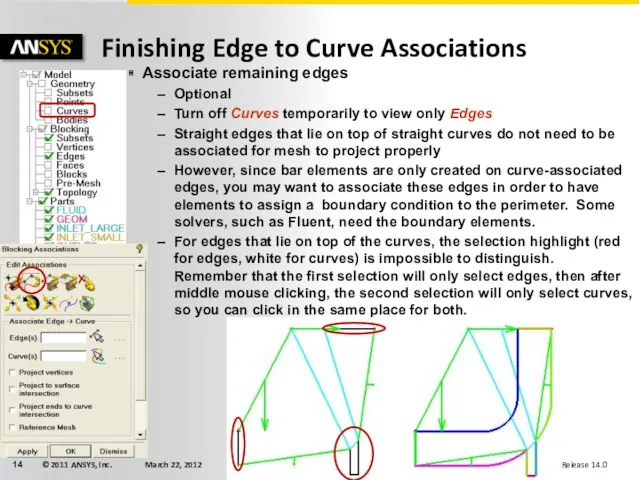
Associate remaining edges
Optional
Turn off Curves temporarily to view only Edges
Straight edges
Associate remaining edges
Optional
Turn off Curves temporarily to view only Edges
Straight edges
Move Vertices onto Geometry
#1
#2
Move remaining vertices
Select Move Vertex > Move Vertex
Left
Move Vertices onto Geometry
#1
#2
Move remaining vertices
Select Move Vertex > Move Vertex
Left
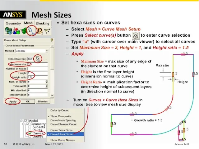
Set hexa sizes on curves
Select Mesh > Curve Mesh Setup
Press Select
Set hexa sizes on curves
Select Mesh > Curve Mesh Setup
Press Select
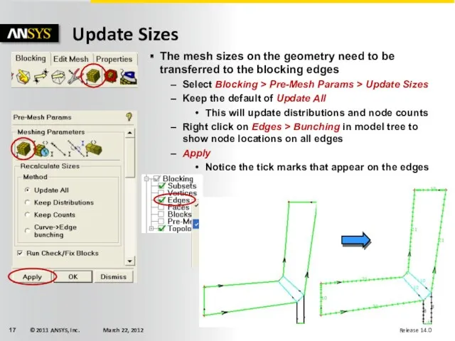
Update Sizes
The mesh sizes on the geometry need to be transferred
Update Sizes
The mesh sizes on the geometry need to be transferred
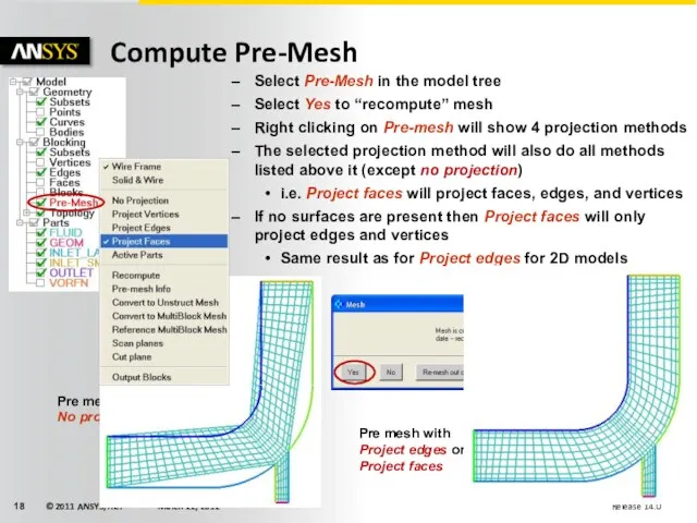
Compute Pre-Mesh
Pre mesh with No projection
Select Pre-Mesh in the model tree
Select
Compute Pre-Mesh
Pre mesh with No projection
Select Pre-Mesh in the model tree
Select
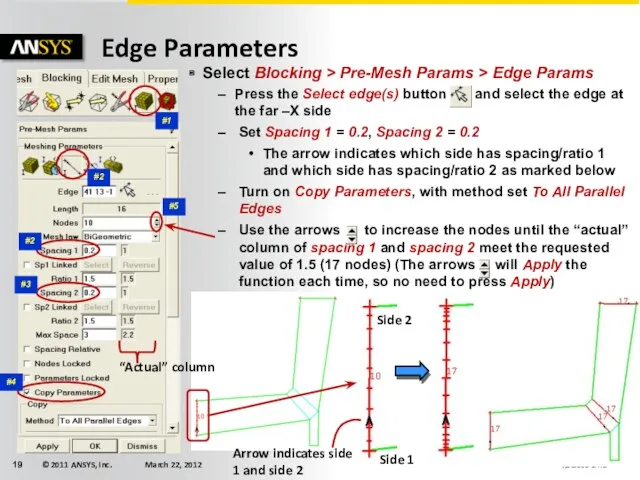
Edge Parameters
Select Blocking > Pre-Mesh Params > Edge Params
Press the Select
Edge Parameters
Select Blocking > Pre-Mesh Params > Edge Params
Press the Select
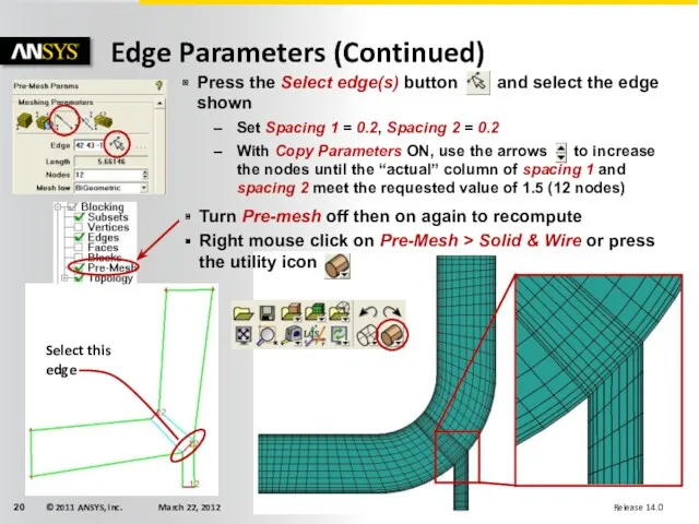
Edge Parameters (Continued)
Press the Select edge(s) button and select the edge
Edge Parameters (Continued)
Press the Select edge(s) button and select the edge
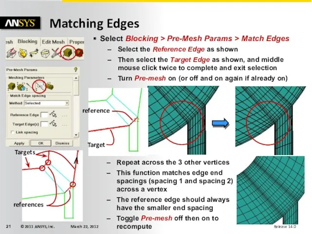
Matching Edges
Select Blocking > Pre-Mesh Params > Match Edges
Select the Reference
Matching Edges
Select Blocking > Pre-Mesh Params > Match Edges
Select the Reference
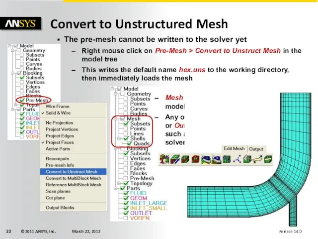
Convert to Unstructured Mesh
The pre-mesh cannot be written to the solver
Convert to Unstructured Mesh
The pre-mesh cannot be written to the solver
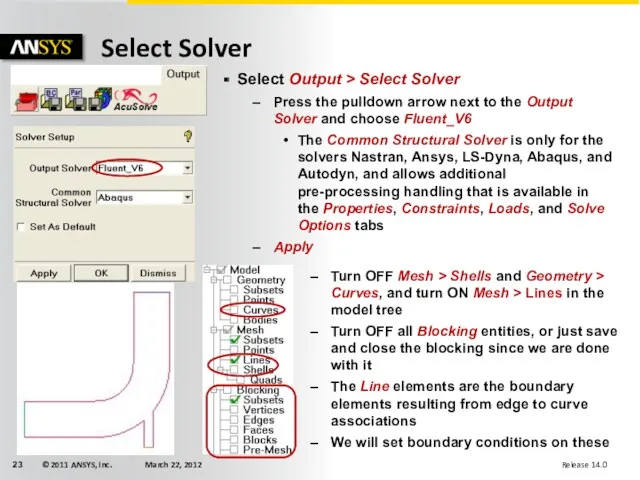
Select Solver
Select Output > Select Solver
Press the pulldown arrow next to
Select Solver
Select Output > Select Solver
Press the pulldown arrow next to
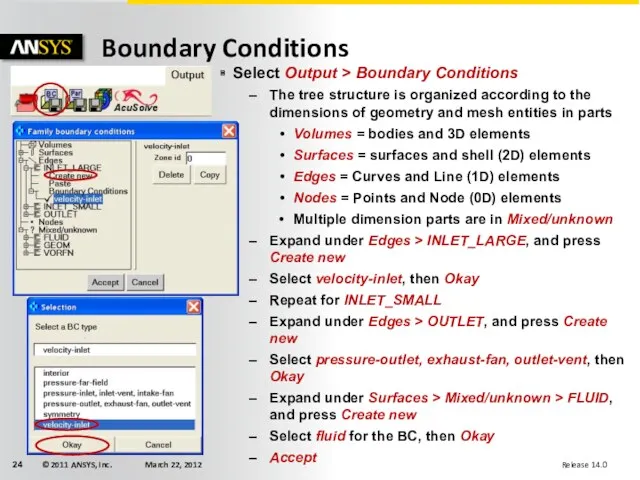
Boundary Conditions
Select Output > Boundary Conditions
The tree structure is organized according
Boundary Conditions
Select Output > Boundary Conditions
The tree structure is organized according
 Подзапросы в SQL
 Многоуровневые списки
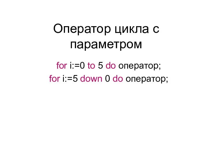 Оператор цикла с параметром
 Database. Lection 3
 Таблицы
 Ajax. Генератор кода для вставки на сайт
 Функции в С++
 Стегосистемы для других покрывающих сообщений. Лекция 4
 Введение в операционные системы
 Роль СМИ в политической жизни общества
 Моделирование ВС. Модели массового обслуживания. (Тема 3.2)
 Пять игр развивающих интеллект, для взрослых
 Компьютерные презентации
 Обзор онлайн аудитории Беларуси
 Spring Boot. Spring Data. ORM
 Методическая разработка внеклассного мероприятия Турнир знатоков Информатики Внеклассное мероприятие по информатике для учащихся 6-го класса Внеклассное мероприятие по информатике для учащихся 6-го класса Турнир знатоков ИНФОРМАТ
 Языки программирования C++
 Рекурсивті тәртіптерді анықтау және GNU. Prolog қолдану
 Здоровье-сберегающие технологии на уроках информатики
 SAP HANA – платформа для бизнеса в реальном времени
 Форматы_графических_файлов
 Поиск информации в Интернете
 Мобильді құрылғыларға арналған операциялық жүйелер
 Обработка информации и алгоритмы
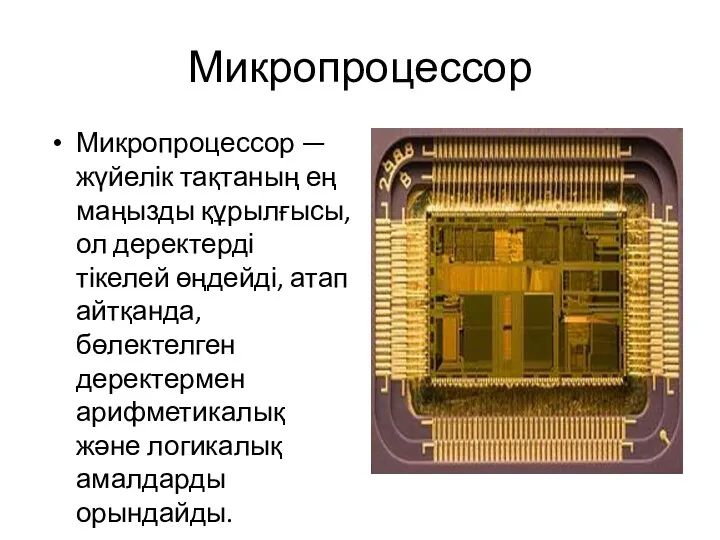 Микропроцессор
 Навчальні проекти
 Lecture 11. Even more normalization
 WEB-Index: Аудитория интернет-проектов. Desktop, Октябрь 2017, Москва