- Chapter 1 Introduction

Содержание
- 2. Chapter 1: introduction Chapter goal: Get “feel,” “big picture,” introduction to terminology more depth, detail later
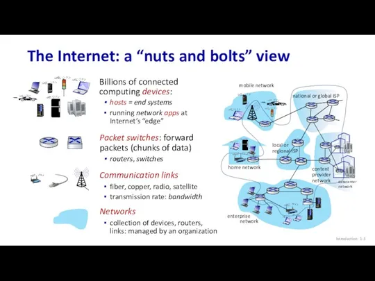
- 3. Internet The Internet: a “nuts and bolts” view Introduction: 1-
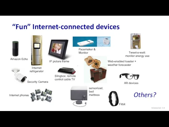
- 4. “Fun” Internet-connected devices Introduction: 1- IP picture frame Web-enabled toaster + weather forecaster Internet phones Slingbox:
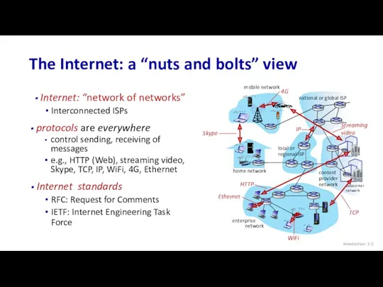
- 5. Internet: “network of networks” Interconnected ISPs The Internet: a “nuts and bolts” view Introduction: 1- mobile
- 6. Infrastructure that provides services to applications: Web, streaming video, multimedia teleconferencing, email, games, e-commerce, social media,
- 7. What’s a protocol? Introduction: 1- Human protocols: “what’s the time?” “I have a question” introductions …
- 8. What’s a protocol? Introduction: 1- A human protocol and a computer network protocol: Q: other human
- 9. Chapter 1: roadmap Introduction: 1- What is the Internet? What is a protocol? Network edge: hosts,
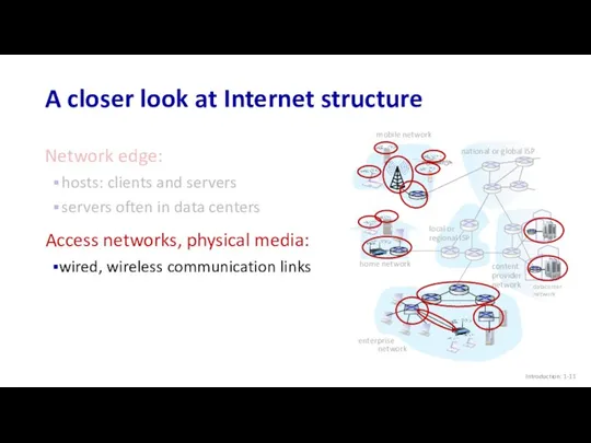
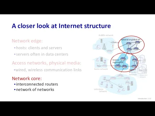
- 10. A closer look at Internet structure Introduction: 1- Network edge: hosts: clients and servers servers often
- 11. A closer look at Internet structure Introduction: 1- mobile network home network enterprise network national or
- 12. A closer look at Internet structure Network edge: hosts: clients and servers servers often in data
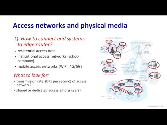
- 13. Access networks and physical media Introduction: 1- mobile network home network enterprise network national or global
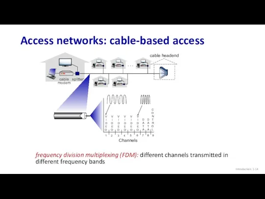
- 14. Access networks: cable-based access Introduction: 1- cable modem splitter … cable headend frequency division multiplexing (FDM):
- 15. Access networks: cable-based access Introduction: 1- cable modem splitter … cable headend HFC: hybrid fiber coax
- 16. Introduction: 1- Access networks: digital subscriber line (DSL) central office telephone network DSLAM use existing telephone
- 17. Introduction: 1- Access networks: home networks to/from headend or central office wireless devices
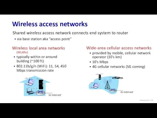
- 18. Introduction: 1- Wireless access networks Shared wireless access network connects end system to router via base
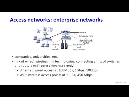
- 19. Introduction: 1- Access networks: enterprise networks companies, universities, etc. mix of wired, wireless link technologies, connecting
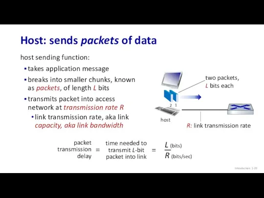
- 20. Introduction: 1- Host: sends packets of data host sending function: takes application message breaks into smaller
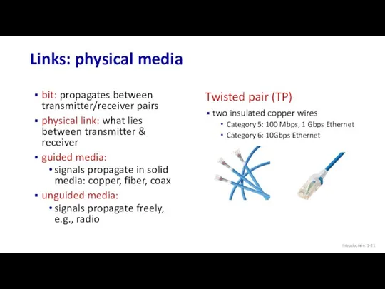
- 21. Introduction: 1- Links: physical media bit: propagates between transmitter/receiver pairs physical link: what lies between transmitter
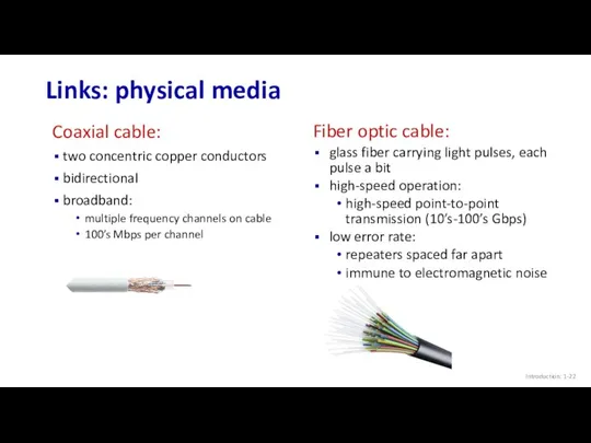
- 22. Introduction: 1- Links: physical media Coaxial cable: two concentric copper conductors bidirectional broadband: multiple frequency channels
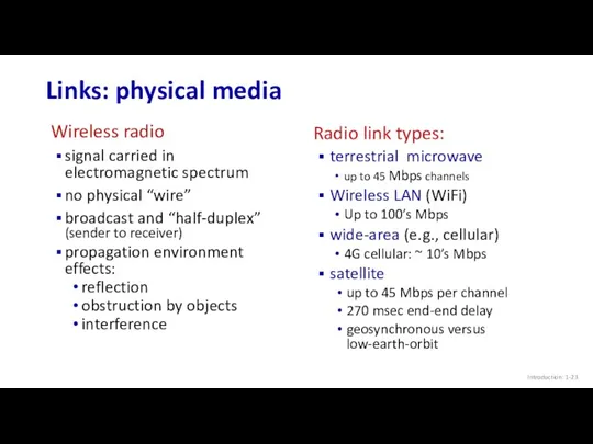
- 23. Introduction: 1- Links: physical media Wireless radio signal carried in electromagnetic spectrum no physical “wire” broadcast
- 24. Chapter 1: roadmap Introduction: 1- What is the Internet? What is a protocol? Network edge: hosts,
- 25. The network core mesh of interconnected routers packet-switching: hosts break application-layer messages into packets forward packets
- 26. Packet-switching: store-and-forward Transmission delay: takes L/R seconds to transmit (push out) L-bit packet into link at
- 27. Packet-switching: queueing delay, loss Packet queuing and loss: if arrival rate (in bps) to link exceeds
- 28. Two key network-core functions Introduction: 1- Forwarding: local action: move arriving packets from router’s input link
- 29. Alternative to packet switching: circuit switching end-end resources allocated to, reserved for “call” between source and
- 30. Circuit switching: FDM and TDM Introduction: 1- Frequency Division Multiplexing (FDM) optical, electromagnetic frequencies divided into
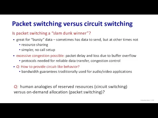
- 31. Packet switching versus circuit switching Introduction: 1- Example: 1 Gb/s link each user: 100 Mb/s when
- 32. Packet switching versus circuit switching Introduction: 1- great for “bursty” data – sometimes has data to
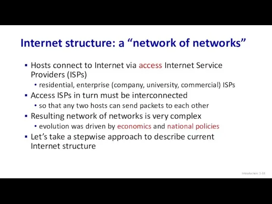
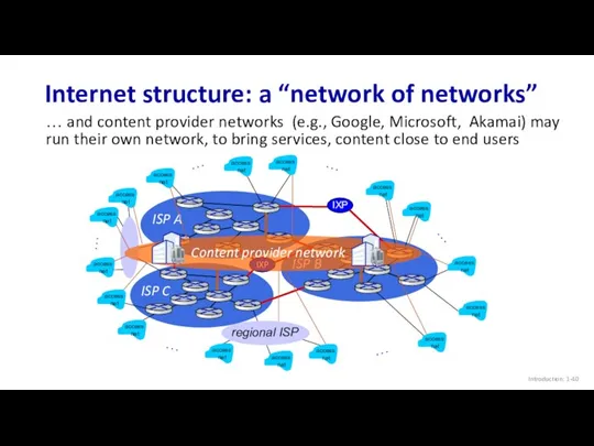
- 33. Internet structure: a “network of networks” Hosts connect to Internet via access Internet Service Providers (ISPs)
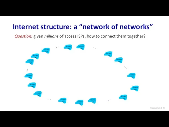
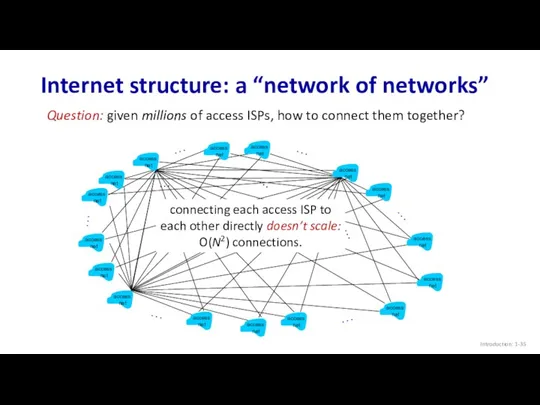
- 34. Internet structure: a “network of networks” Introduction: 1- Question: given millions of access ISPs, how to
- 35. Internet structure: a “network of networks” Introduction: 1- Question: given millions of access ISPs, how to
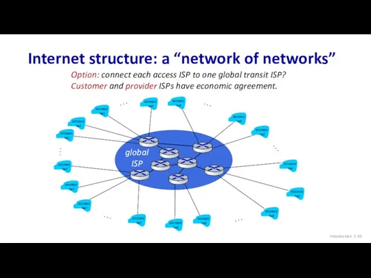
- 36. Internet structure: a “network of networks” Introduction: 1- Option: connect each access ISP to one global
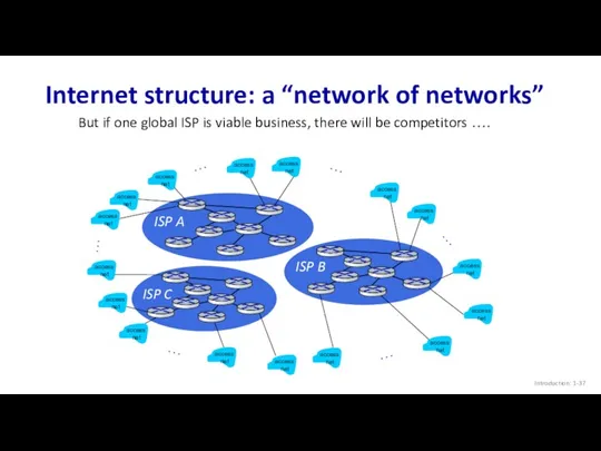
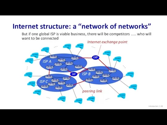
- 37. ISP A ISP C ISP B Internet structure: a “network of networks” Introduction: 1- But if
- 38. ISP A ISP C ISP B Internet structure: a “network of networks” Introduction: 1- But if
- 39. ISP A ISP C ISP B Internet structure: a “network of networks” Introduction: 1- … …
- 40. ISP A ISP C ISP B Internet structure: a “network of networks” Introduction: 1- … …
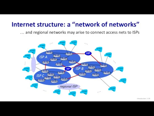
- 41. Internet structure: a “network of networks” Introduction: 1- Tier 1 ISP Tier 1 ISP Regional ISP
- 42. Tier-1 ISP Network map: Sprint (2019) Introduction: 1-
- 43. Chapter 1: roadmap Introduction: 1- What is the Internet? What is a protocol? Network edge: hosts,
- 44. How do packet loss and delay occur? Introduction: 1- packets queue in router buffers packets queue,
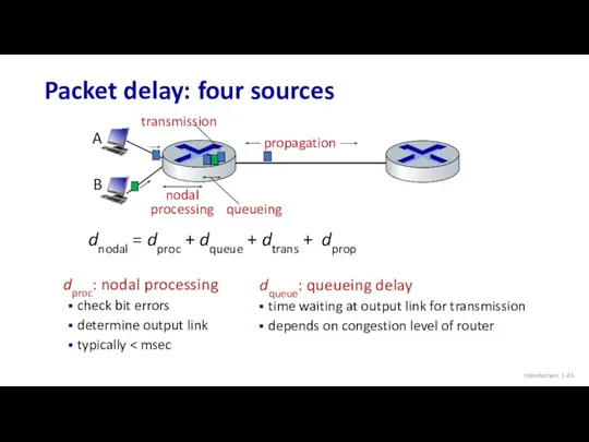
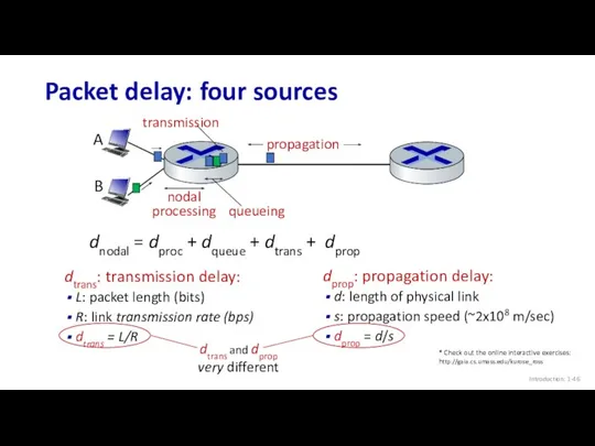
- 45. Packet delay: four sources Introduction: 1- dproc: nodal processing check bit errors determine output link typically
- 46. Packet delay: four sources Introduction: 1- propagation nodal processing queueing dnodal = dproc + dqueue +
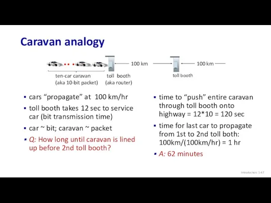
- 47. Caravan analogy Introduction: 1- cars “propagate” at 100 km/hr toll booth takes 12 sec to service
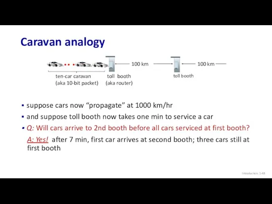
- 48. Caravan analogy Introduction: 1- ten-car caravan (aka 10-bit packet) 100 km 100 km suppose cars now
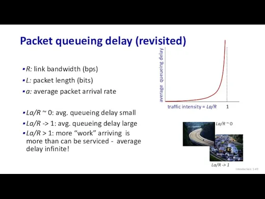
- 49. Packet queueing delay (revisited) Introduction: 1- R: link bandwidth (bps) L: packet length (bits) a: average
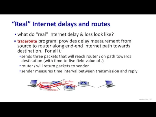
- 50. “Real” Internet delays and routes Introduction: 1- what do “real” Internet delay & loss look like?
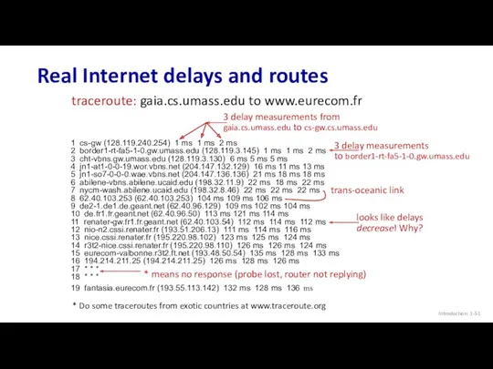
- 51. Real Internet delays and routes Introduction: 1- 1 cs-gw (128.119.240.254) 1 ms 1 ms 2 ms
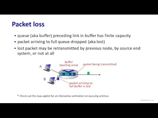
- 52. Packet loss Introduction: 1- queue (aka buffer) preceding link in buffer has finite capacity A B
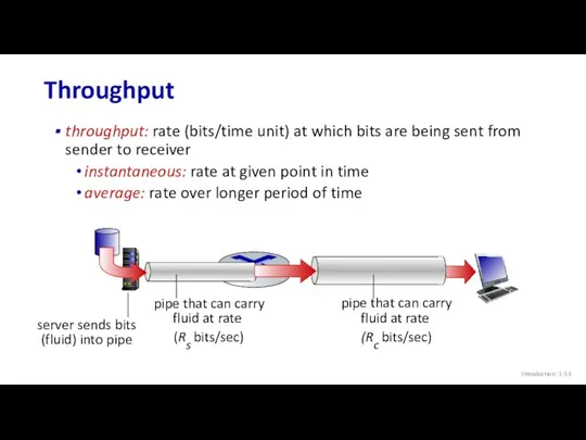
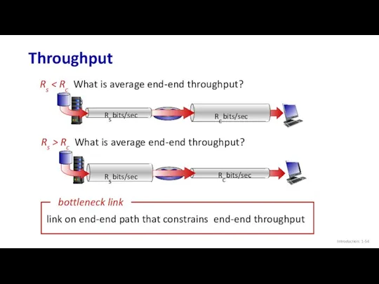
- 53. Throughput Introduction: 1- throughput: rate (bits/time unit) at which bits are being sent from sender to
- 54. Throughput Introduction: 1- Rs Rs bits/sec Rs > Rc What is average end-end throughput?
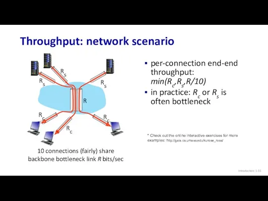
- 55. Throughput: network scenario Introduction: 1-
- 56. Chapter 1: roadmap Introduction: 1- What is the Internet? What is a protocol? Network edge: hosts,
- 57. Network security Introduction: 1- field of network security: how bad guys can attack computer networks how
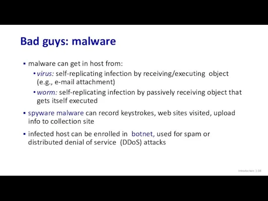
- 58. Bad guys: malware Introduction: 1- malware can get in host from: virus: self-replicating infection by receiving/executing
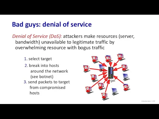
- 59. Bad guys: denial of service Introduction: 1- Denial of Service (DoS): attackers make resources (server, bandwidth)
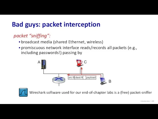
- 60. Bad guys: packet interception Introduction: 1- packet “sniffing”: broadcast media (shared Ethernet, wireless) promiscuous network interface
- 61. Bad guys: fake identity Introduction: 1- IP spoofing: send packet with false source address A B
- 62. Chapter 1: roadmap Introduction: 1- What is the Internet? What is a protocol? Network edge: hosts,
- 63. Protocol “layers” and reference models Introduction: 1- Networks are complex, with many “pieces”: hosts routers links
- 64. Example: organization of air travel Introduction: 1- airline travel: a series of steps, involving many services
- 65. Example: organization of air travel Introduction: 1- ticket (purchase) baggage (check) gates (load) runway takeoff airplane
- 66. Why layering? Introduction: 1- dealing with complex systems: explicit structure allows identification, relationship of complex system’s
- 67. Internet protocol stack Introduction: 1- application: supporting network applications IMAP, SMTP, HTTP transport: process-process data transfer
- 68. Encapsulation Introduction: 1- source application transport network link physical segment datagram destination application transport network link
- 69. Chapter 1: roadmap Introduction: 1- What is the Internet? What is a protocol? Network edge: hosts,
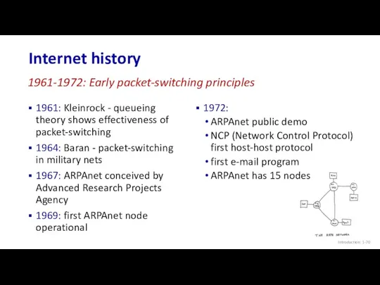
- 70. Internet history Introduction: 1- 1961: Kleinrock - queueing theory shows effectiveness of packet-switching 1964: Baran -
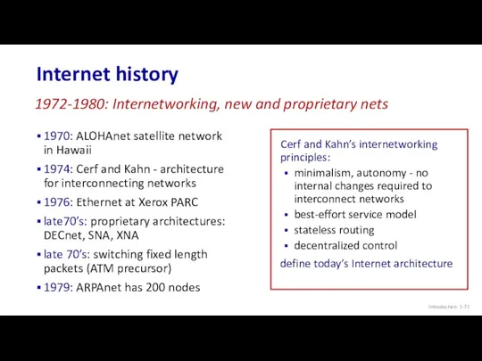
- 71. Internet history Introduction: 1- 1970: ALOHAnet satellite network in Hawaii 1974: Cerf and Kahn - architecture
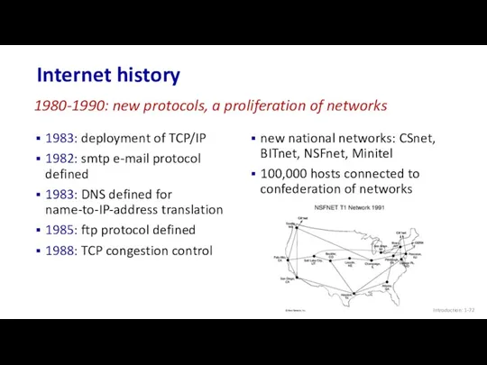
- 72. Internet history Introduction: 1- 1983: deployment of TCP/IP 1982: smtp e-mail protocol defined 1983: DNS defined
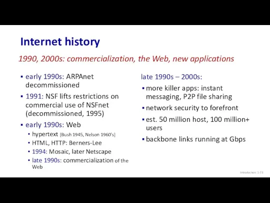
- 73. Internet history Introduction: 1- early 1990s: ARPAnet decommissioned 1991: NSF lifts restrictions on commercial use of
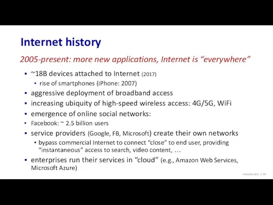
- 74. Internet history Introduction: 1- ~18B devices attached to Internet (2017) rise of smartphones (iPhone: 2007) aggressive
- 75. Chapter 1: summary Introduction: 1- We’ve covered a “ton” of material! Internet overview what’s a protocol?
- 76. Additional Chapter 1 slides Introduction: 1-
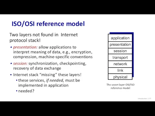
- 77. ISO/OSI reference model Introduction: 1- Two layers not found in Internet protocol stack! presentation: allow applications
- 79. Скачать презентацию
Chapter 1: introduction
Chapter goal:
Get “feel,” “big picture,” introduction to terminology
more
Chapter 1: introduction
Chapter goal:
Get “feel,” “big picture,” introduction to terminology
more
Internet
The Internet: a “nuts and bolts” view
Introduction: 1-
Internet
The Internet: a “nuts and bolts” view
Introduction: 1-
“Fun” Internet-connected devices
Introduction: 1-
IP picture frame
Web-enabled toaster +
weather forecaster
Internet phones
Slingbox: remote
control
“Fun” Internet-connected devices
Introduction: 1-
IP picture frame
Web-enabled toaster +
weather forecaster
Internet phones
Slingbox: remote
control
Internet: “network of networks”
Interconnected ISPs
The Internet: a “nuts and bolts” view
Introduction:
Internet: “network of networks”
Interconnected ISPs
The Internet: a “nuts and bolts” view
Introduction:
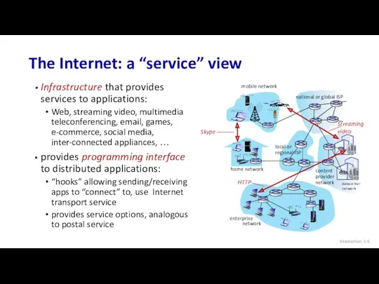
Infrastructure that provides services to applications:
Web, streaming video, multimedia teleconferencing, email,
Infrastructure that provides services to applications:
Web, streaming video, multimedia teleconferencing, email,
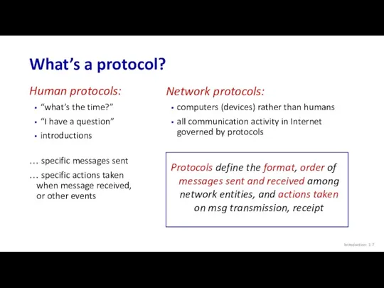
What’s a protocol?
Introduction: 1-
Human protocols:
“what’s the time?”
“I have a question”
introductions
… specific
What’s a protocol?
Introduction: 1-
Human protocols:
“what’s the time?”
“I have a question”
introductions
… specific
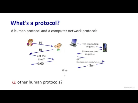
What’s a protocol?
Introduction: 1-
A human protocol and a computer network protocol:
Q:
What’s a protocol?
Introduction: 1-
A human protocol and a computer network protocol:
Q:

Chapter 1: roadmap
Introduction: 1-
What is the Internet?
What is a protocol?
Network edge:
Chapter 1: roadmap
Introduction: 1-
What is the Internet?
What is a protocol?
Network edge:
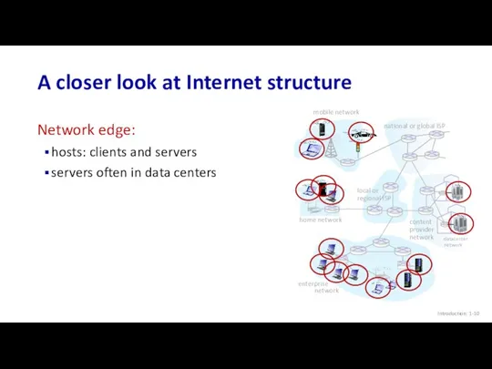
A closer look at Internet structure
Introduction: 1-
Network edge:
hosts: clients and servers
servers
A closer look at Internet structure
Introduction: 1-
Network edge:
hosts: clients and servers
servers
A closer look at Internet structure
Introduction: 1-
mobile network
home network
enterprise
network
national or
A closer look at Internet structure
Introduction: 1-
mobile network
home network
enterprise
network
national or
A closer look at Internet structure
Network edge:
hosts: clients and servers
servers often
A closer look at Internet structure
Network edge:
hosts: clients and servers
servers often
Access networks and physical media
Introduction: 1-
mobile network
home network
enterprise
network
national or global
Access networks and physical media
Introduction: 1-
mobile network
home network
enterprise
network
national or global
Access networks: cable-based access
Introduction: 1-
cable
modem
splitter
…
cable headend
frequency division multiplexing (FDM): different channels
Access networks: cable-based access
Introduction: 1-
cable
modem
splitter
…
cable headend
frequency division multiplexing (FDM): different channels
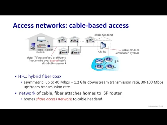
Access networks: cable-based access
Introduction: 1-
cable
modem
splitter
…
cable headend
HFC: hybrid fiber coax
asymmetric: up to
Access networks: cable-based access
Introduction: 1-
cable
modem
splitter
…
cable headend
HFC: hybrid fiber coax
asymmetric: up to
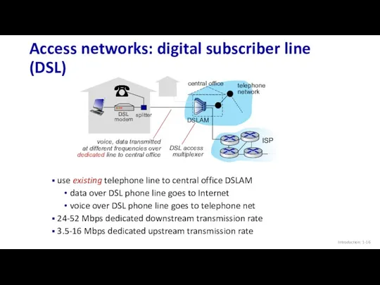
Introduction: 1-
Access networks: digital subscriber line (DSL)
central office
telephone
network
DSLAM
use existing telephone line
Introduction: 1-
Access networks: digital subscriber line (DSL)
central office
telephone
network
DSLAM
use existing telephone line
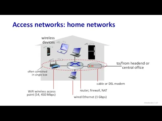
Introduction: 1-
Access networks: home networks
to/from headend or central office
wireless
devices
Introduction: 1-
Access networks: home networks
to/from headend or central office
wireless
devices
Introduction: 1-
Wireless access networks
Shared wireless access network connects end system to
Introduction: 1-
Wireless access networks
Shared wireless access network connects end system to
Introduction: 1-
Access networks: enterprise networks
companies, universities, etc.
mix of wired, wireless link
Introduction: 1-
Access networks: enterprise networks
companies, universities, etc.
mix of wired, wireless link
Introduction: 1-
Host: sends packets of data
host sending function:
takes application message
breaks into
Introduction: 1-
Host: sends packets of data
host sending function:
takes application message
breaks into
Introduction: 1-
Links: physical media
bit: propagates between
transmitter/receiver pairs
physical link: what lies between
Introduction: 1-
Links: physical media
bit: propagates between
transmitter/receiver pairs
physical link: what lies between
Introduction: 1-
Links: physical media
Coaxial cable:
two concentric copper conductors
bidirectional
broadband:
multiple frequency channels on
Introduction: 1-
Links: physical media
Coaxial cable:
two concentric copper conductors
bidirectional
broadband:
multiple frequency channels on
Introduction: 1-
Links: physical media
Wireless radio
signal carried in electromagnetic spectrum
no physical “wire”
broadcast
Introduction: 1-
Links: physical media
Wireless radio
signal carried in electromagnetic spectrum
no physical “wire”
broadcast

Chapter 1: roadmap
Introduction: 1-
What is the Internet?
What is a protocol?
Network edge:
Chapter 1: roadmap
Introduction: 1-
What is the Internet?
What is a protocol?
Network edge:
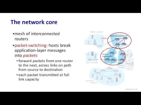
The network core
mesh of interconnected routers
packet-switching: hosts break application-layer messages into
The network core
mesh of interconnected routers
packet-switching: hosts break application-layer messages into
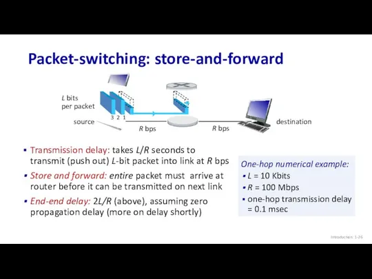
Packet-switching: store-and-forward
Transmission delay: takes L/R seconds to transmit (push out) L-bit
Packet-switching: store-and-forward
Transmission delay: takes L/R seconds to transmit (push out) L-bit
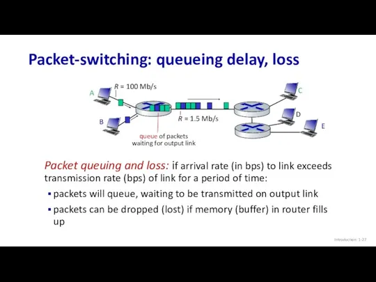
Packet-switching: queueing delay, loss
Packet queuing and loss: if arrival rate (in
Packet-switching: queueing delay, loss
Packet queuing and loss: if arrival rate (in
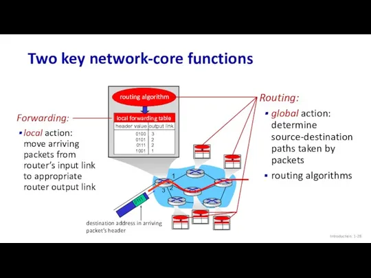
Two key network-core functions
Introduction: 1-
Forwarding:
local action: move arriving packets from
Two key network-core functions
Introduction: 1-
Forwarding:
local action: move arriving packets from
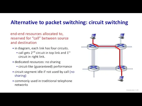
Alternative to packet switching: circuit switching
end-end resources allocated to, reserved for
Alternative to packet switching: circuit switching
end-end resources allocated to, reserved for
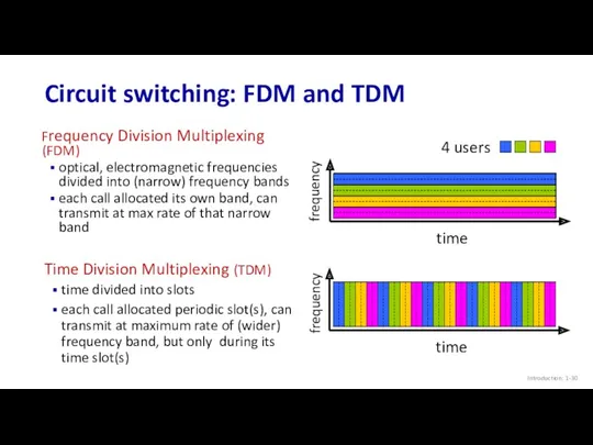
Circuit switching: FDM and TDM
Introduction: 1-
Frequency Division Multiplexing (FDM)
optical, electromagnetic frequencies
Circuit switching: FDM and TDM
Introduction: 1-
Frequency Division Multiplexing (FDM)
optical, electromagnetic frequencies
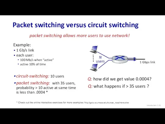
Packet switching versus circuit switching
Introduction: 1-
Example:
1 Gb/s link
each user:
100 Mb/s
Packet switching versus circuit switching
Introduction: 1-
Example:
1 Gb/s link
each user:
100 Mb/s
Packet switching versus circuit switching
Introduction: 1-
great for “bursty” data – sometimes
Packet switching versus circuit switching
Introduction: 1-
great for “bursty” data – sometimes
Internet structure: a “network of networks”
Hosts connect to Internet via access
Internet structure: a “network of networks”
Hosts connect to Internet via access
Internet structure: a “network of networks”
Introduction: 1-
Question: given millions of access
Internet structure: a “network of networks”
Introduction: 1-
Question: given millions of access
Internet structure: a “network of networks”
Introduction: 1-
Question: given millions of access
Internet structure: a “network of networks”
Introduction: 1-
Question: given millions of access
Internet structure: a “network of networks”
Introduction: 1-
Option: connect each access ISP
Internet structure: a “network of networks”
Introduction: 1-
Option: connect each access ISP
ISP A
ISP C
ISP B
Internet structure: a “network of networks”
Introduction: 1-
But if
ISP A
ISP C
ISP B
Internet structure: a “network of networks”
Introduction: 1-
But if
ISP A
ISP C
ISP B
Internet structure: a “network of networks”
Introduction: 1-
But if
ISP A
ISP C
ISP B
Internet structure: a “network of networks”
Introduction: 1-
But if
ISP A
ISP C
ISP B
Internet structure: a “network of networks”
Introduction: 1-
…
…
…
…
…
…
… and
ISP A
ISP C
ISP B
Internet structure: a “network of networks”
Introduction: 1-
…
…
…
…
…
…
… and
ISP A
ISP C
ISP B
Internet structure: a “network of networks”
Introduction: 1-
…
…
…
…
…
…
… and
ISP A
ISP C
ISP B
Internet structure: a “network of networks”
Introduction: 1-
…
…
…
…
…
…
… and
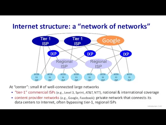
Internet structure: a “network of networks”
Introduction: 1-
Tier 1 ISP
Tier 1 ISP
Regional
Internet structure: a “network of networks”
Introduction: 1-
Tier 1 ISP
Tier 1 ISP
Regional
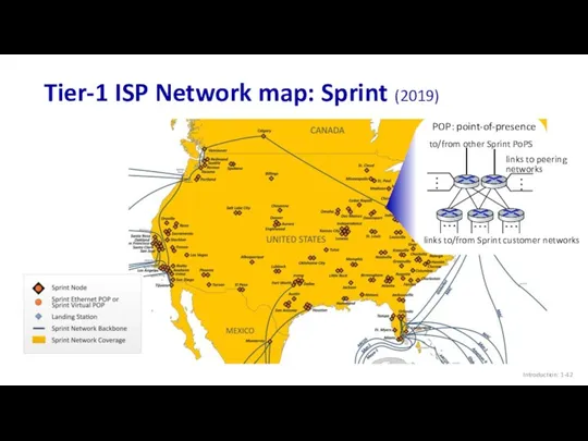
Tier-1 ISP Network map: Sprint (2019)
Introduction: 1-
Tier-1 ISP Network map: Sprint (2019)
Introduction: 1-

Chapter 1: roadmap
Introduction: 1-
What is the Internet?
What is a protocol?
Network edge:
Chapter 1: roadmap
Introduction: 1-
What is the Internet?
What is a protocol?
Network edge:
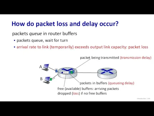
How do packet loss and delay occur?
Introduction: 1-
packets queue in router
How do packet loss and delay occur?
Introduction: 1-
packets queue in router
Packet delay: four sources
Introduction: 1-
dproc: nodal processing
check bit errors
determine output
Packet delay: four sources
Introduction: 1-
dproc: nodal processing
check bit errors
determine output
Packet delay: four sources
Introduction: 1-
propagation
nodal
processing
queueing
dnodal = dproc + dqueue + dtrans
Packet delay: four sources
Introduction: 1-
propagation
nodal
processing
queueing
dnodal = dproc + dqueue + dtrans
Caravan analogy
Introduction: 1-
cars “propagate” at 100 km/hr
toll booth takes 12 sec
Caravan analogy
Introduction: 1-
cars “propagate” at 100 km/hr
toll booth takes 12 sec
Caravan analogy
Introduction: 1-
ten-car caravan
(aka 10-bit packet)
100 km
100 km
suppose cars now “propagate”
Caravan analogy
Introduction: 1-
ten-car caravan
(aka 10-bit packet)
100 km
100 km
suppose cars now “propagate”
Packet queueing delay (revisited)
Introduction: 1-
R: link bandwidth (bps)
L: packet length (bits)
a:
Packet queueing delay (revisited)
Introduction: 1-
R: link bandwidth (bps)
L: packet length (bits)
a:
“Real” Internet delays and routes
Introduction: 1-
what do “real” Internet delay &
“Real” Internet delays and routes
Introduction: 1-
what do “real” Internet delay &
Real Internet delays and routes
Introduction: 1-
1 cs-gw (128.119.240.254) 1 ms 1
Real Internet delays and routes
Introduction: 1-
1 cs-gw (128.119.240.254) 1 ms 1
Packet loss
Introduction: 1-
queue (aka buffer) preceding link in buffer has finite
Packet loss
Introduction: 1-
queue (aka buffer) preceding link in buffer has finite
Throughput
Introduction: 1-
throughput: rate (bits/time unit) at which bits are being sent
Throughput
Introduction: 1-
throughput: rate (bits/time unit) at which bits are being sent
Throughput
Introduction: 1-
Rs < Rc What is average end-end throughput?
Rs bits/sec
Rs
Throughput
Introduction: 1-
Rs < Rc What is average end-end throughput?
Rs bits/sec
Rs
Throughput: network scenario
Introduction: 1-
Throughput: network scenario
Introduction: 1-
Chapter 1: roadmap
Introduction: 1-
What is the Internet?
What is a protocol?
Network edge:
Chapter 1: roadmap
Introduction: 1-
What is the Internet?
What is a protocol?
Network edge:
Network security
Introduction: 1-
field of network security:
how bad guys can attack computer
Network security
Introduction: 1-
field of network security:
how bad guys can attack computer
Bad guys: malware
Introduction: 1-
malware can get in host from:
virus: self-replicating
Bad guys: malware
Introduction: 1-
malware can get in host from:
virus: self-replicating
Bad guys: denial of service
Introduction: 1-
Denial of Service (DoS): attackers make
Bad guys: denial of service
Introduction: 1-
Denial of Service (DoS): attackers make
Bad guys: packet interception
Introduction: 1-
packet “sniffing”:
broadcast media (shared Ethernet, wireless)
promiscuous
Bad guys: packet interception
Introduction: 1-
packet “sniffing”:
broadcast media (shared Ethernet, wireless)
promiscuous
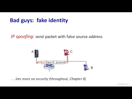
Bad guys: fake identity
Introduction: 1-
IP spoofing: send packet with false source
Bad guys: fake identity
Introduction: 1-
IP spoofing: send packet with false source

Chapter 1: roadmap
Introduction: 1-
What is the Internet?
What is a protocol?
Network edge:
Chapter 1: roadmap
Introduction: 1-
What is the Internet?
What is a protocol?
Network edge:
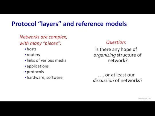
Protocol “layers” and reference models
Introduction: 1-
Networks are complex,
with many “pieces”:
hosts
routers
links of
Protocol “layers” and reference models
Introduction: 1-
Networks are complex,
with many “pieces”:
hosts
routers
links of
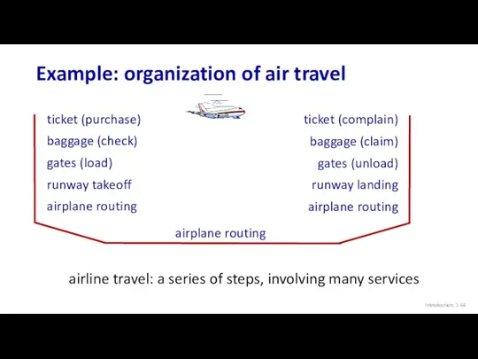
Example: organization of air travel
Introduction: 1-
airline travel: a series of steps,
Example: organization of air travel
Introduction: 1-
airline travel: a series of steps,
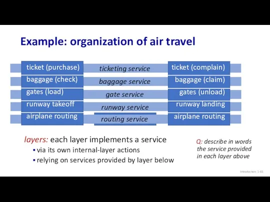
Example: organization of air travel
Introduction: 1-
ticket (purchase)
baggage (check)
gates (load)
runway takeoff
airplane routing
ticket
Example: organization of air travel
Introduction: 1-
ticket (purchase)
baggage (check)
gates (load)
runway takeoff
airplane routing
ticket
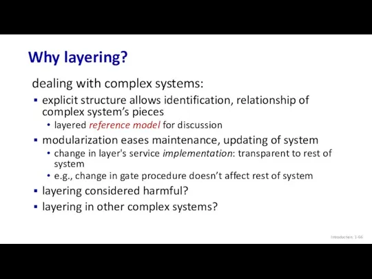
Why layering?
Introduction: 1-
dealing with complex systems:
explicit structure allows identification, relationship of
Why layering?
Introduction: 1-
dealing with complex systems:
explicit structure allows identification, relationship of
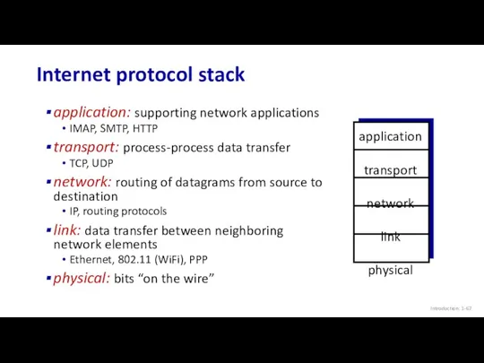
Internet protocol stack
Introduction: 1-
application: supporting network applications
IMAP, SMTP, HTTP
transport: process-process data
Internet protocol stack
Introduction: 1-
application: supporting network applications
IMAP, SMTP, HTTP
transport: process-process data
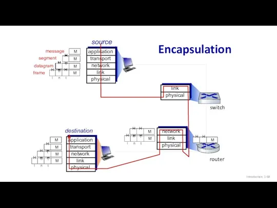
Encapsulation
Introduction: 1-
source
application
transport
network
link
physical
segment
datagram
destination
application
transport
network
link
physical
router
switch
message
frame
Encapsulation
Introduction: 1-
source
application
transport
network
link
physical
segment
datagram
destination
application
transport
network
link
physical
router
switch
message
frame
Chapter 1: roadmap
Introduction: 1-
What is the Internet?
What is a protocol?
Network edge:
Chapter 1: roadmap
Introduction: 1-
What is the Internet?
What is a protocol?
Network edge:
Internet history
Introduction: 1-
1961: Kleinrock - queueing theory shows effectiveness of packet-switching
1964:
Internet history
Introduction: 1-
1961: Kleinrock - queueing theory shows effectiveness of packet-switching
1964:
Internet history
Introduction: 1-
1970: ALOHAnet satellite network in Hawaii
1974: Cerf and Kahn
Internet history
Introduction: 1-
1970: ALOHAnet satellite network in Hawaii
1974: Cerf and Kahn
Internet history
Introduction: 1-
1983: deployment of TCP/IP
1982: smtp e-mail protocol defined
1983:
Internet history
Introduction: 1-
1983: deployment of TCP/IP
1982: smtp e-mail protocol defined
1983:
Internet history
Introduction: 1-
early 1990s: ARPAnet decommissioned
1991: NSF lifts restrictions on commercial
Internet history
Introduction: 1-
early 1990s: ARPAnet decommissioned
1991: NSF lifts restrictions on commercial
Internet history
Introduction: 1-
~18B devices attached to Internet (2017)
rise of smartphones (iPhone:
Internet history
Introduction: 1-
~18B devices attached to Internet (2017)
rise of smartphones (iPhone:
Chapter 1: summary
Introduction: 1-
We’ve covered a “ton” of material!
Internet overview
what’s a
Chapter 1: summary
Introduction: 1-
We’ve covered a “ton” of material!
Internet overview
what’s a

Additional Chapter 1 slides
Introduction: 1-
Additional Chapter 1 slides
Introduction: 1-
ISO/OSI reference model
Introduction: 1-
Two layers not found in Internet protocol stack!
presentation:
ISO/OSI reference model
Introduction: 1-
Two layers not found in Internet protocol stack!
presentation:
 Интеллектуальная игра Хакеры
 3 класс Обработка информации
 1С-Коннект. Технология продажи и подключения сервиса
 Ассистенты или чат - боты
 Волоконно-оптические линии связи
 Представление числовой информации с помощью систем счисления
 Второй уровень информационного взаимодействия. Вторичные информационные процессы
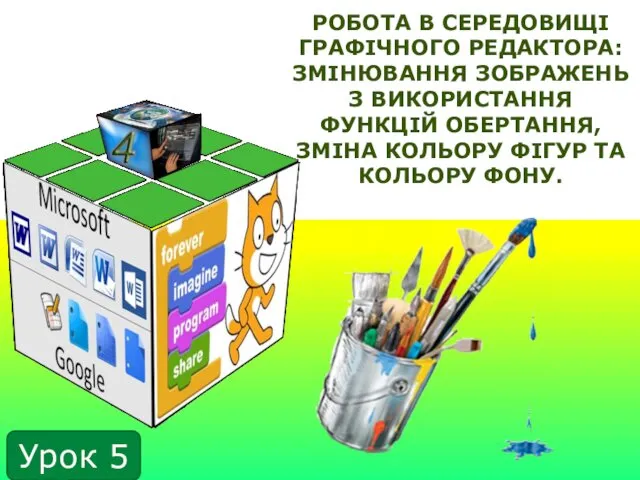 Робота в середовищі графічного редактора: змінювання зображень з використання функцій обертання, зміна кольору фігур та кольору
 Введение в JavaScript. Лекция 16
 Обработка текстовой информации
 Системы контроля версий
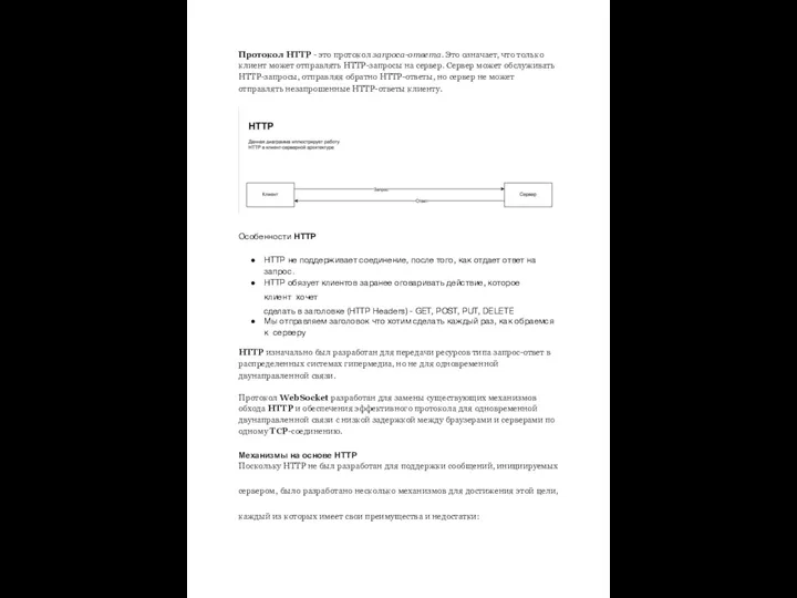 Протокол HTTP - это протокол запроса-ответа
 Учет затрат и расчет себестоимости для МСФО
 Проектирование ИС
 Устройство компьютера
 Тестирование удобства использования
 IMD Vista Industrial Measurement Devices
 20231109_tablichnyy_sposob_resh._logich._zadach
 Крипке құрылымы әсер ететін жүйелердің моделі ретінде
 Дизайн компьютерных игр и анимационных фильмов с точки зрения их визуального воздействия на человека
 Архитектура ЭВМ и вычислительных систем
 Инструкция по электронной записи в Муниципальное учреждение Спортивная школа Виктория
 Web Technology
 Интернет-технологии в социальной работе
 Разработка интеграционного модуля выгрузки данных о продажах фотосепараторов на корпоративный сайт ООО Сисорт
 Зустріч лідерів
 Операторы ввода, вывода в языке Си
 Основы программирования на языке Java