- Finite Element Analysis Using Abaqus

Содержание
- 2. Abaqus Basics Simulation Abaqus/Standard Output file: Job.odb, job.dat Postprocessing Abaqus/CAE Analysis Input file Input file (text):
- 3. Methods of Analysis in ABAQUS Interactive mode Create an FE model and analysis using GUI Advantage:
- 4. Methods of Analysis in ABAQUS Analysis input file ABAQUS solver reads an analysis input file Possible
- 5. Components in ABAQUS Model Geometry modeling (define geometry) Creating nodes and elements (discretization) Element section properties
- 6. FEM Modeling
- 7. FEM Modeling Which analysis type? Which element type? Section properties Material properties Loads and boundary conditions
- 8. Line (Beam element) - Assign section properties (area, moment of inertia) - Assign material properties Volume
- 9. FEM Modeling Line (Beam element) - Apply distributed load “on the line” - Apply fixed BC
- 10. FEM Modeling Line (Beam element) - Discretized geometry with beam element - Discretized BC and load
- 11. Start Abaqus/CAE Startup window
- 12. Example: Overhead Hoist
- 13. Units Abaqus does not have built-in units Users must use consistent units
- 14. Create Part Parts Create 2D Planar, Deformable, Wire, Approx size = 4.0 Provide complete constrains and
- 15. Geometry Constraint Define exact geometry Add constraints Add dimension Over constraint warning
- 16. Geometry Modification Modify geometry modeling 1. Go back to the sketch 2. Update geometry
- 17. Define Material Properties Materials Name: Steel Mechanical Elasticity Elastic
- 18. Define Section Properties Calculate cross-sectional area using CLI (diameter = 5mm) Sections Name: Circular_Section Beam, Truss
- 19. Define Section Properties Assign the section to the part Section Assignments Select all wires Assign Circular_Section
- 20. Assembly and Analysis Step Different parts can be assembled in a model Single assembly per model
- 21. Assembly and Analysis Step Examine Field Output Request (automatically requested) User can change the request
- 22. Boundary Conditions Boundary conditions: Displacements or rotations are known BCs Name: Fixed Step: Initial Category: Mechanical
- 23. Applied Loads Loads Name: Force Step: Applied Load Category: Mechanical Type: Concentrated force Choose lower-center point
- 24. Meshing the Model Parts Part-1, Mesh Menu Mesh, Element Types (side menu ) Select all wireframes
- 25. Meshing the Model Seed a mesh Control how to mesh (element size, etc) Menu Seed, Part
- 26. Mesh Modification Menu Seed, Part (side menu ) Change the seed size (Global size) 1.0 to
- 27. Creating an Analysis Job Jobs Jobs, Truss Data Check Monitor Continue (or, submit)
- 28. Postprocessing Change “Model” tab to “Results” tab Menu File, Open Job.odb file Common Plot Option (side
- 29. Postprocessing Deformation scale Common Plot Option (side menu ), click on the Basic tab, Deformation Scale
- 30. Postprocessing Tools, XY Data, Manager Position: Integration Point Stress components, S11 (Try with displacements and reaction)
- 31. Postprocessing Click on the Elements/Nodes tab Select Element/Nodes you want to see result and save Click
- 32. Postprocessing Report, Field Output Position: Integration Point Stress components, S11 (Try with displacements and reaction) Default
- 34. Скачать презентацию
 Современные формы интернет-коммуникаций
 Игры со стратегией
 Венгерские кроссворды на уроках информатики
 Visual Basic
 База данных
 Основы языка HTML
 Software development life cycle
 Работа с зацепками в системе Youla для МПП
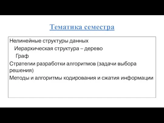 Нелинейные структуры данных. Лекция 1
 Інформаційні системи та технології
 Check-in
 Создание презентаций в Microsoft Power Point
 Программирование на Python
 Современные компьютерные технологии социального моделирования
 4 декабря - день информатики в России
 Сетевой архив проектно-сметной документации
 Последовательность
 Условия выбора и сложные логические выражения. 9 класс
 Обучение Microsoft® Word 2010
 Обережно – шахрайство
 Комбинаторика и программирование
 Базова конфігурація комп’ютера. Будова комп’ютера
 Преобразования типов. Лекция 4
 Tails/ The amnesic in cognito live system
 Тренинг Умные лендинги 2.0. Оформление текста
 Условный оператор на языке Pascal
 Программирование разветвляющихся алгоритмов. Начала программирования на языке Python. Информатика. 8 класс
 Управление насосной станцией. Программирование в LOGO! Soft Comfort