- Введение в Verilog. Стандартные этапы проектирования устройства на FPGA

Содержание
- 2. Стандартные этапы проектирования устройства на FPGA Ввод описания проекта Моделирование, преобразование пользовательского описания в компоненты и
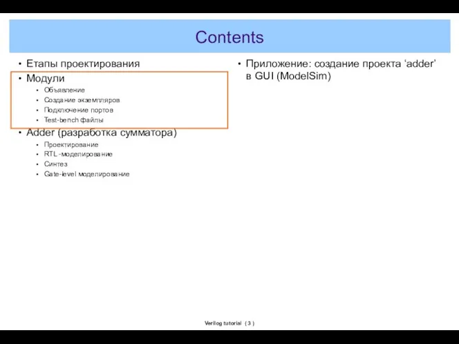
- 3. Verilog tutorial ( ) Contents Етапы проектирования Модули Объявление Создание экземпляров Подключение портов Test-bench файлы Adder
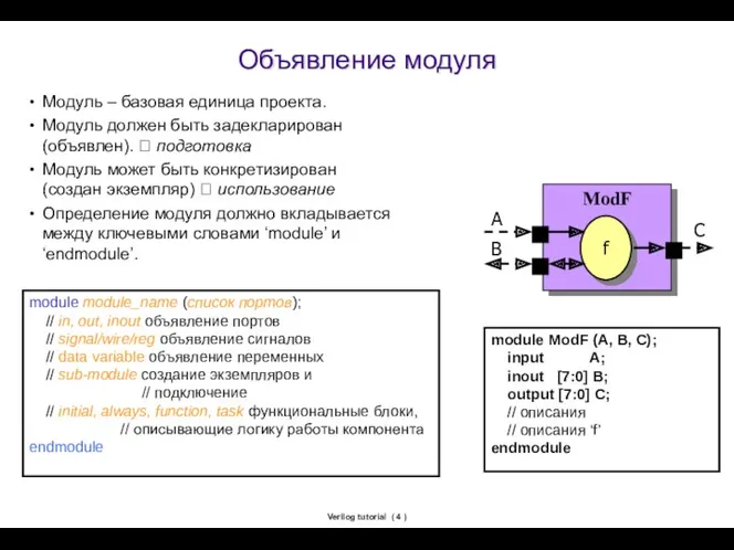
- 4. Verilog tutorial ( ) Объявление модуля Модуль – базовая единица проекта. Модуль должен быть задекларирован (объявлен).
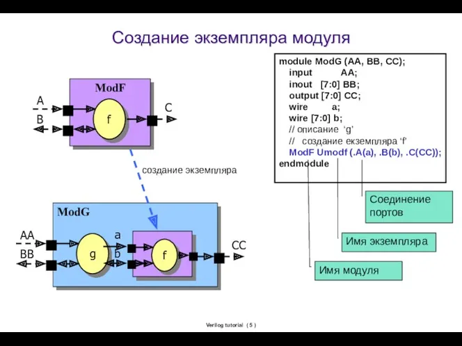
- 5. Verilog tutorial ( ) Создание экземпляра модуля module ModG (AA, BB, CC); input AA; inout [7:0]
- 6. Соединение портов Позиционный принцип – сопоставление портов в объявлении модуля и в его экземпляре: module ModF
- 7. Типы данных Типы данных Verilog Net - соединение (связь, цепь) wire – простой провод wand, wor
- 8. Introduction to Verilog Basic ( ) Nets (2/2) wire Y; // declaration assign Y = A
- 9. Verilog значения Verilog tutorial ( ) Integer constants Decimal (123, 4’d15) Hexadecimal (‘h12F, 4’haBcD) Octal (‘o763,
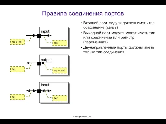
- 10. Verilog tutorial ( ) Правила соединения портов Входной порт модуля должен иметь тип соединение (связь) Выходной
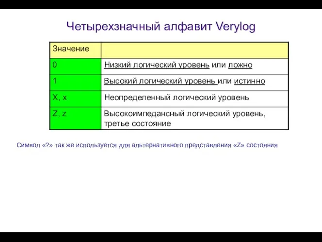
- 11. Четырехзначный алфавит Verylog Символ «?» так же используется для альтернативного представления «Z» состояния
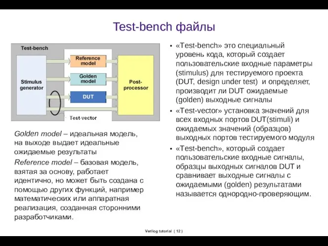
- 12. Verilog tutorial ( ) Test-bench файлы «Тest-bench» это специальный уровень кода, который создает пользовательские входные параметры
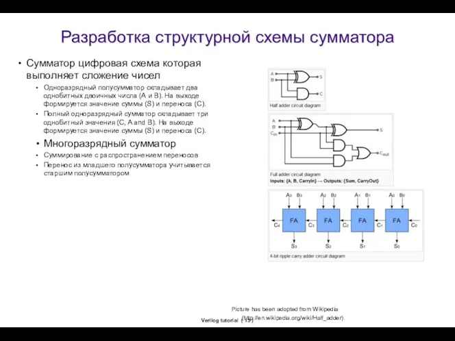
- 13. Verilog tutorial ( ) Разработка структурной схемы сумматора Сумматор цифровая схема которая выполняет сложение чисел Одноразрядный
- 14. Структура директории adder design sim syn sim.gate Папка с исходными кодами проекта Папка с результатами симуляции
- 15. Проект “adder” - сумматор Содержимое папки ‘design’ top.v full_adder.v half_adder_gate.v half_adder_rtl.v stimulus.v full_adder_ref.v checker.v
- 16. full_adder reset clk cin in1 in2 sum cout A B S C half_adder module half_adder (S,
- 17. Verilog tutorial ( ) Модуль full_adder (1/3) module full_adder(sum,cout,in1,in2,cin,clk,resetb); output sum, cout; /выходные сигналы input in1,
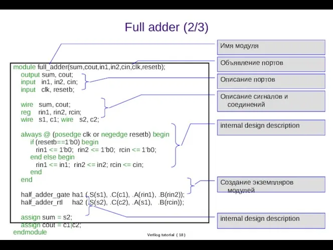
- 18. Verilog tutorial ( ) Full adder (2/3) module full_adder(sum,cout,in1,in2,cin,clk,resetb); output sum, cout; input in1, in2, cin;
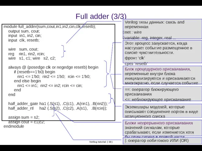
- 19. Verilog tutorial ( ) Full adder (3/3) module full_adder(sum,cout,in1,in2,cin,clk,resetb); output sum, cout; input in1, in2, cin;
- 20. Структурная модель полусумматора (gate level) module half_adder_gate (S, C, A, B); output S, C; input A,
- 21. Поведенческое описание объектов Полусумматор. Процессная форма описания поведения (Behavior model) module half_adder_beh1 (S, C, A, B);
- 22. Поведенческое описание объектов Полусумматор. Потоковое описание архитектуры (Data-flow model (RTL-модель)) (RTL, Register Transfer Level, Уровень регистровых
- 23. Модели мультиплексора (Behavior model) always @ (sel or a or b or c or d) if
- 24. Test-bench: stimulus module stimulus(out1,out2,out3,clk,resetb); output out1,out2,out3; input clk,resetb; reg out1,out2,out3; initial begin out1 / ожидание сброса
- 25. Verilog tutorial ( ) Test-bench: full_adder_ref module full_adder_ref(sum,cout,in1,in2,cin,clk,resetb); output sum, cout; input in1, in2, cin; input
- 26. Verilog tutorial ( ) Test-bench: checker module checker(in1,in2,cin,sum,cout,sumr,coutr,clk,resetb); input in1,in2,cin,sum,cout,sumr,coutr,clk,resetb; always @ (clk) begin if ({cout,sum}=={coutr,sumr})
- 27. Verilog tutorial ( ) Test-bench: top module top; wire in1, in2, cin; wire sum, cout, sumr,
- 28. Verilog tutorial ( ) Contents Design flow overview Hello world GUI based Command based Module Declaration
- 29. Verilog tutorial ( ) Contents Adder example What is adder Directory structure Example design Simulation Synthesis
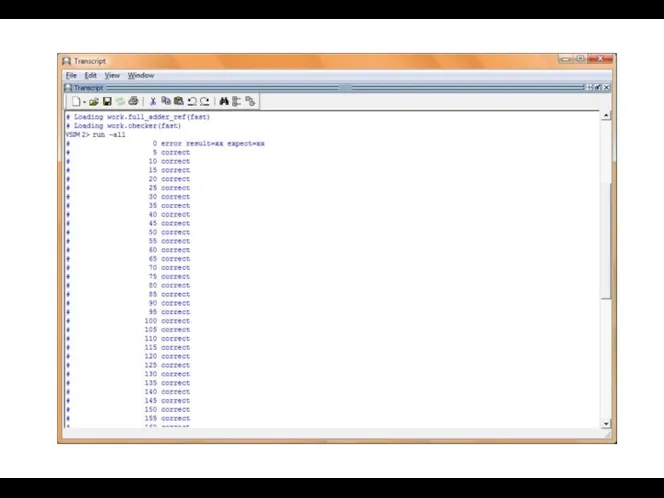
- 30. Результаты моделирования
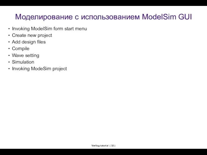
- 32. Verilog tutorial ( ) Моделирование с использованием ModelSim GUI Invoking ModelSim form start menu Create new
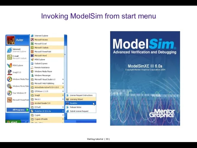
- 33. Verilog tutorial ( ) Invoking ModelSim from start menu
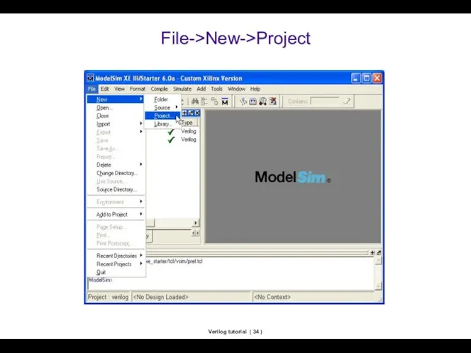
- 34. Verilog tutorial ( ) File->New->Project
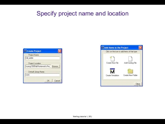
- 35. Verilog tutorial ( ) Specify project name and location
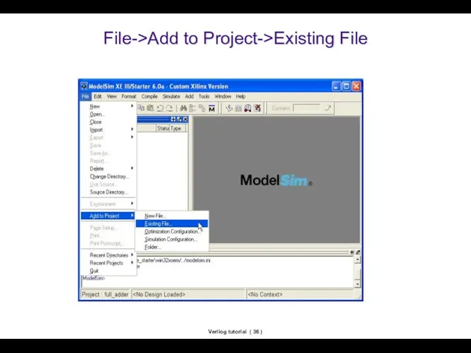
- 36. Verilog tutorial ( ) File->Add to Project->Existing File
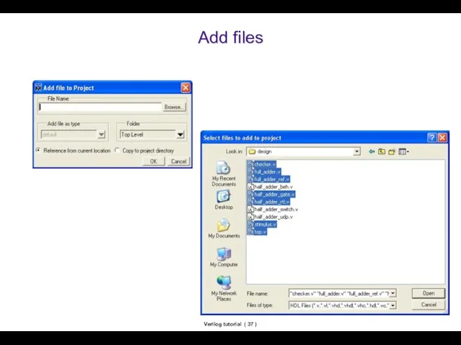
- 37. Verilog tutorial ( ) Add files
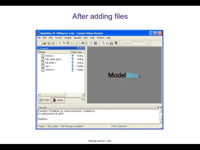
- 38. Verilog tutorial ( ) After adding files
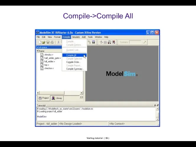
- 39. Verilog tutorial ( ) Compile->Compile All
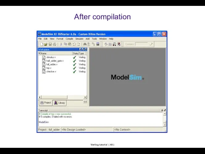
- 40. Verilog tutorial ( ) After compilation
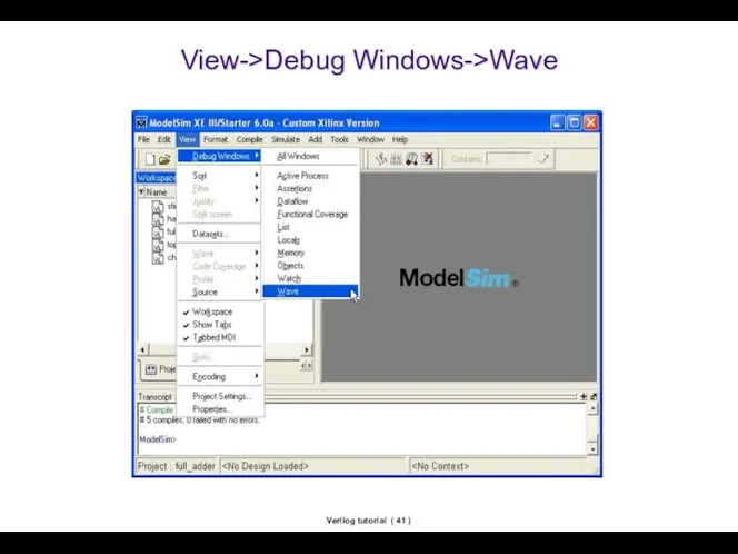
- 41. Verilog tutorial ( ) View->Debug Windows->Wave
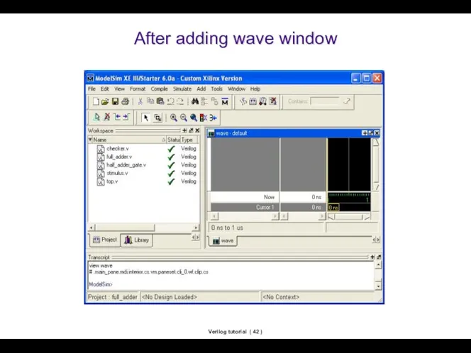
- 42. Verilog tutorial ( ) After adding wave window
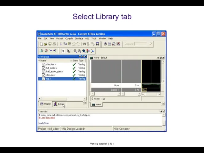
- 43. Verilog tutorial ( ) Select Library tab
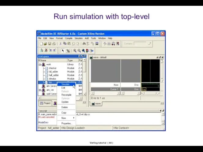
- 44. Verilog tutorial ( ) Run simulation with top-level
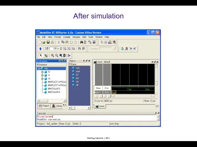
- 45. Verilog tutorial ( ) After simulation
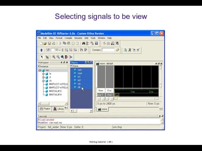
- 46. Verilog tutorial ( ) Selecting signals to be view
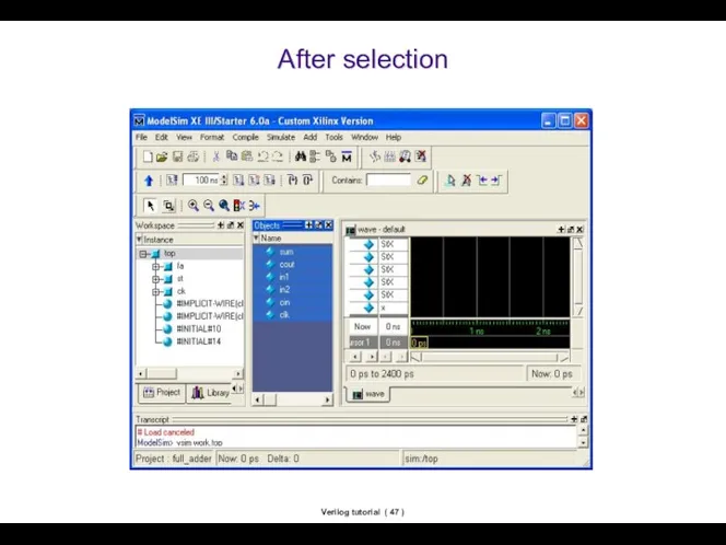
- 47. Verilog tutorial ( ) After selection
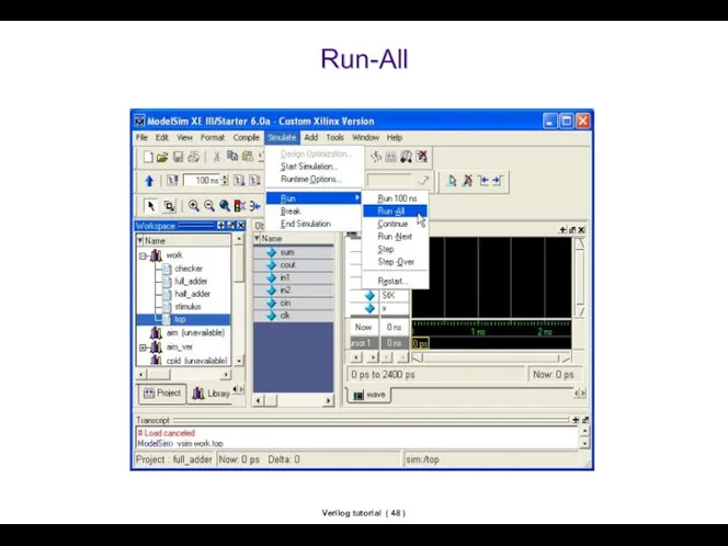
- 48. Verilog tutorial ( ) Run-All
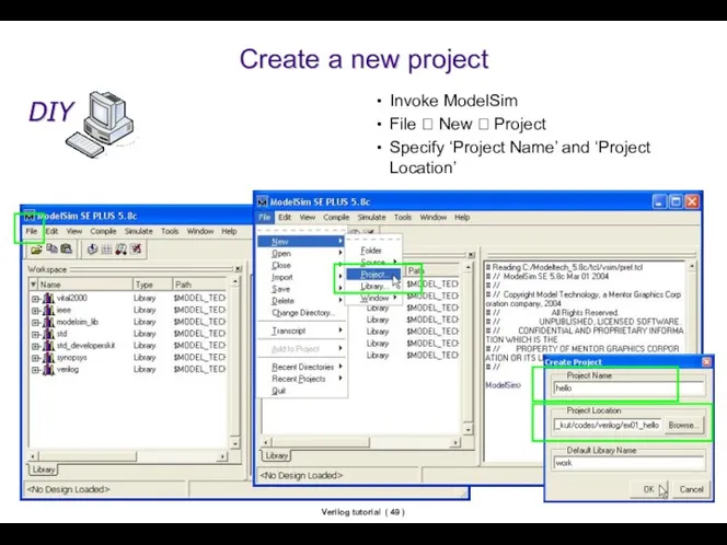
- 49. Verilog tutorial ( ) Create a new project Invoke ModelSim File ? New ? Project Specify
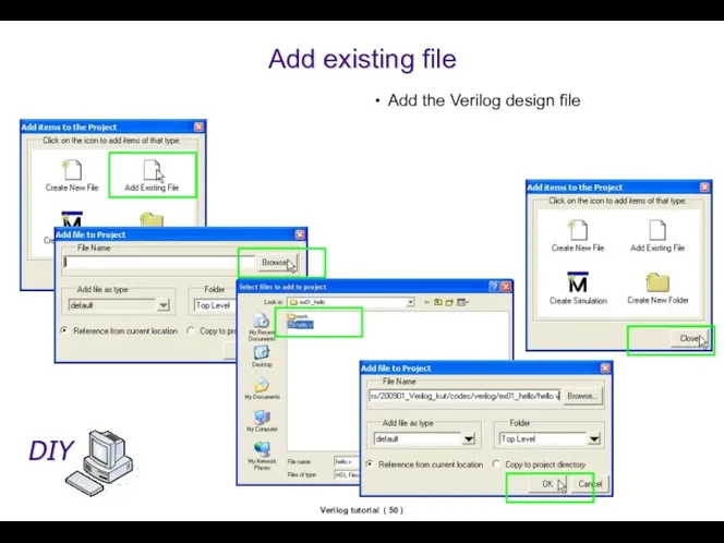
- 50. Verilog tutorial ( ) Add existing file Add the Verilog design file
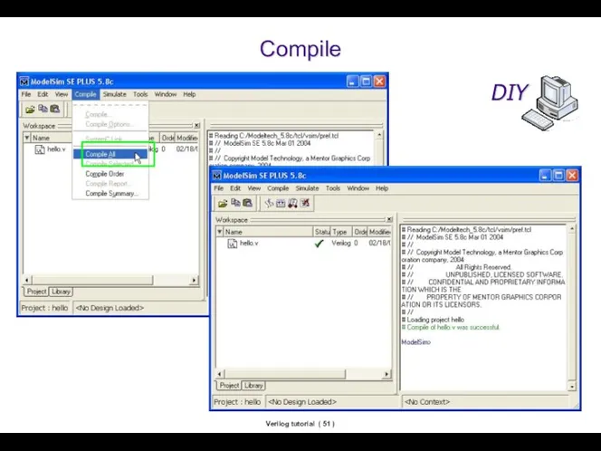
- 51. Verilog tutorial ( ) Compile
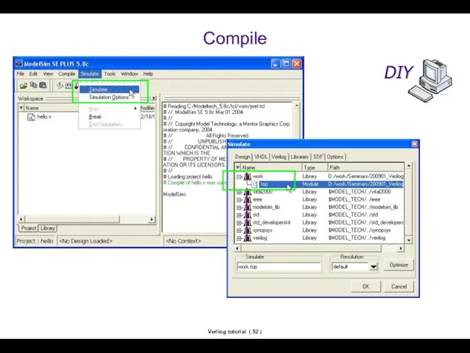
- 52. Verilog tutorial ( ) Compile
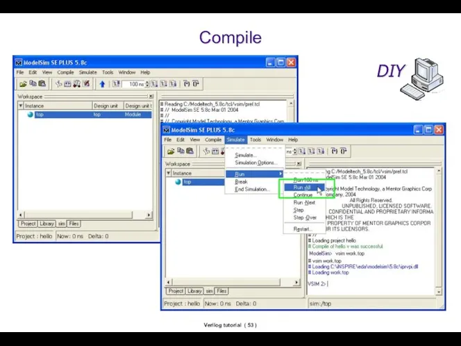
- 53. Verilog tutorial ( ) Compile
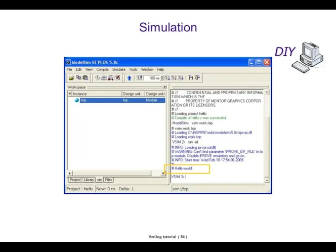
- 54. Verilog tutorial ( ) Simulation
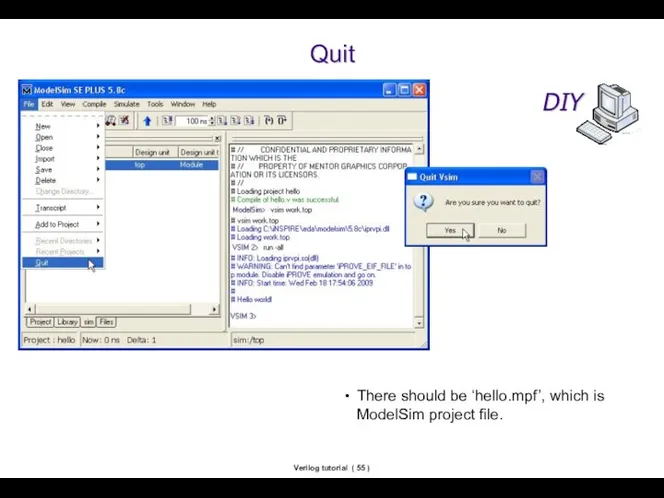
- 55. Verilog tutorial ( ) Quit There should be ‘hello.mpf’, which is ModelSim project file.
- 57. Скачать презентацию
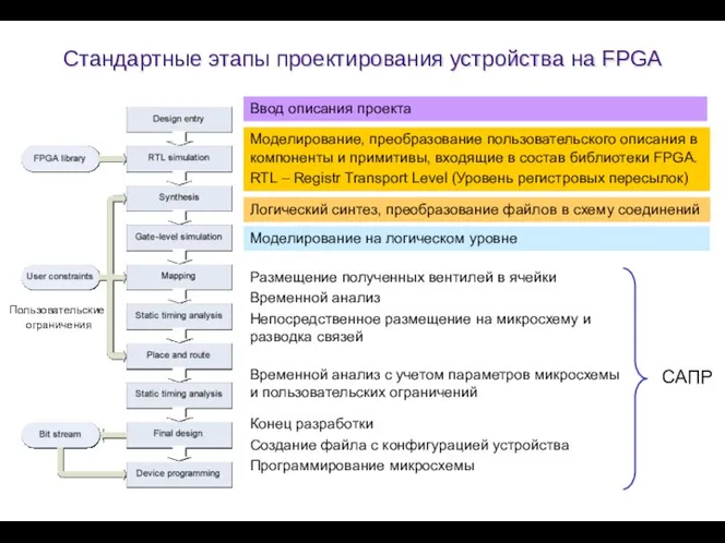
Стандартные этапы проектирования устройства на FPGA
Ввод описания проекта
Моделирование, преобразование
Стандартные этапы проектирования устройства на FPGA
Ввод описания проекта
Моделирование, преобразование
Verilog tutorial ( )
Contents
Етапы проектирования
Модули
Объявление
Создание экземпляров
Подключение портов
Test-bench файлы
Adder (разработка сумматора)
Проектирование
RTL
Verilog tutorial ( )
Contents
Етапы проектирования
Модули
Объявление
Создание экземпляров
Подключение портов
Test-bench файлы
Adder (разработка сумматора)
Проектирование
RTL
Verilog tutorial ( )
Объявление модуля
Модуль – базовая единица проекта.
Модуль должен быть
Verilog tutorial ( )
Объявление модуля
Модуль – базовая единица проекта.
Модуль должен быть
Verilog tutorial ( )
Создание экземпляра модуля
module ModG (AA, BB, CC);
input
Verilog tutorial ( )
Создание экземпляра модуля
module ModG (AA, BB, CC);
input
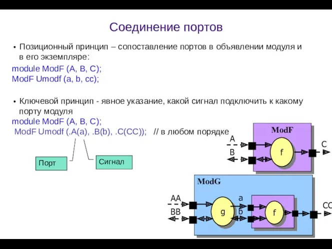
Соединение портов
Позиционный принцип – сопоставление портов в объявлении модуля и в
Соединение портов
Позиционный принцип – сопоставление портов в объявлении модуля и в
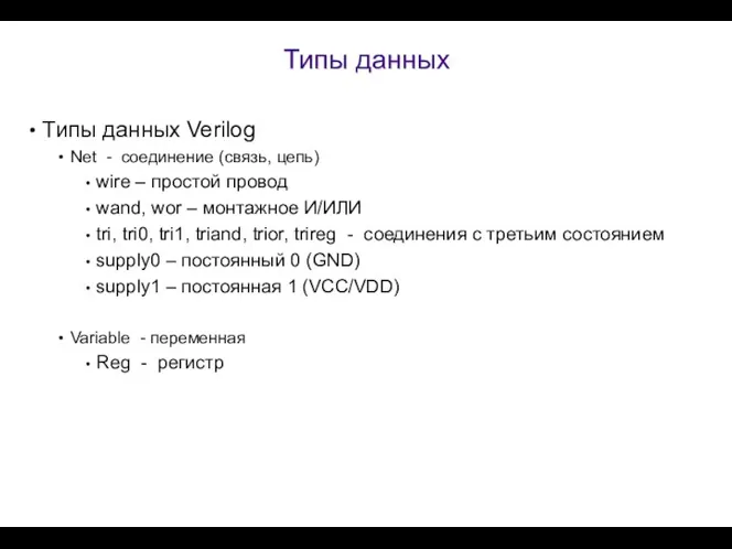
Типы данных
Типы данных Verilog
Net - соединение (связь, цепь)
wire – простой
Типы данных
Типы данных Verilog
Net - соединение (связь, цепь)
wire – простой
Introduction to Verilog Basic ( )
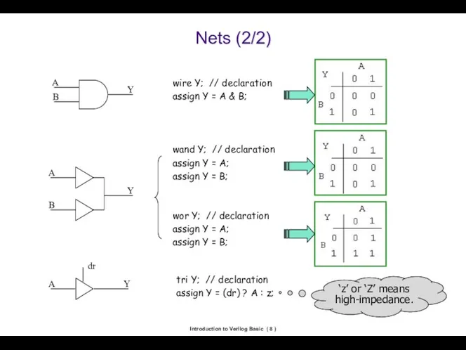
Nets (2/2)
wire Y; // declaration
assign Y
Introduction to Verilog Basic ( )
Nets (2/2)
wire Y; // declaration
assign Y
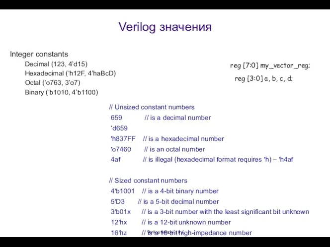
Verilog значения
Verilog tutorial ( )
Integer constants
Decimal (123, 4’d15)
Hexadecimal (‘h12F, 4’haBcD)
Octal (‘o763,
Verilog значения
Verilog tutorial ( )
Integer constants
Decimal (123, 4’d15)
Hexadecimal (‘h12F, 4’haBcD)
Octal (‘o763,
Verilog tutorial ( )
Правила соединения портов
Входной порт модуля должен иметь тип
Verilog tutorial ( )
Правила соединения портов
Входной порт модуля должен иметь тип
Четырехзначный алфавит Verylog
Символ «?» так же используется для альтернативного представления «Z»
Четырехзначный алфавит Verylog
Символ «?» так же используется для альтернативного представления «Z»
Verilog tutorial ( )
Test-bench файлы
«Тest-bench» это специальный уровень кода, который создает
Verilog tutorial ( )
Test-bench файлы
«Тest-bench» это специальный уровень кода, который создает
Verilog tutorial ( )
Разработка структурной схемы сумматора
Сумматор цифровая схема которая выполняет
Verilog tutorial ( )
Разработка структурной схемы сумматора
Сумматор цифровая схема которая выполняет
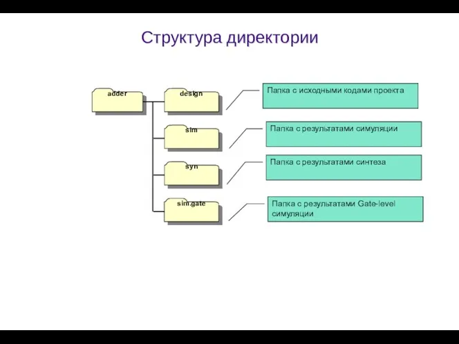
Структура директории
adder
design
sim
syn
sim.gate
Папка с исходными кодами проекта
Папка с результатами симуляции
Папка
Структура директории
adder
design
sim
syn
sim.gate
Папка с исходными кодами проекта
Папка с результатами симуляции
Папка
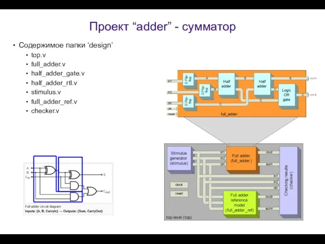
Проект “adder” - сумматор
Содержимое папки ‘design’
top.v
full_adder.v
half_adder_gate.v
half_adder_rtl.v
stimulus.v
full_adder_ref.v
checker.v
Проект “adder” - сумматор
Содержимое папки ‘design’
top.v
full_adder.v
half_adder_gate.v
half_adder_rtl.v
stimulus.v
full_adder_ref.v
checker.v
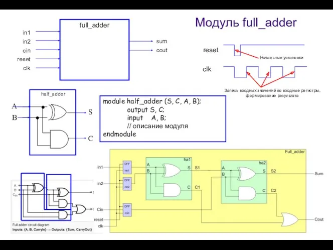
full_adder
reset
clk
cin
in1
in2
sum
cout
A
B
S
C
half_adder
module half_adder (S, C, A, B);
output S, C;
input A,
full_adder
reset
clk
cin
in1
in2
sum
cout
A
B
S
C
half_adder
module half_adder (S, C, A, B);
output S, C;
input A,
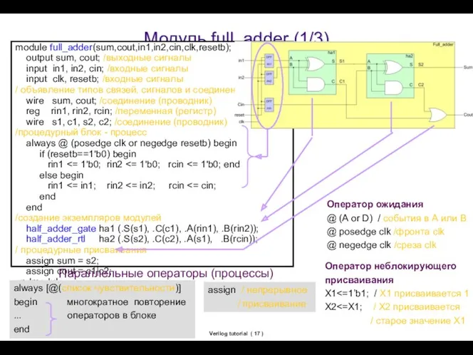
Verilog tutorial ( )
Модуль full_adder (1/3)
module full_adder(sum,cout,in1,in2,cin,clk,resetb);
output sum, cout; /выходные
Verilog tutorial ( )
Модуль full_adder (1/3)
module full_adder(sum,cout,in1,in2,cin,clk,resetb);
output sum, cout; /выходные
Verilog tutorial ( )
Full adder (2/3)
module full_adder(sum,cout,in1,in2,cin,clk,resetb);
output sum, cout;
input
Verilog tutorial ( )
Full adder (2/3)
module full_adder(sum,cout,in1,in2,cin,clk,resetb);
output sum, cout;
input
Verilog tutorial ( )
Full adder (3/3)
module full_adder(sum,cout,in1,in2,cin,clk,resetb);
output sum, cout;
input
Verilog tutorial ( )
Full adder (3/3)
module full_adder(sum,cout,in1,in2,cin,clk,resetb);
output sum, cout;
input
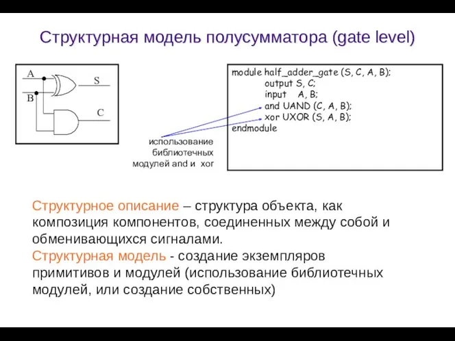
Структурная модель полусумматора (gate level)
module half_adder_gate (S, C, A, B);
output
Структурная модель полусумматора (gate level)
module half_adder_gate (S, C, A, B);
output
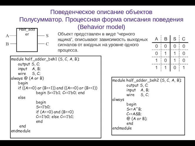
Поведенческое описание объектов
Полусумматор. Процессная форма описания поведения (Behavior model)
module half_adder_beh1
Поведенческое описание объектов
Полусумматор. Процессная форма описания поведения (Behavior model)
module half_adder_beh1
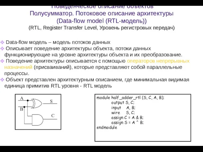
Поведенческое описание объектов
Полусумматор. Потоковое описание архитектуры
(Data-flow model (RTL-модель))
(RTL,
Поведенческое описание объектов Полусумматор. Потоковое описание архитектуры (Data-flow model (RTL-модель)) (RTL,
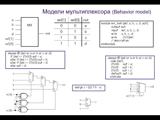
Модели мультиплексора (Behavior model)
always @ (sel or a or
Модели мультиплексора (Behavior model)
always @ (sel or a or
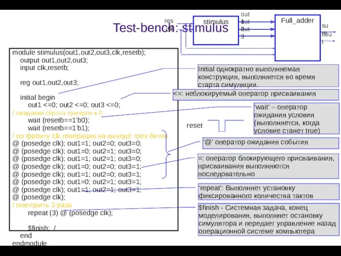
Test-bench: stimulus
module stimulus(out1,out2,out3,clk,resetb);
output out1,out2,out3;
input clk,resetb;
reg out1,out2,out3;
initial begin
Test-bench: stimulus
module stimulus(out1,out2,out3,clk,resetb);
output out1,out2,out3;
input clk,resetb;
reg out1,out2,out3;
initial begin
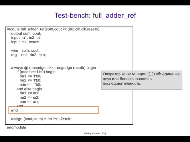
Verilog tutorial ( )
Test-bench: full_adder_ref
module full_adder_ref(sum,cout,in1,in2,cin,clk,resetb);
output sum, cout;
input in1,
Verilog tutorial ( )
Test-bench: full_adder_ref
module full_adder_ref(sum,cout,in1,in2,cin,clk,resetb);
output sum, cout;
input in1,
Verilog tutorial ( )
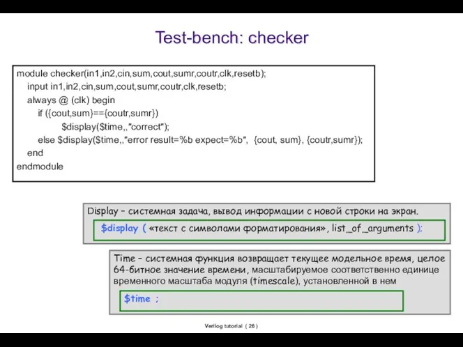
Test-bench: checker
module checker(in1,in2,cin,sum,cout,sumr,coutr,clk,resetb);
input in1,in2,cin,sum,cout,sumr,coutr,clk,resetb;
always @ (clk)
Verilog tutorial ( )
Test-bench: checker
module checker(in1,in2,cin,sum,cout,sumr,coutr,clk,resetb);
input in1,in2,cin,sum,cout,sumr,coutr,clk,resetb;
always @ (clk)
Verilog tutorial ( )
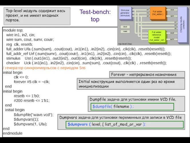
Test-bench:
top
module top;
wire in1, in2, cin;
wire
Verilog tutorial ( )
Test-bench:
top
module top;
wire in1, in2, cin;
wire
Verilog tutorial ( )
Contents
Design flow overview
Hello world
GUI based
Command based
Module
Declaration
Instantiation
Port
Test-bench
Adder example
What is
Verilog tutorial ( )
Contents
Design flow overview
Hello world
GUI based
Command based
Module
Declaration
Instantiation
Port
Test-bench
Adder example
What is
Verilog tutorial ( )
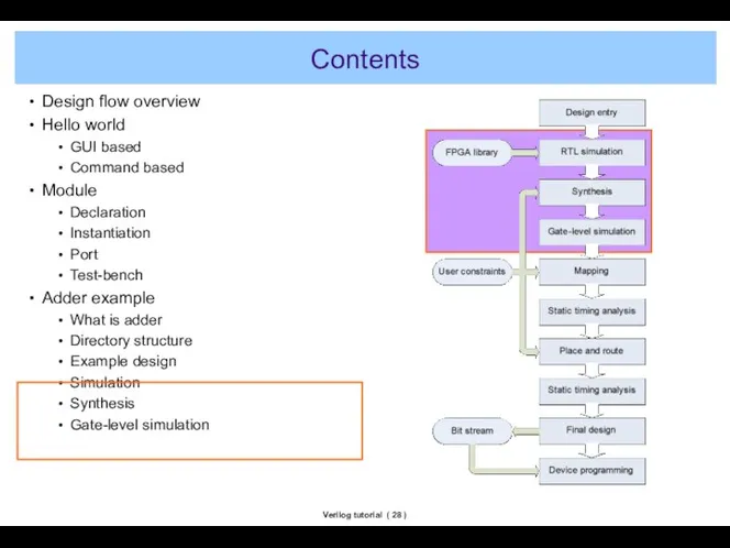
Contents
Adder example
What is adder
Directory structure
Example design
Simulation
Synthesis
Gate-level simulation
Map &
Verilog tutorial ( )
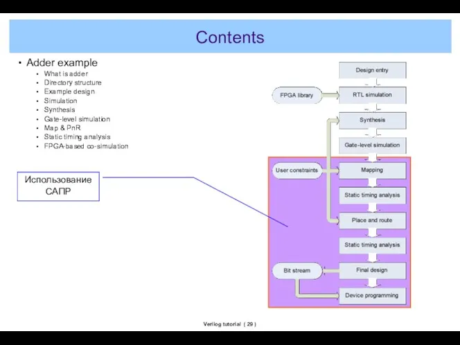
Contents
Adder example
What is adder
Directory structure
Example design
Simulation
Synthesis
Gate-level simulation
Map &
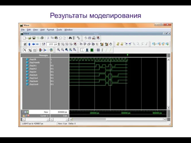
Результаты моделирования
Результаты моделирования
Verilog tutorial ( )
Моделирование с использованием ModelSim GUI
Invoking ModelSim form start
Verilog tutorial ( )
Моделирование с использованием ModelSim GUI
Invoking ModelSim form start
Verilog tutorial ( )
Invoking ModelSim from start menu
Verilog tutorial ( )
Invoking ModelSim from start menu
Verilog tutorial ( )
File->New->Project
Verilog tutorial ( )
File->New->Project
Verilog tutorial ( )
Specify project name and location
Verilog tutorial ( )
Specify project name and location
Verilog tutorial ( )
File->Add to Project->Existing File
Verilog tutorial ( )
File->Add to Project->Existing File
Verilog tutorial ( )
Add files
Verilog tutorial ( )
Add files
Verilog tutorial ( )
After adding files
Verilog tutorial ( )
After adding files
Verilog tutorial ( )
Compile->Compile All
Verilog tutorial ( )
Compile->Compile All
Verilog tutorial ( )
After compilation
Verilog tutorial ( )
After compilation
Verilog tutorial ( )
View->Debug Windows->Wave
Verilog tutorial ( )
View->Debug Windows->Wave
Verilog tutorial ( )
After adding wave window
Verilog tutorial ( )
After adding wave window
Verilog tutorial ( )
Select Library tab
Verilog tutorial ( )
Select Library tab
Verilog tutorial ( )
Run simulation with top-level
Verilog tutorial ( )
Run simulation with top-level
Verilog tutorial ( )
After simulation
Verilog tutorial ( )
After simulation
Verilog tutorial ( )
Selecting signals to be view
Verilog tutorial ( )
Selecting signals to be view
Verilog tutorial ( )
After selection
Verilog tutorial ( )
After selection
Verilog tutorial ( )
Run-All
Verilog tutorial ( )
Run-All
Verilog tutorial ( )
Create a new project
Invoke ModelSim
File ? New ?
Verilog tutorial ( )
Create a new project
Invoke ModelSim
File ? New ?
Verilog tutorial ( )
Add existing file
Add the Verilog design file
Verilog tutorial ( )
Add existing file
Add the Verilog design file
Verilog tutorial ( )
Compile
Verilog tutorial ( )
Compile
Verilog tutorial ( )
Compile
Verilog tutorial ( )
Compile
Verilog tutorial ( )
Compile
Verilog tutorial ( )
Compile
Verilog tutorial ( )
Simulation
Verilog tutorial ( )
Simulation
Verilog tutorial ( )
Quit
There should be ‘hello.mpf’, which is ModelSim project
Verilog tutorial ( )
Quit
There should be ‘hello.mpf’, which is ModelSim project
 Защита от несанкционированного доступа к информации
 ГОСТ Р ИСО/МЭК 12207. Основные процессы и взаимосвязь между документами в информационной системе согласно стандартам
 Основы сетевых технологий. Канальный уровень модели OSI. Часть 1. Лекция 5
 Двоичная системя счисления
 Вставка гиперссылки в веб-страницу
 Radio and Television today
 Архітектура, розроблення та експлуатація інформаційних систем корпоративного і національного рівнів
 Теория автоматов и формальных языков. Абстрактный синтез
 Формирование изображений на экране монитора
 Правило Если - то
 Логические основы компьютеров. Задания
 Безопасность программных средств
 Решение задач. Кодирование и операции над числами в разных системах счисления.
 Товарная политика библиотечно-информационных учреждений
 Электронная система здравохранения РК
 Робот-спасатель ЯМ-1
 Компьютерные цветовые модели
 Мысли как интерфейс мозга
 Бюллетень №1 новых поступлений
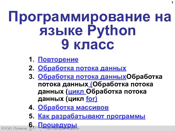 Программирование на языке Python. 9 класс
 Интеллектуальная система извлечения и анализа данных из текстов
 Основы программирования - Java. Знакомство с unit тестами. Списки – практика
 Методика решения заданий типа Робот в лабиринте
 Построение таблиц истинности для логических выражений
 Передавання інформації
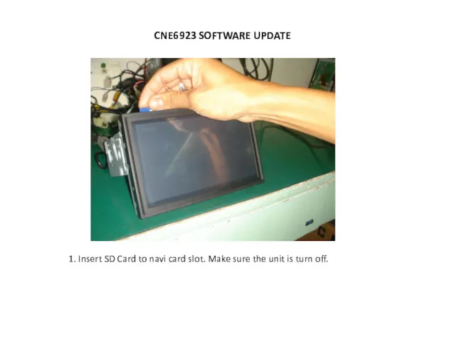 Cne6923 software update
 Техника безопасности во время каникул.
 МБУК Библиотека Моховского сельского поселения