- Center of vision correction ASTANA VISION

Содержание
- 2. Igor A Remesnikov, MD Optimization of TMR calculation for Topo-Guided LASIK Contoura Vision™ in astigmatic situations
- 3. Abbreviations AR – refraction measured with Auto-Ref-Keratometer SEQ – spheroequivalent of refraction TMR – topography-modified refraction
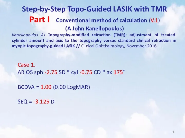
- 4. Step-by-Step Topo-Guided LASIK with TMR Part I Conventional method of calculation (V.1) (A John Kanellopoulos) Kanellopoulos
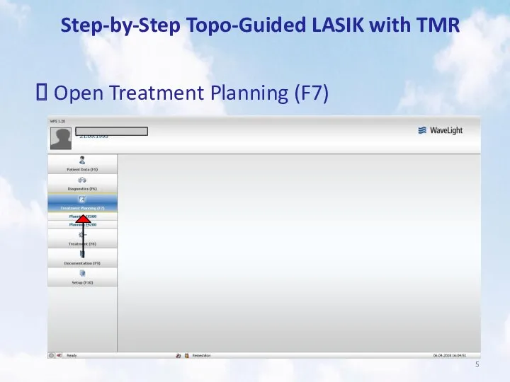
- 5. Step-by-Step Topo-Guided LASIK with TMR Open Treatment Planning (F7)
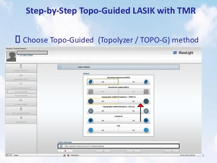
- 6. Step-by-Step Topo-Guided LASIK with TMR Choose Topo-Guided (Topolyzer / TOPO-G) method
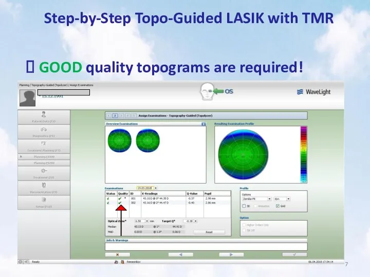
- 7. Step-by-Step Topo-Guided LASIK with TMR GOOD quality topograms are required!
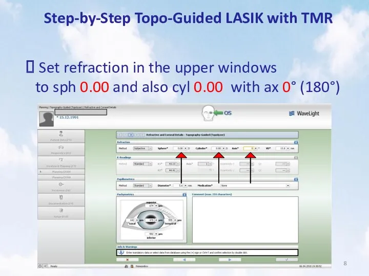
- 8. Step-by-Step Topo-Guided LASIK with TMR Set refraction in the upper windows to sph 0.00 and also
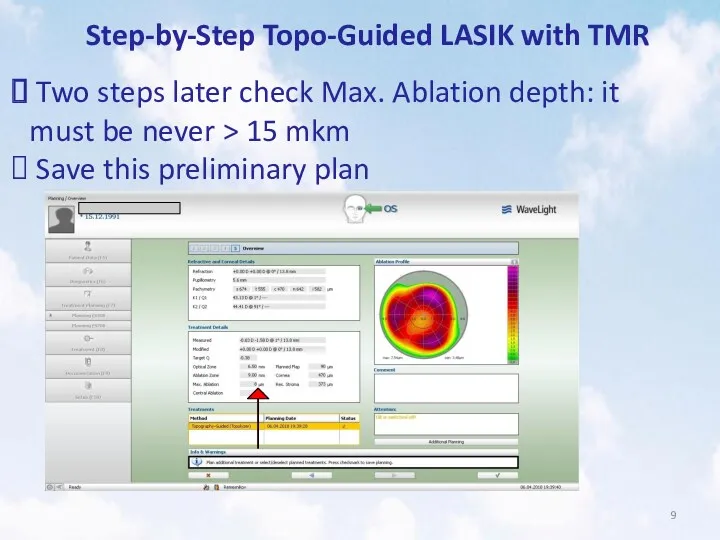
- 9. Step-by-Step Topo-Guided LASIK with TMR Two steps later check Max. Ablation depth: it must be never
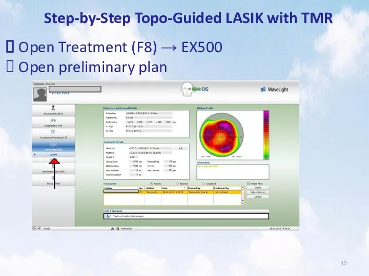
- 10. Step-by-Step Topo-Guided LASIK with TMR Open Treatment (F8) → EX500 Open preliminary plan
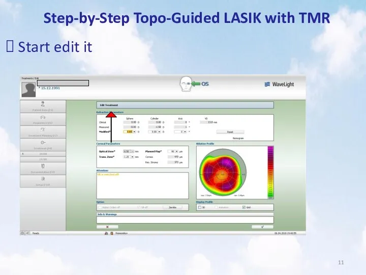
- 11. Step-by-Step Topo-Guided LASIK with TMR Start edit it
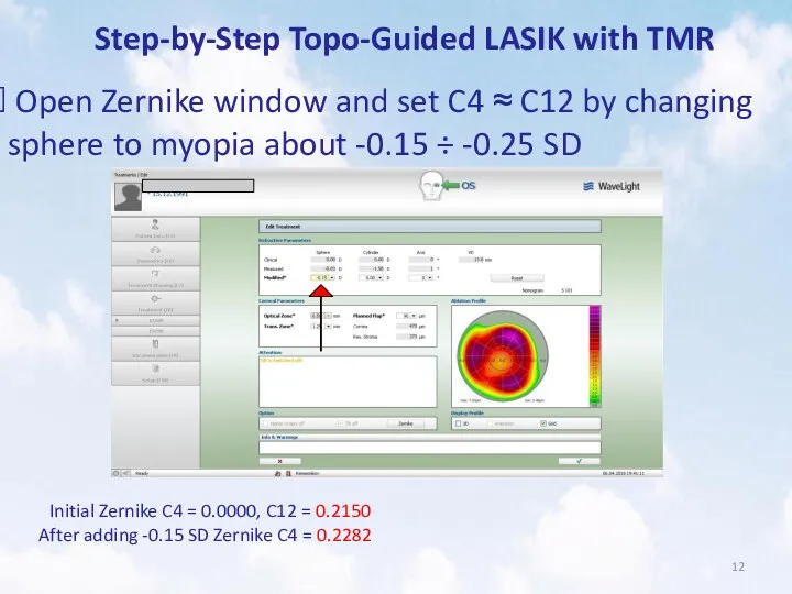
- 12. Step-by-Step Topo-Guided LASIK with TMR Open Zernike window and set C4 ≈ C12 by changing sphere
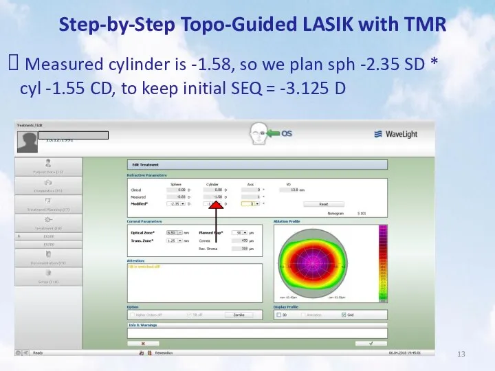
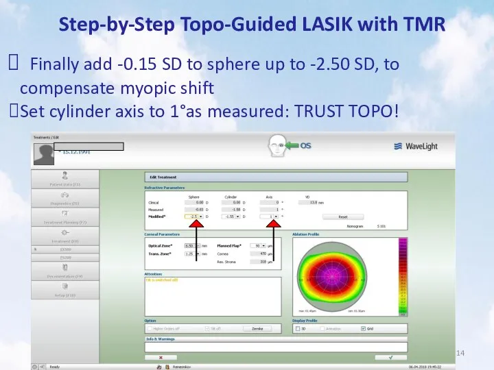
- 13. Step-by-Step Topo-Guided LASIK with TMR Measured cylinder is -1.58, so we plan sph -2.35 SD *
- 14. Step-by-Step Topo-Guided LASIK with TMR Finally add -0.15 SD to sphere up to -2.50 SD, to
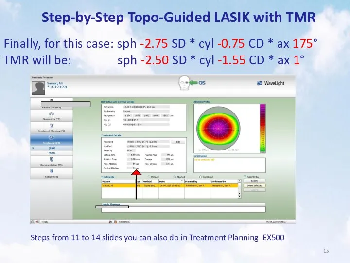
- 15. Step-by-Step Topo-Guided LASIK with TMR Finally, for this case: sph -2.75 SD * cyl -0.75 CD
- 16. Step-by-Step Topo-Guided LASIK with TMR But!!! If we have initially BCDVA = 1.00 (0.00 LogMAR) and
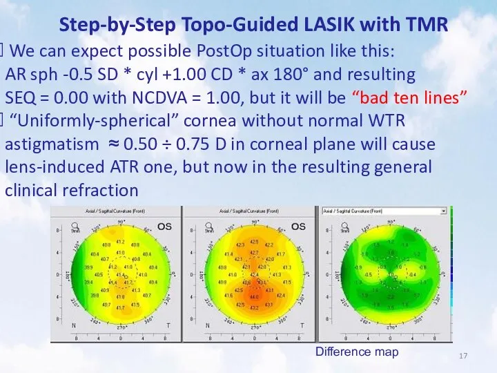
- 17. Step-by-Step Topo-Guided LASIK with TMR We can expect possible PostOp situation like this: AR sph -0.5
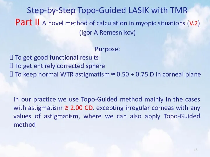
- 18. Step-by-Step Topo-Guided LASIK with TMR Part II A novel method of calculation in myopic situations (V.2)
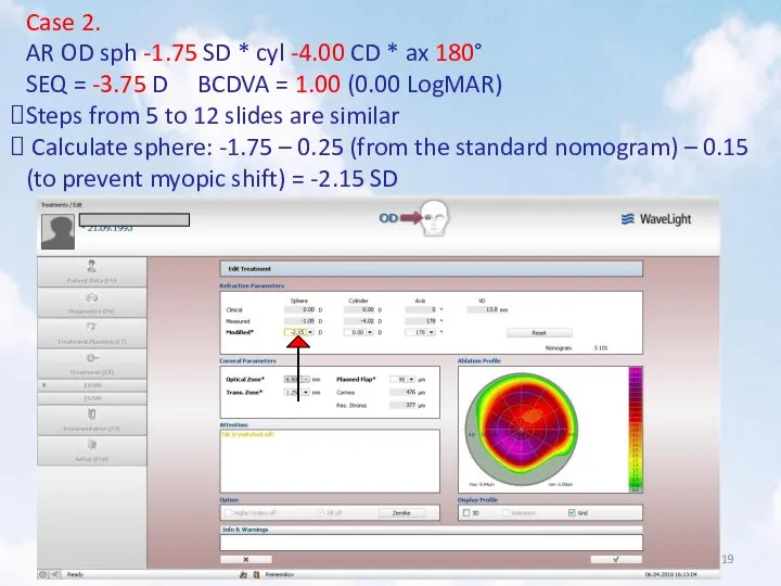
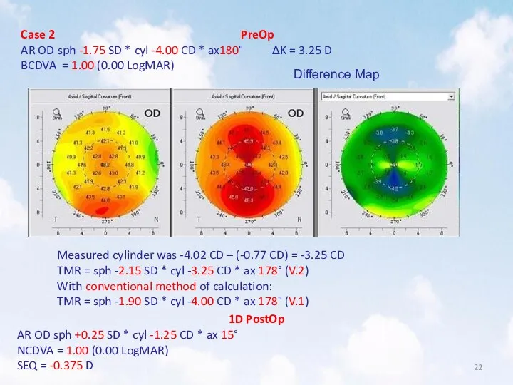
- 19. Case 2. AR OD sph -1.75 SD * cyl -4.00 CD * ax 180° SEQ =
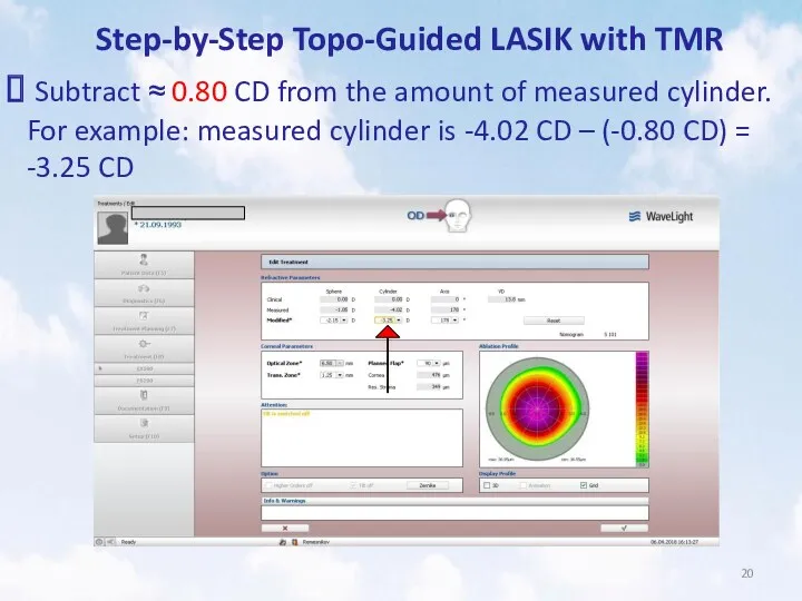
- 20. Step-by-Step Topo-Guided LASIK with TMR Subtract ≈ 0.80 CD from the amount of measured cylinder. For
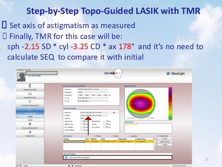
- 21. Step-by-Step Topo-Guided LASIK with TMR Set axis of astigmatism as measured Finally, TMR for this case
- 22. Case 2 PreOp AR OD sph -1.75 SD * cyl -4.00 CD * ax180° ΔK =
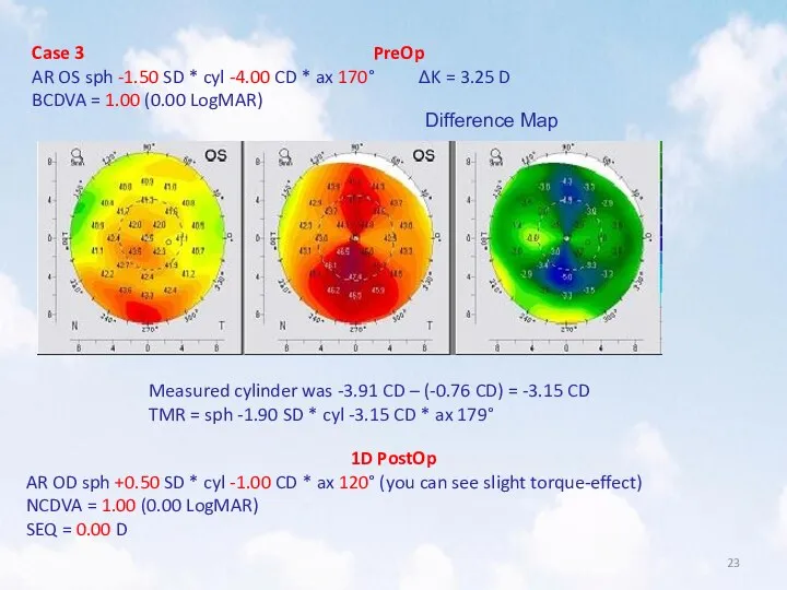
- 23. Case 3 PreOp AR OS sph -1.50 SD * cyl -4.00 CD * ax 170° ΔK
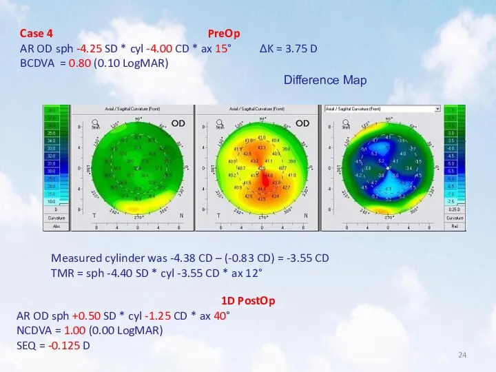
- 24. Case 4 PreOp AR OD sph -4.25 SD * cyl -4.00 CD * ax 15° ΔK
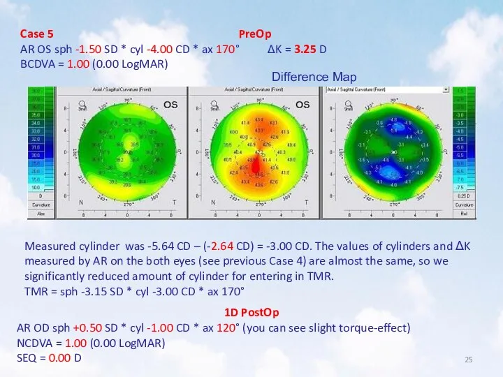
- 25. Case 5 PreOp AR OS sph -1.50 SD * cyl -4.00 CD * ax 170° ΔK
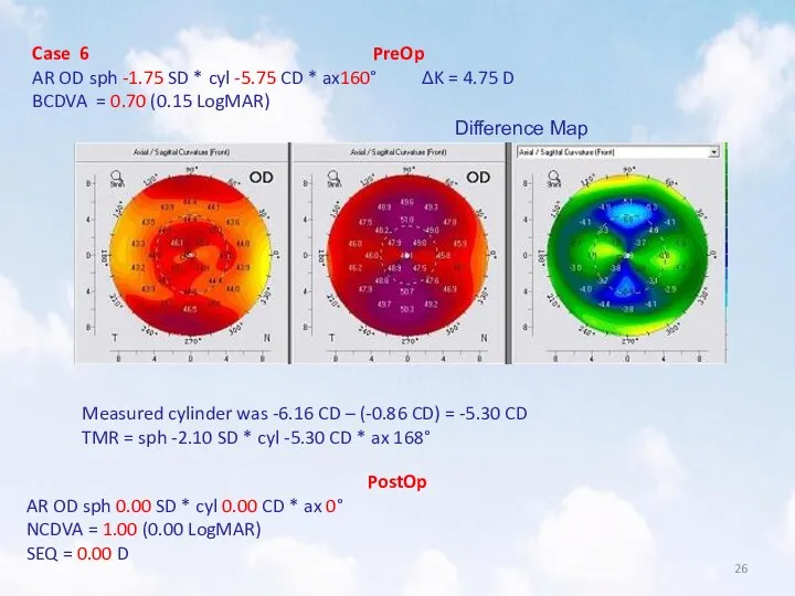
- 26. Case 6 PreOp AR OD sph -1.75 SD * cyl -5.75 CD * ax160° ΔK =
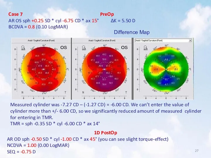
- 27. Case 7 PreOp AR OS sph +0.25 SD * cyl -6.75 CD * ax 15° ΔK
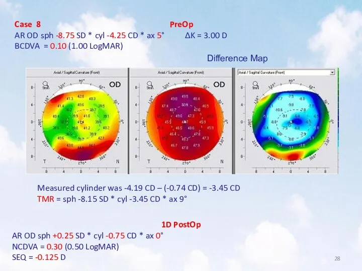
- 28. Case 8 PreOp AR OD sph -8.75 SD * cyl -4.25 CD * ax 5° ΔK
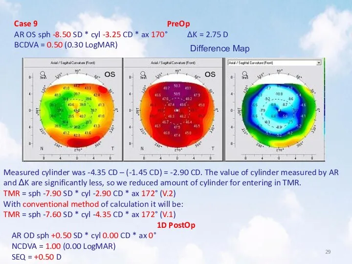
- 29. Case 9 PreOp AR OS sph -8.50 SD * cyl -3.25 CD * ax 170° ΔK
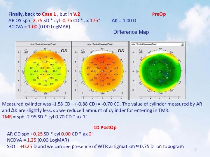
- 30. Finally, back to Case 1 , but in V.2 PreOp AR OS sph -2.75 SD *
- 31. Step-by-Step Topo-Guided LASIK with TMR Part III Calculation in mixed astigmatism situations Previously we successfully used
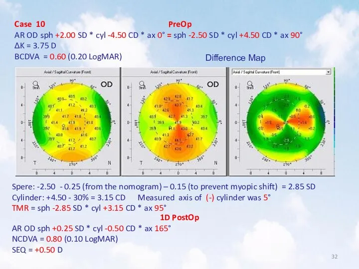
- 32. Case 10 PreOp AR OD sph +2.00 SD * cyl -4.50 CD * ax 0° =
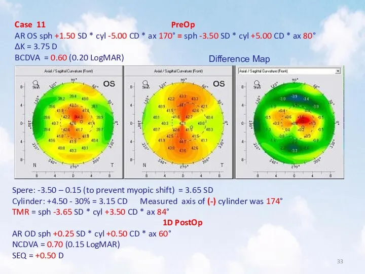
- 33. Case 11 PreOp AR OS sph +1.50 SD * cyl -5.00 CD * ax 170° =
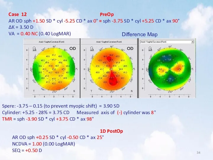
- 34. Case 12 PreOp AR OD sph +1.50 SD * cyl -5.25 CD * ax 0° =
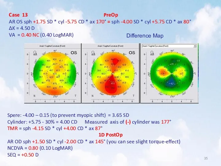
- 35. Case 13 PreOp AR OS sph +1.75 SD * cyl -5.75 CD * ax 170° =
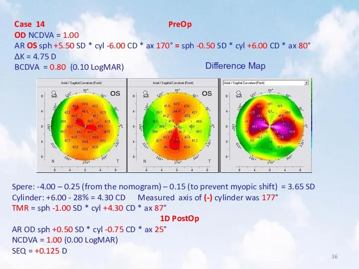
- 36. Case 14 PreOp OD NCDVA = 1.00 AR OS sph +5.50 SD * cyl -6.00 CD
- 37. NB! You can also put to use Custom Femto-flap in astigmatic cases. For example, for mixed
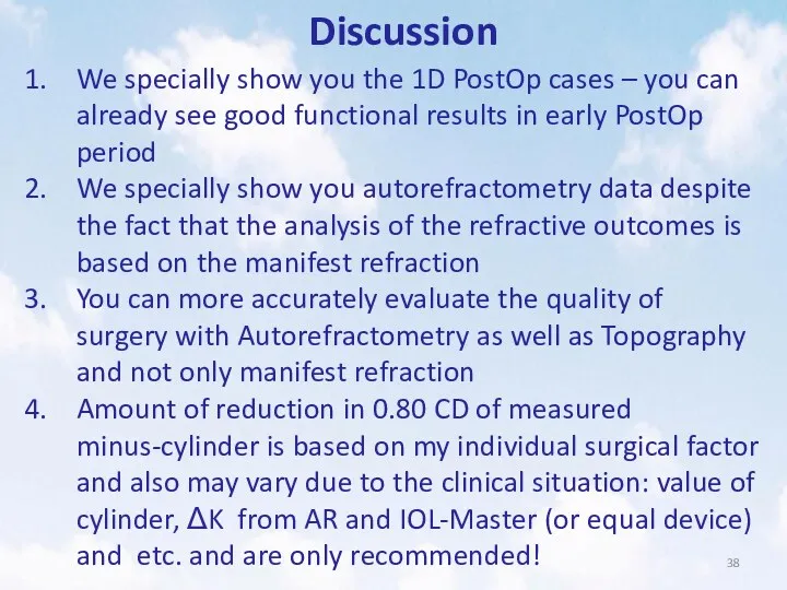
- 38. Discussion We specially show you the 1D PostOp cases – you can already see good functional
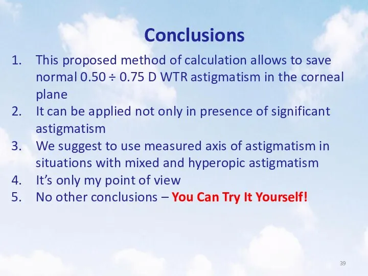
- 39. Conclusions This proposed method of calculation allows to save normal 0.50 ÷ 0.75 D WTR astigmatism
- 41. Скачать презентацию
Igor A Remesnikov, MD
Optimization of TMR calculation
for Topo-Guided LASIK Contoura Vision™
Igor A Remesnikov, MD
Optimization of TMR calculation
for Topo-Guided LASIK Contoura Vision™
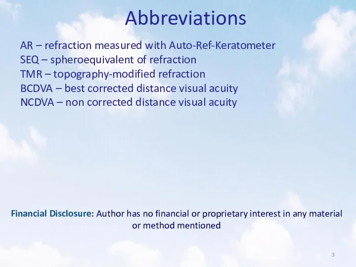
Abbreviations
AR – refraction measured with Auto-Ref-Keratometer
SEQ – spheroequivalent of refraction
TMR –
Abbreviations
AR – refraction measured with Auto-Ref-Keratometer
SEQ – spheroequivalent of refraction
TMR –
Step-by-Step Topo-Guided LASIK with TMR
Part I Conventional method of calculation
Step-by-Step Topo-Guided LASIK with TMR
Part I Conventional method of calculation
Step-by-Step Topo-Guided LASIK with TMR
Open Treatment Planning (F7)
Step-by-Step Topo-Guided LASIK with TMR
Open Treatment Planning (F7)
Step-by-Step Topo-Guided LASIK with TMR
Choose Topo-Guided (Topolyzer / TOPO-G)
Step-by-Step Topo-Guided LASIK with TMR
Choose Topo-Guided (Topolyzer / TOPO-G)
Step-by-Step Topo-Guided LASIK with TMR
GOOD quality topograms are required!
Step-by-Step Topo-Guided LASIK with TMR
GOOD quality topograms are required!
Step-by-Step Topo-Guided LASIK with TMR
Set refraction in the upper
Step-by-Step Topo-Guided LASIK with TMR
Set refraction in the upper
Step-by-Step Topo-Guided LASIK with TMR
Two steps later check Max.
Step-by-Step Topo-Guided LASIK with TMR
Two steps later check Max.
Step-by-Step Topo-Guided LASIK with TMR
Open Treatment (F8) → EX500
Step-by-Step Topo-Guided LASIK with TMR
Open Treatment (F8) → EX500
Step-by-Step Topo-Guided LASIK with TMR
Start edit it
Step-by-Step Topo-Guided LASIK with TMR
Start edit it
Step-by-Step Topo-Guided LASIK with TMR
Open Zernike window and set
Step-by-Step Topo-Guided LASIK with TMR
Open Zernike window and set
Step-by-Step Topo-Guided LASIK with TMR
Measured cylinder is -1.58, so
Step-by-Step Topo-Guided LASIK with TMR
Measured cylinder is -1.58, so
Step-by-Step Topo-Guided LASIK with TMR
Finally add -0.15 SD to
Step-by-Step Topo-Guided LASIK with TMR
Finally add -0.15 SD to
Step-by-Step Topo-Guided LASIK with TMR
Finally, for this case: sph -2.75
Step-by-Step Topo-Guided LASIK with TMR
Finally, for this case: sph -2.75
Step-by-Step Topo-Guided LASIK with TMR
But!!!
If we have initially BCDVA
Step-by-Step Topo-Guided LASIK with TMR
But!!!
If we have initially BCDVA
Step-by-Step Topo-Guided LASIK with TMR
We can expect possible PostOp
Step-by-Step Topo-Guided LASIK with TMR
We can expect possible PostOp
Step-by-Step Topo-Guided LASIK with TMR
Part II A novel method of
Step-by-Step Topo-Guided LASIK with TMR
Part II A novel method of
Case 2.
AR OD sph -1.75 SD * cyl -4.00 CD
Case 2.
AR OD sph -1.75 SD * cyl -4.00 CD
Step-by-Step Topo-Guided LASIK with TMR
Subtract ≈ 0.80 CD from
Step-by-Step Topo-Guided LASIK with TMR
Subtract ≈ 0.80 CD from
Step-by-Step Topo-Guided LASIK with TMR
Set axis of astigmatism as
Step-by-Step Topo-Guided LASIK with TMR
Set axis of astigmatism as
Case 2 PreOp
AR OD sph -1.75 SD * cyl -4.00
Case 2 PreOp
AR OD sph -1.75 SD * cyl -4.00
Case 3 PreOp
AR OS sph -1.50 SD * cyl -4.00
Case 3 PreOp
AR OS sph -1.50 SD * cyl -4.00
Case 4 PreOp
AR OD sph -4.25 SD * cyl -4.00
Case 4 PreOp
AR OD sph -4.25 SD * cyl -4.00
Case 5 PreOp
AR OS sph -1.50 SD * cyl -4.00
Case 5 PreOp
AR OS sph -1.50 SD * cyl -4.00
Case 6 PreOp
AR OD sph -1.75 SD * cyl -5.75
Case 6 PreOp
AR OD sph -1.75 SD * cyl -5.75
Case 7 PreOp
AR OS sph +0.25 SD * cyl -6.75
Case 7 PreOp
AR OS sph +0.25 SD * cyl -6.75
Case 8 PreOp
AR OD sph -8.75 SD * cyl -4.25
Case 8 PreOp
AR OD sph -8.75 SD * cyl -4.25
Case 9 PreOp
AR OS sph -8.50 SD * cyl -3.25
Case 9 PreOp
AR OS sph -8.50 SD * cyl -3.25
Finally, back to Case 1 , but in V.2 PreOp
AR
Finally, back to Case 1 , but in V.2 PreOp
AR
Step-by-Step Topo-Guided LASIK with TMR
Part III Calculation in mixed astigmatism
Step-by-Step Topo-Guided LASIK with TMR
Part III Calculation in mixed astigmatism
Case 10 PreOp
AR OD sph +2.00 SD * cyl -4.50
Case 10 PreOp
AR OD sph +2.00 SD * cyl -4.50
Case 11 PreOp
AR OS sph +1.50 SD * cyl -5.00
Case 11 PreOp
AR OS sph +1.50 SD * cyl -5.00
Case 12 PreOp
AR OD sph +1.50 SD * cyl -5.25
Case 12 PreOp
AR OD sph +1.50 SD * cyl -5.25
Case 13 PreOp
AR OS sph +1.75 SD * cyl -5.75
Case 13 PreOp
AR OS sph +1.75 SD * cyl -5.75
Case 14 PreOp
OD NCDVA = 1.00
AR OS sph +5.50 SD
Case 14 PreOp
OD NCDVA = 1.00
AR OS sph +5.50 SD
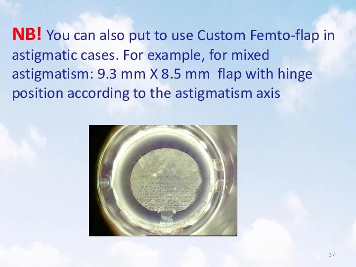
NB! You can also put to use Custom Femto-flap in astigmatic
NB! You can also put to use Custom Femto-flap in astigmatic
Discussion
We specially show you the 1D PostOp cases – you can
Discussion
We specially show you the 1D PostOp cases – you can
Conclusions
This proposed method of calculation allows to save normal 0.50 ÷
Conclusions
This proposed method of calculation allows to save normal 0.50 ÷
 Виды медицинской помощи
 Предлежание плаценты. Понятие, классификация, этиология и патогенез, клиническая картина, осложнения, лечение
 Өсіргіш заттар. Өсіргіш заттардың өсімдіктерге әсер ету механизмі. Ауксин әсері
 Острая ревматическая лихорадка у детей
 Хроническая сердечная недостаточность
 Нравственные начала в работе врача
 Профилактика и диагностика врожденной патологии плода
 Skalowanie w OIT. Systemy skalowania
 Мочекаменная болезнь. Почечная колика
 Методики рентгенологического исследования тонкой и толстой кишки
 КТ и МРТ в диагностике очаговых образований печени: что, когда, кому?
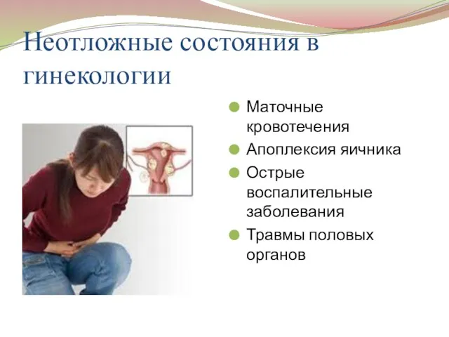 Неотложные состояния в гинекологии
 Заболевания конечностей и их лечение. Ортопедическая ковка
 Dental clinic
 ТЭЛА. Источники образования тромбоэмболов. Механизм смерти при тэла
 Экстрапирамдалық жүйе аурулары
 Биологически активные добавки (БАД)
 Иммунитет и проблемы питания жителей современного города
 Развитие плода. Влияние вредных факторов на плод. Критические периоды развития. Применение лекарственных препаратов в акушерстве
 Спадкові хвороби
 Здоровое питание
 Кожа и ее производные
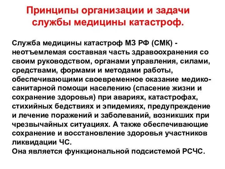 Принципы организации и задачи службы медицины катастроф
 Дифференциальная диагностика типичных образований печени
 Холодовая травма. Гипотермия
 Патология эндокринной системы
 Блокируемый интрамедуллярный остеосинтез (БИОС)
 Модель современной медицинской сестры