- Fuel system

Содержание
- 2. MAIN PARTS OF THE FUEL SYSTEM FUEL STORAGE PRESSURE REFUELING SYSTEM ENGINE FUEL FEED APU FUEL
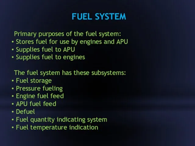
- 3. FUEL SYSTEM Primary purposes of the fuel system: Stores fuel for use by engines and APU
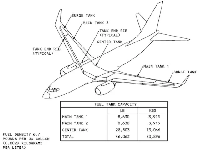
- 4. FUEL STORAGE These tanks store fuel: Main tank 1 Main tank 2 Center tank The main
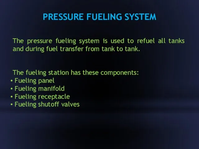
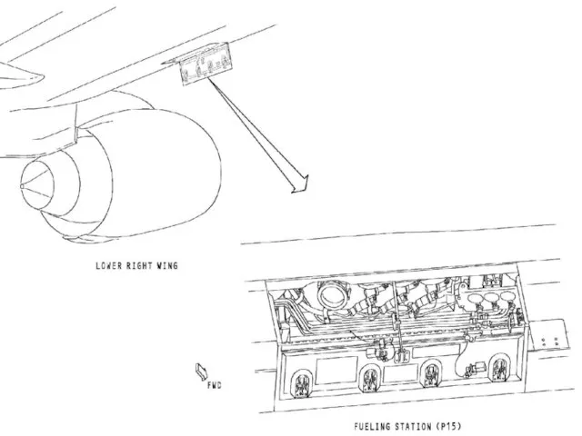
- 6. PRESSURE FUELING SYSTEM The pressure fueling system is used to refuel all tanks and during fuel
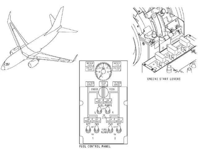
- 8. ENGINE FUEL FEED The engine fuel feed system supplies fuel from the fuel tanks to the
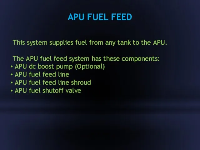
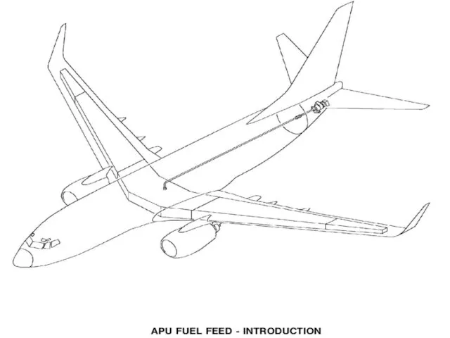
- 10. APU FUEL FEED This system supplies fuel from any tank to the APU. The APU fuel
- 12. The defuel system removes fuel from the fuel tanks to the refuel station. The defuel system
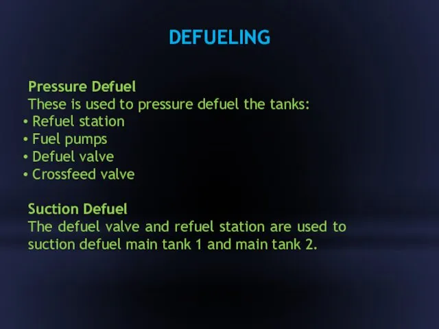
- 13. DEFUELING Pressure Defuel These is used to pressure defuel the tanks: Refuel station Fuel pumps Defuel
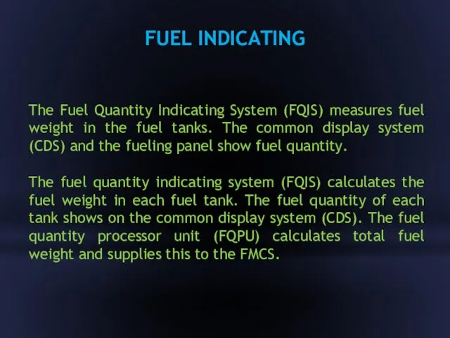
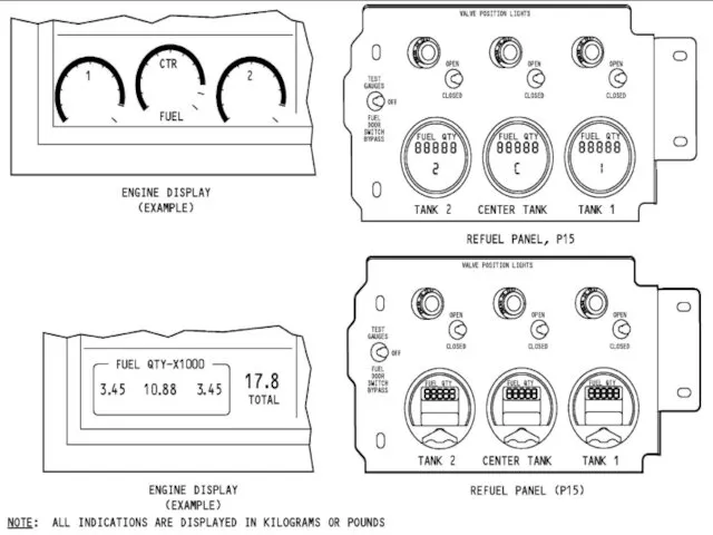
- 15. FUEL INDICATING The Fuel Quantity Indicating System (FQIS) measures fuel weight in the fuel tanks. The
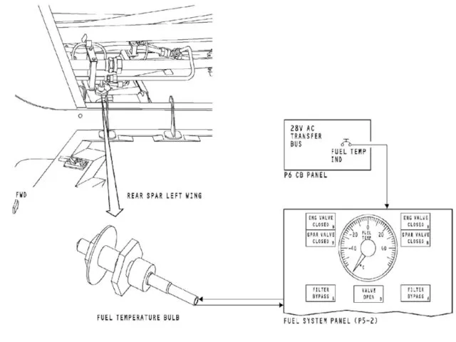
- 17. FUEL TEMPERATURE INDICATING SYSTEM Purpose The fuel temperature indicating system shows fuel temperature in main tank
- 18. Components The fuel temperature indicator is a resistance ratiometer instrument. The fuel temperature bulb is a
- 20. FUEL MEASURING STICK There are six measuring sticks in main tank 1 and main tank 2.
- 22. Скачать презентацию
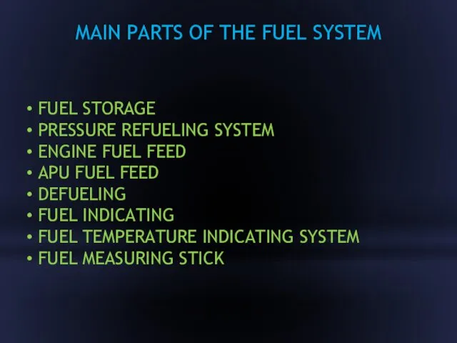
MAIN PARTS OF THE FUEL SYSTEM
FUEL STORAGE
PRESSURE REFUELING
MAIN PARTS OF THE FUEL SYSTEM
FUEL STORAGE
PRESSURE REFUELING
FUEL SYSTEM
Primary purposes of the fuel system:
Stores fuel for use
Primary purposes of the fuel system:
Stores fuel for use
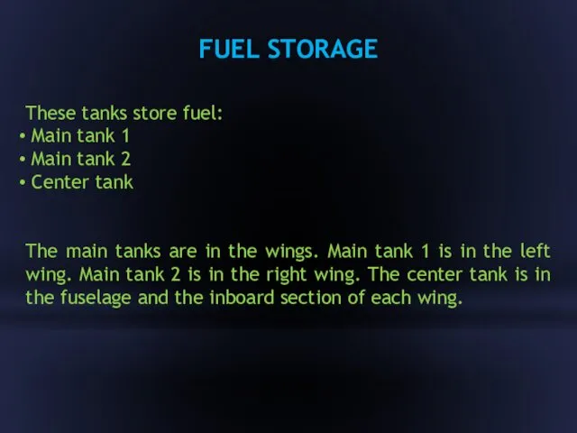
FUEL STORAGE
These tanks store fuel:
Main tank 1
Main
These tanks store fuel:
Main tank 1
Main
PRESSURE FUELING SYSTEM
The pressure fueling system is used to refuel all
The pressure fueling system is used to refuel all
ENGINE FUEL FEED
The engine fuel feed system supplies fuel from the
The engine fuel feed system supplies fuel from the
APU FUEL FEED
This system supplies fuel from any tank to the
This system supplies fuel from any tank to the
The defuel system removes fuel from the fuel tanks to the
DEFUELING
Pressure Defuel
These is used to pressure defuel the tanks:
Pressure Defuel
These is used to pressure defuel the tanks:

FUEL INDICATING
The Fuel Quantity Indicating System (FQIS) measures fuel weight
The Fuel Quantity Indicating System (FQIS) measures fuel weight
FUEL TEMPERATURE INDICATING SYSTEM
Purpose
The fuel temperature indicating system shows
Purpose
The fuel temperature indicating system shows
Components
The fuel temperature indicator is a resistance ratiometer instrument.
The
Components
The fuel temperature indicator is a resistance ratiometer instrument.
The
FUEL MEASURING STICK
There are six measuring sticks in main tank
There are six measuring sticks in main tank
 Презентация к уроку Спирты
 Балалардың жүйке іс әрекеттерінің дамуын бағалау
 Учимся готовить: десерт Клубничка
 Интеллектуальная система технического зрения для мониторинга состояния и содержания сельскохозяйственных животных
 Презентационные материалы к аттестации заместителя директора по воспитательной работе
 Презентация Молоко и молочные продукты
 Презентация Применение ПАВ
 Детёныши животных
 Архитектура параллельных вычислительных систем. Часть 1. История и проблематика. Основы параллельного программирования
 Сахарный диабет при беременности, в родах и послеродовом периоде
 Развивающее обучение
 Управление риском
 ФГОС дошкольного образования.
 Дербес компьютер. Компьютердің құрылысы
 Отчет по прохождению производственной практики
 Напряженность электростатического поля. Линии напряженности электростатического поля
 Кто хочет стать миллионером. Он-лайн игра
 Двигательная активность детей в группе
 Тез үдемелі гломерулонефрит
 Презентация Оптимизация образовательного процесса за счет интеграции разных видов деятельности
 Микропроцессорная система зажигания
 Вводные слова и предложения
 Элементарная трудовая деятельность и начальные формы учебной деятельности в дошкольном возрасте
 Тема: Здоровый образ жизни.
 Центр мониторинга социальных сетей
 Метаболизм липидов. Липолиз. Окисление жирных кислот и глицерола
 Ярославское высшее военное училище противовоздушной обороны
 Презентация по педагогическому познавательно-творческому проекту на тему: Осень золотая