- MAN Diesel PrimeServ Academy ME Concept

Содержание
- 2. Control system: - Multi Purpose Controller - Control Network - Main Operating Panel - Local Operating
- 3. Control Systems Bridge Ctr System Engine Ctr System
- 4. Engine Control System MPC & Control Network 2 redundant control networks are connecting all Multi Purpose
- 5. Multi Purpose Controller, MPC 24 VDC, isolated system, A is UPS 2 separate 16 A breakers
- 6. Multi Purpose Controller, MPC DIP Switches DIP Switches & Reset push button Power Plug
- 7. Multi Purpose Controller, MPC Amplifier for FIVA (CCU’s) and Hydraulic pumps (ACU’s) Multi Purpose Controller ’IP
- 8. Multi Purpose Controller LED Information Code The LED gives information, either as a constant light or
- 9. Multi Purpose Controller LED Information Code
- 10. Control Network 120 Ω 120 Ω 120 Ω 120 Ω
- 11. MPC’s Nordic Brasilia – 6S70ME-C
- 12. Engine Interface Control Unit, EICU Interface to External Systems
- 13. Engine Interface Control Unit, EICU Speed Setpoint Pre defined RPM for starting. Stop Gives the minimum
- 14. Engine Control Unit, ECU Start Block
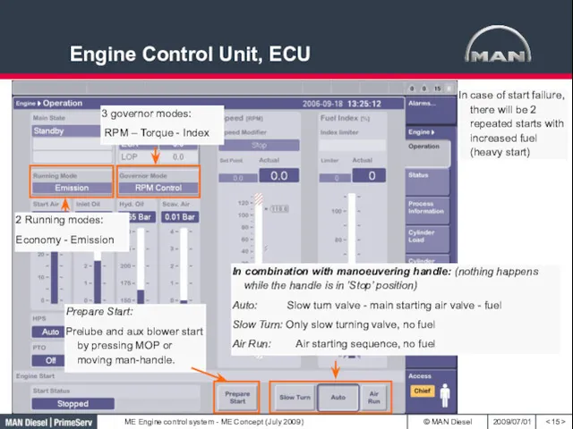
- 15. Engine Control Unit, ECU 3 governor modes: RPM – Torque - Index 2 Running modes: Economy
- 16. Engine Control Unit, ECU Injection Profiles
- 17. Engine Control Unit, ECU Governor Pre defined index for starting. Max fuel set by C/E, for
- 18. Cylinder Control Unit, CCU Fuel plunger position 4-20 mA feedback Exh. valve spindle position 4-20 mA
- 19. Starting Air Systems
- 20. Starting- and Pilot Air Valve
- 21. Auxiliary Control Unit, ACU Blower Control The blowers are starting one by one, to prevent overload
- 22. Auxiliary Control Unit, ACU Pump Control Electrically driven pumps 1 & 2 are controlled by ACU
- 23. Multi Purpose Controller, MPC Summary The MPC’s are software wise configured to 4 different controller functions:
- 24. Engine Control System Control Panels Bridge Control system is connected to EICU Engine Control Room Panel
- 25. Main Operating Panel, MOP
- 26. Local Operating Panel (LOP) FPP
- 27. Local Operating Panel (LOP) CPP
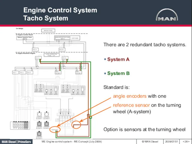
- 28. Engine Control System Tacho System There are 2 redundant tacho systems. System B System A Standard
- 29. Tacho System
- 30. Tacho System Angle Encoders 90 deg ATDC Angle encoder A Angle encoder B
- 31. Tacho system Angle encoder A + B System A (powered from ECU A) MMA = Marker
- 32. Tacho System, Angle Encoders
- 33. Tacho System Amplifier Boxes, TSA
- 34. Tacho System, Semicircular Ring
- 35. Tacho System, Master Slave A, MSA, on AFT end of Engine
- 36. Tacho System Trigger Rings + Sensors (option) Triggersegment with a sine-curved tooth-profile The total trigger ring
- 37. Performance By changing the exh. valve closing timing, the Pcomp can be adjusted, and then the
- 38. Pscav, Pcomp & Pmax
- 40. Скачать презентацию
< >
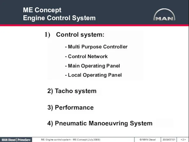
Control system:
- Multi Purpose Controller
- Control Network
- Main Operating Panel
-
< >
Control system:
- Multi Purpose Controller
- Control Network
- Main Operating Panel
-
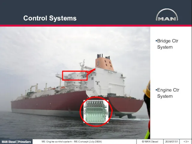
Control Systems
< >
Bridge Ctr System
Engine Ctr System
Control Systems
< >
Bridge Ctr System
Engine Ctr System
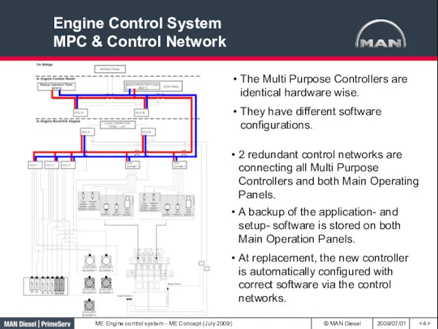
Engine Control System
MPC & Control Network
< >
2 redundant control networks are
Engine Control System
MPC & Control Network
< >
2 redundant control networks are
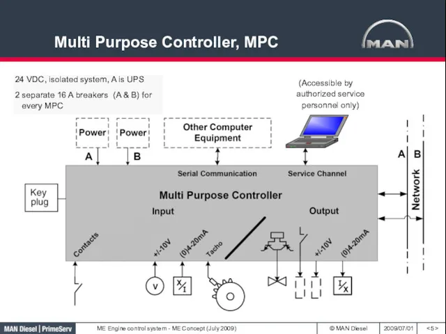
Multi Purpose Controller, MPC
< >
24 VDC, isolated system, A is
Multi Purpose Controller, MPC
< >
24 VDC, isolated system, A is
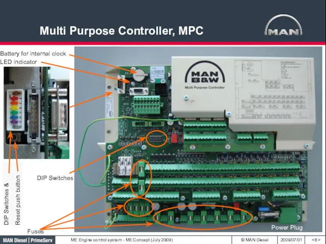
Multi Purpose Controller, MPC
< >
DIP Switches
DIP Switches &
Reset push button
Power Plug
Multi Purpose Controller, MPC
< >
DIP Switches
DIP Switches &
Reset push button
Power Plug
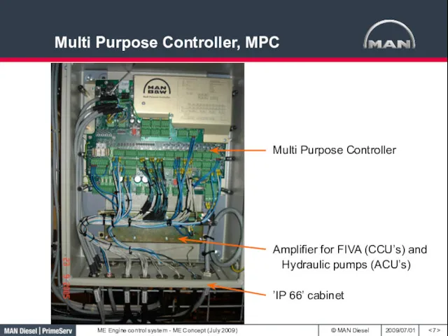
Multi Purpose Controller, MPC
< >
Amplifier for FIVA (CCU’s) and Hydraulic pumps
Multi Purpose Controller, MPC
< >
Amplifier for FIVA (CCU’s) and Hydraulic pumps
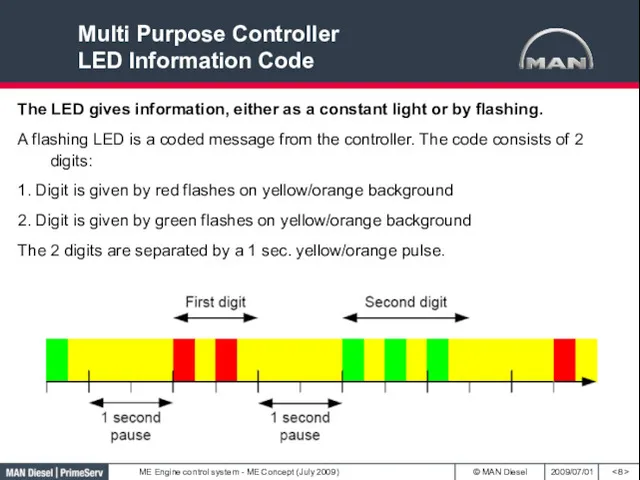
Multi Purpose Controller
LED Information Code
< >
The LED gives information, either
Multi Purpose Controller
LED Information Code
< >
The LED gives information, either
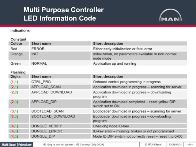
Multi Purpose Controller
LED Information Code
< >
Multi Purpose Controller
LED Information Code
< >
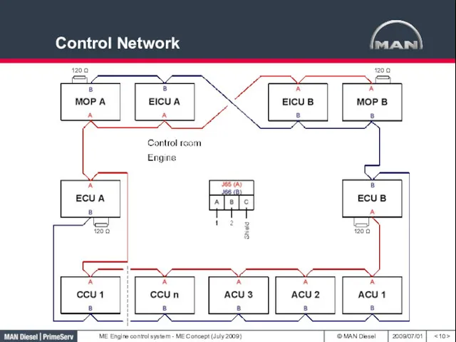
Control Network
< >
120 Ω
120 Ω
120 Ω
120 Ω
Control Network
< >
120 Ω
120 Ω
120 Ω
120 Ω
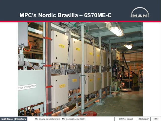
MPC’s Nordic Brasilia – 6S70ME-C
< >
MPC’s Nordic Brasilia – 6S70ME-C
< >
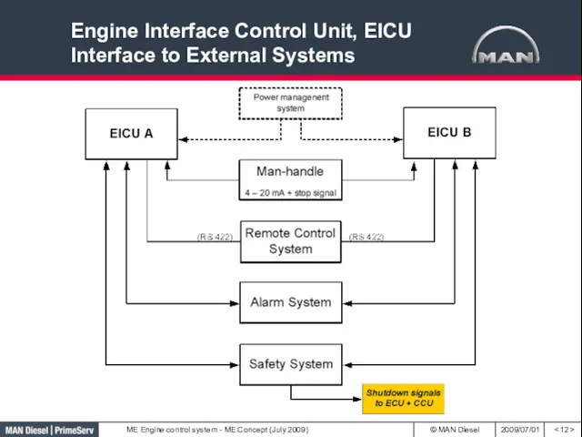
Engine Interface Control Unit, EICU
Interface to External Systems
< >
Engine Interface Control Unit, EICU
Interface to External Systems
< >
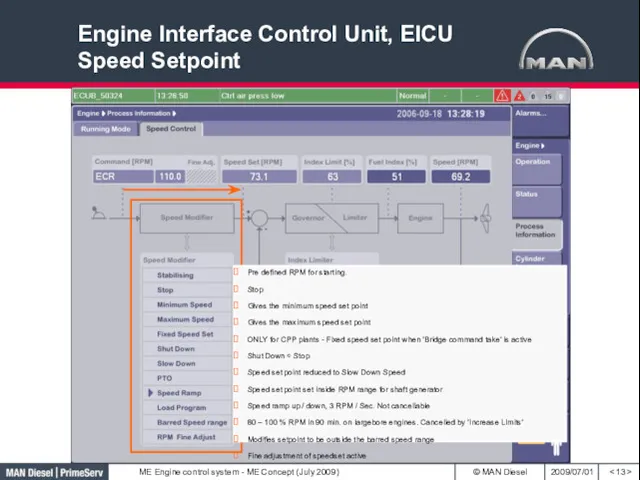
Engine Interface Control Unit, EICU Speed Setpoint
< >
Pre defined RPM for
Engine Interface Control Unit, EICU Speed Setpoint
< >
Pre defined RPM for
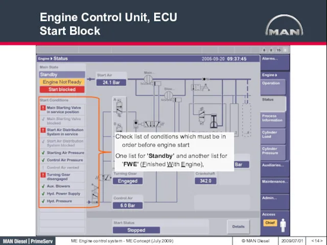
Engine Control Unit, ECU
Start Block
< >
Engine Control Unit, ECU
Start Block
< >
Engine Control Unit, ECU
< >
3 governor modes:
RPM – Torque -
Engine Control Unit, ECU
< >
3 governor modes:
RPM – Torque -
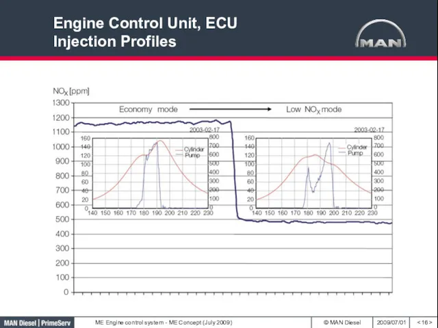
Engine Control Unit, ECU
Injection Profiles
< >
Engine Control Unit, ECU
Injection Profiles
< >
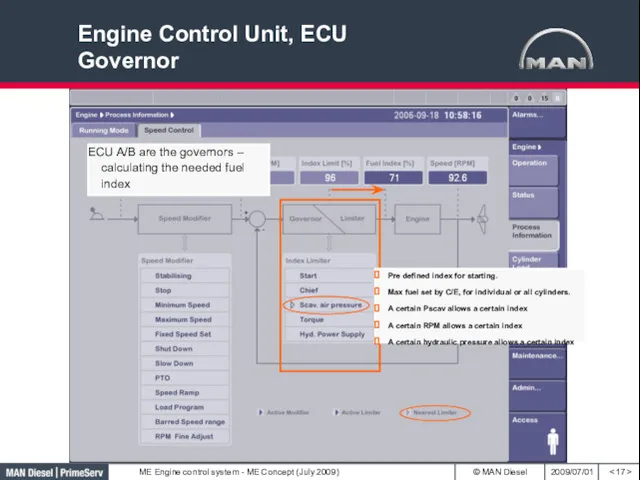
Engine Control Unit, ECU
Governor
< >
Pre defined index for starting.
Max fuel set
Engine Control Unit, ECU
Governor
< >
Pre defined index for starting.
Max fuel set
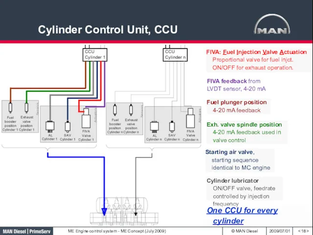
Cylinder Control Unit, CCU
< >
Fuel plunger position 4-20 mA feedback
Exh.
Cylinder Control Unit, CCU
< >
Fuel plunger position 4-20 mA feedback
Exh.
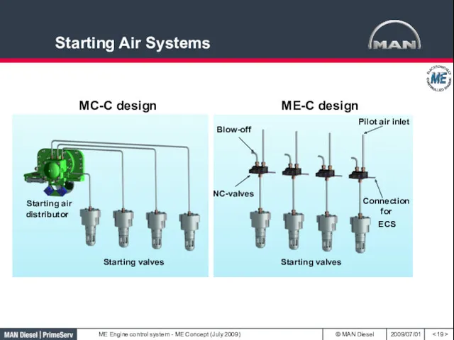
Starting Air Systems
< >
Starting Air Systems
< >
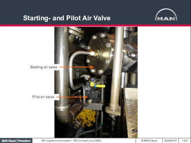
Starting- and Pilot Air Valve
< >
Starting- and Pilot Air Valve
< >
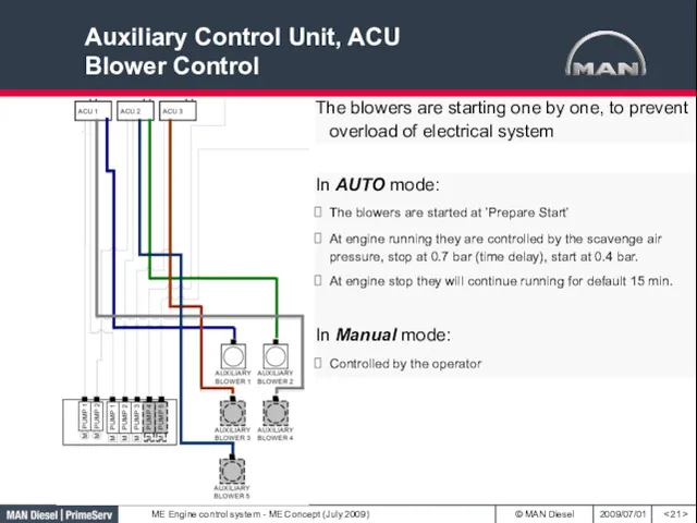
Auxiliary Control Unit, ACU
Blower Control
< >
The blowers are starting one by
Auxiliary Control Unit, ACU
Blower Control
< >
The blowers are starting one by
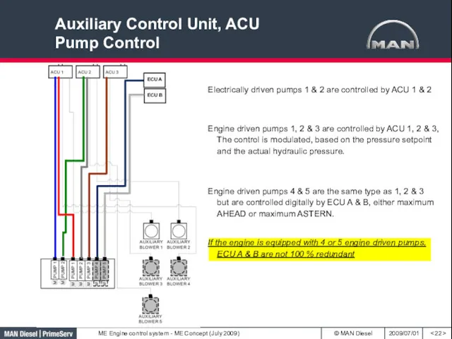
Auxiliary Control Unit, ACU
Pump Control
< >
Electrically driven pumps 1 & 2
Auxiliary Control Unit, ACU
Pump Control
< >
Electrically driven pumps 1 & 2
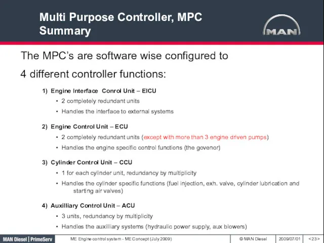
Multi Purpose Controller, MPC
Summary
< >
The MPC’s are software wise configured to
4
Multi Purpose Controller, MPC
Summary
< >
The MPC’s are software wise configured to
4
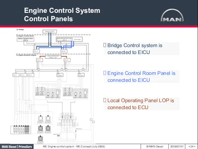
Engine Control System
Control Panels
< >
Bridge Control system is connected to EICU
Engine
Engine Control System
Control Panels
< >
Bridge Control system is connected to EICU
Engine
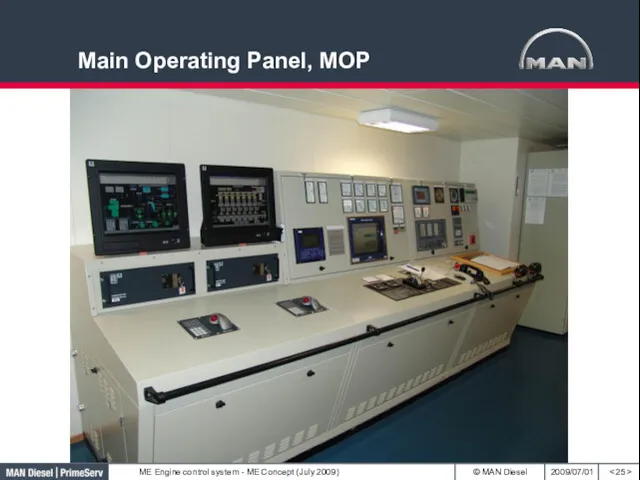
Main Operating Panel, MOP
< >
Main Operating Panel, MOP
< >
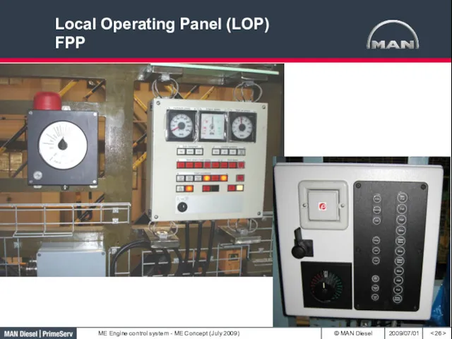
Local Operating Panel (LOP)
FPP
< >
Local Operating Panel (LOP)
FPP
< >
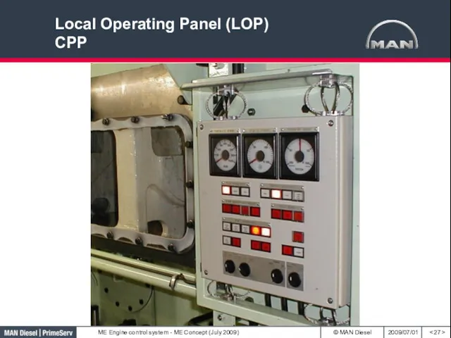
Local Operating Panel (LOP)
CPP
< >
Local Operating Panel (LOP)
CPP
< >
Engine Control System
Tacho System
< >
There are 2 redundant tacho systems.
System B
System
Engine Control System
Tacho System
< >
There are 2 redundant tacho systems.
System B
System
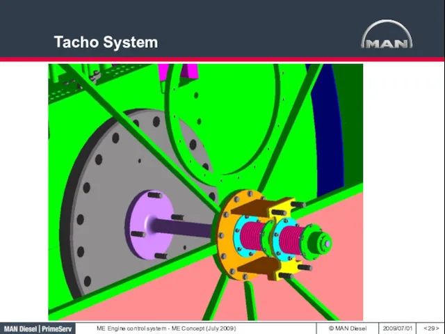
Tacho System
< >
Tacho System
< >
Tacho System
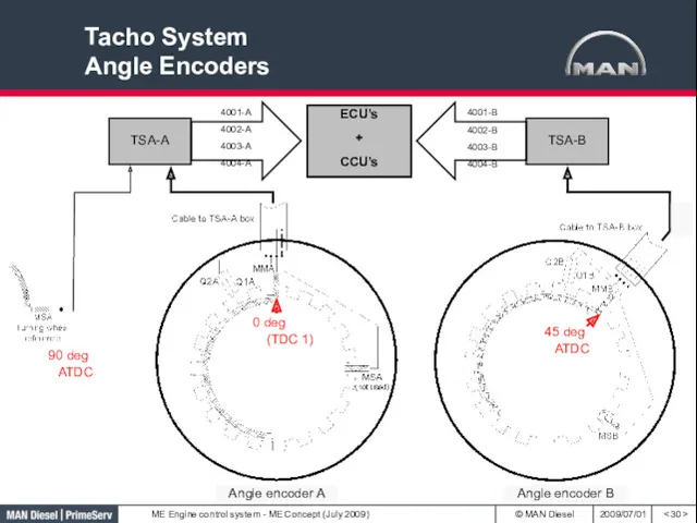
Angle Encoders
< >
90 deg ATDC
Angle encoder A
Angle encoder B
Tacho System
Angle Encoders
< >
90 deg ATDC
Angle encoder A
Angle encoder B
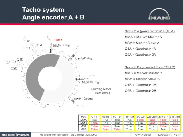
Tacho system
Angle encoder A + B
< >
System A (powered from ECU
Tacho system
Angle encoder A + B
< >
System A (powered from ECU
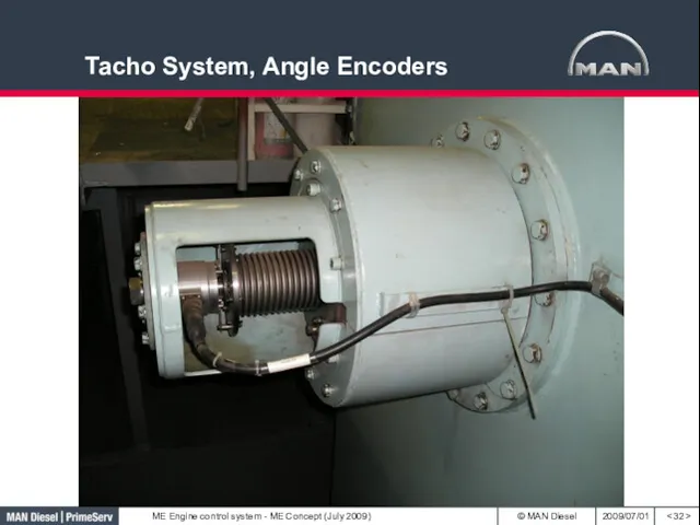
Tacho System, Angle Encoders
< >
Tacho System, Angle Encoders
< >
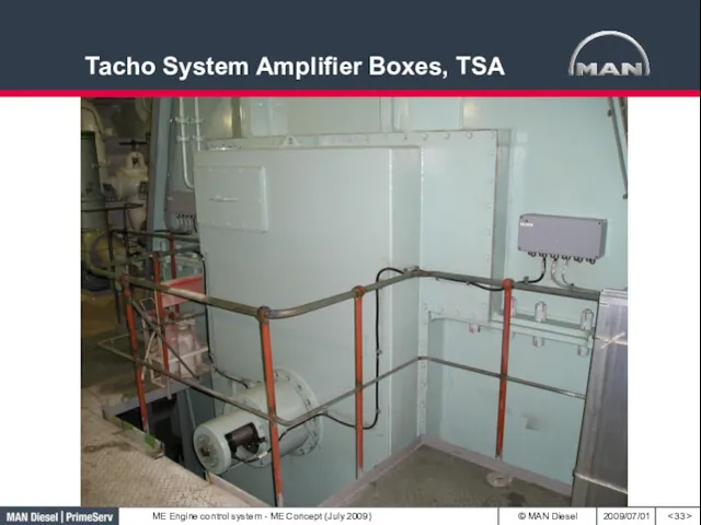
Tacho System Amplifier Boxes, TSA
< >
Tacho System Amplifier Boxes, TSA
< >
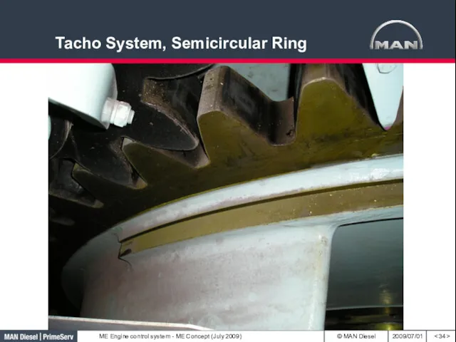
Tacho System, Semicircular Ring
< >
Tacho System, Semicircular Ring
< >
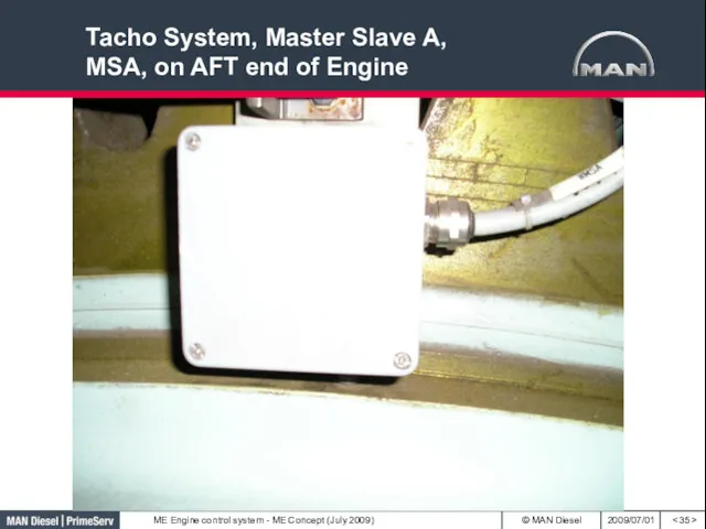
Tacho System, Master Slave A, MSA, on AFT end of Engine
<
Tacho System, Master Slave A, MSA, on AFT end of Engine
<
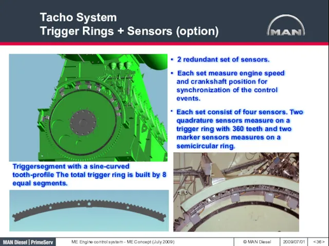
Tacho System
Trigger Rings + Sensors (option)
< >
Triggersegment with a sine-curved tooth-profile
Tacho System
Trigger Rings + Sensors (option)
< >
Triggersegment with a sine-curved tooth-profile
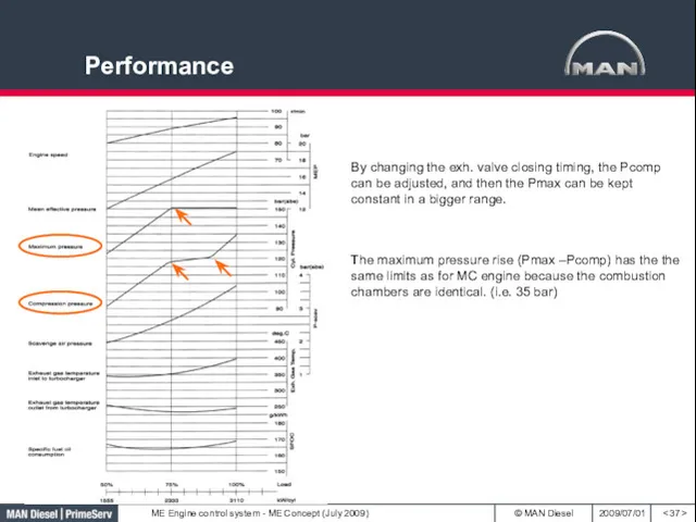
Performance
< >
By changing the exh. valve closing timing, the Pcomp can
Performance
< >
By changing the exh. valve closing timing, the Pcomp can
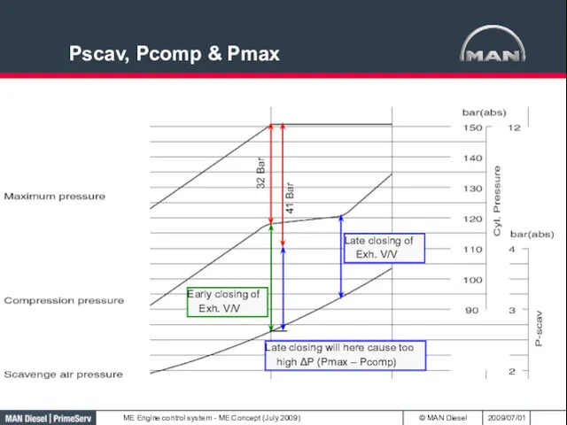
Pscav, Pcomp & Pmax
Pscav, Pcomp & Pmax
 Сказочки-шумелки. Зима в лесу
 Контроль условий, процессов и результатов образовательной деятельности
 Презентация- игра Гербы городов Липецкой области
 Презентация. Развитие мелкой моторики с помощью дидактических игр в разных областях образовательной деятельности.
 Мастер-класс Силуэты
 Наши права и обязанности
 Лоскутное шитье
 Проблемы управления политикой спроса
 Человеческий капитал ТЭК. Роль ТЭК в экономике страны
 Познавательный проект Славяне
 Внеклассное занятие Легенды и мифы Санкт-Петербурга 2 класс
 Ценовая эластичность спроса. Эластичность спроса и доход производителей
 Инвестиционная деятельность предприятия ПАО КАМАЗ Автомобильный завод
 Что должен уметь ребенок 3-4 лет
 Прямоугольная система координат
 Хирургиядағы ақпаратты-компьютерлік технологиялар телемедицинасы
 Расстройства аутистического спектра
 Наркомания
 Етика та естетика. Етика ділових відносин. Етикет
 АСК 2 урок Природные особенности Смоленской области
 Организация различных видов деятельности и общения детей. Практика
 Презентация От Коперника до наших дней
 презентация к родительскому собранию Агрессия детей, ее причины и предупреждение
 Проект Живая азбука
 Дружат дети всей Земли Диск
 Презентация. Роль ИКТ в формировании познавательной сферы обучающихся, развитие логического мышления
 Педагогические технологии
 Тест по теме СОСТОЯНИЯ ВЕЩЕСТВА, 5 класс