- Jets in flight

Содержание
- 2. Designing a Navy Jet Fighter
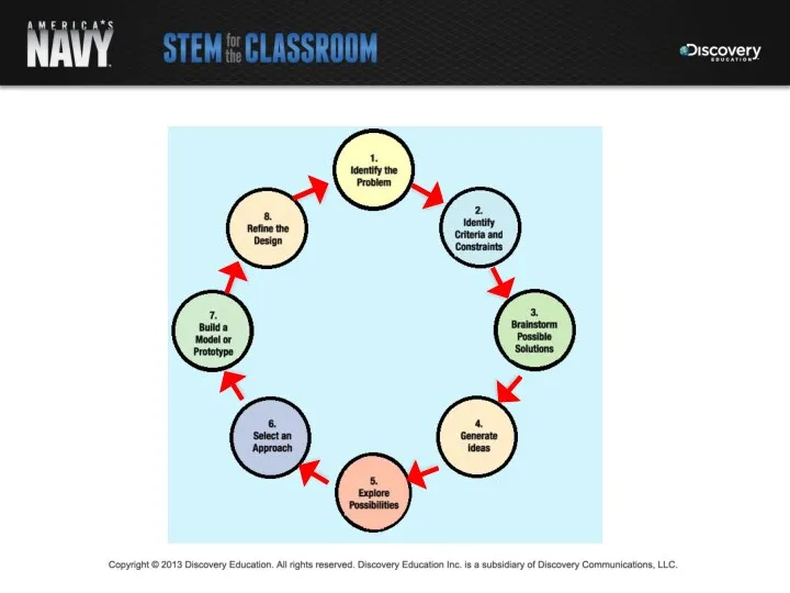
- 3. Lesson Objectives Understand the Engineering Design Process Comprehend the basic principles of flight Apply the Engineering
- 4. Navy Aviation
- 5. Lesson Goal Apply the principles of flight and the engineering design process to design and construct
- 6. Lesson Organization Part 1: Understanding and applying the basic principles of flight Part 2: Building a
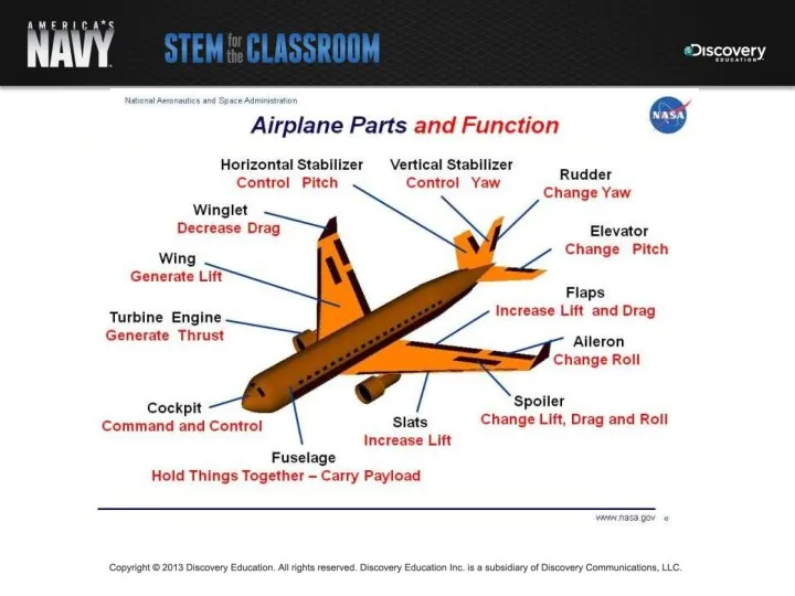
- 8. Vital for Flight
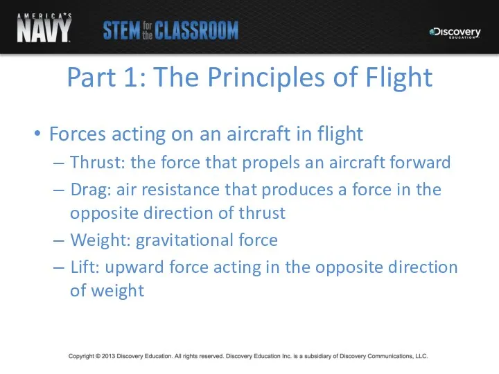
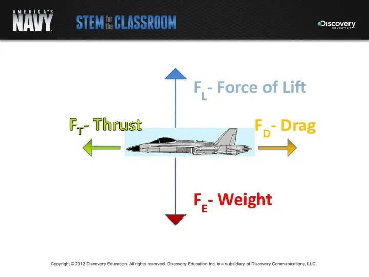
- 10. Part 1: The Principles of Flight Forces acting on an aircraft in flight Thrust: the force
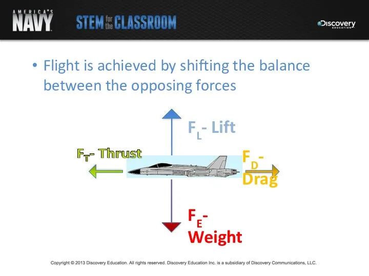
- 12. Flight is achieved by shifting the balance between the opposing forces
- 13. Thrust is produced in one of two ways: Transfer of momentum when gases are ejected to
- 14. Lift is the upward force created as air passes over and beneath the wings of an
- 15. Bernoulli’s Principle: 1. Fast moving air at the top edge of the wing creates a zone
- 16. Bernoulli’s Principle: 2. Slow moving air along the bottom edge of the wing has the same
- 17. Bernoulli’s Principle: 3. The difference in pressure creates the force of lift
- 18. Lift Momentum: additional upward force is generated incoming air deflects off the bottom of the wing
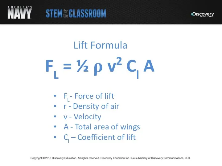
- 19. Lift Formula FL- Force of lift r - Density of air v - Velocity A -
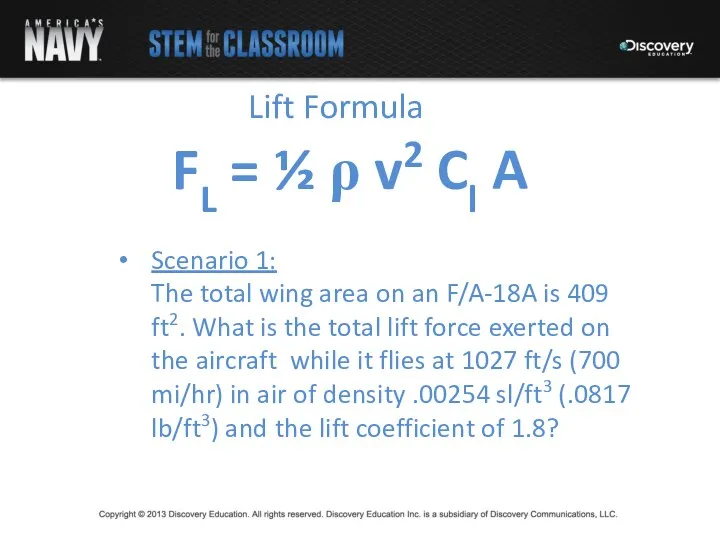
- 20. Lift Formula Scenario 1: The total wing area on an F/A-18A is 409 ft2. What is
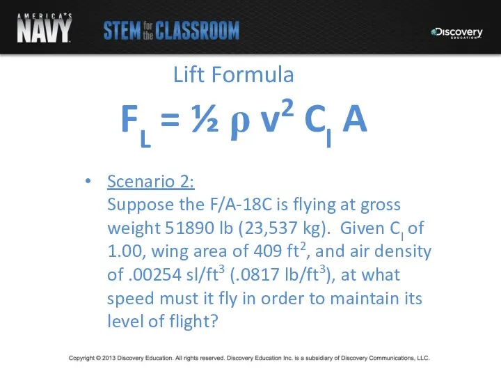
- 21. Lift Formula Scenario 2: Suppose the F/A-18C is flying at gross weight 51890 lb (23,537 kg).
- 22. Resources http://www.av8n.com/how/htm/4forces.html http://www.aerotraining.com/reference/AC%2061-23C_Chapter_1_Canada.pdf http://www.grc.nasa.gov/WWW/k-12/BGA/Sheri/the_lift_equation_act.htm http://www.fighter-planes.com/info/f18.ht http://www.grc.nasa.gov/WWW/K-12/airplane/foil2.html
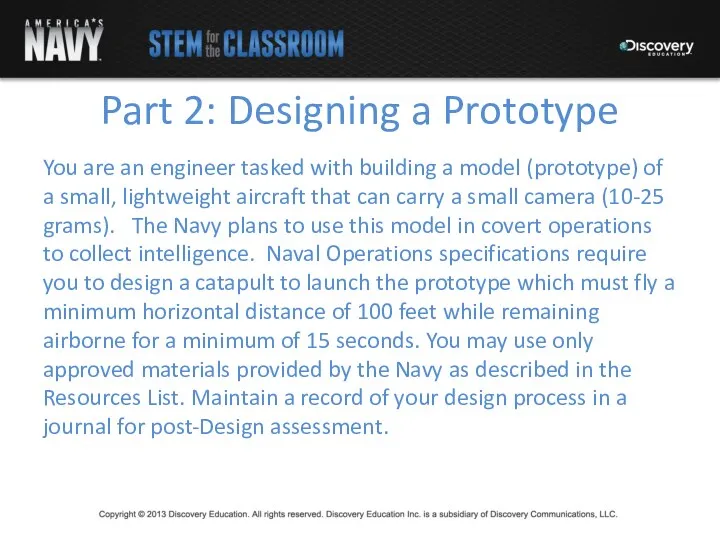
- 23. Part 2: Designing a Prototype You are an engineer tasked with building a model (prototype) of
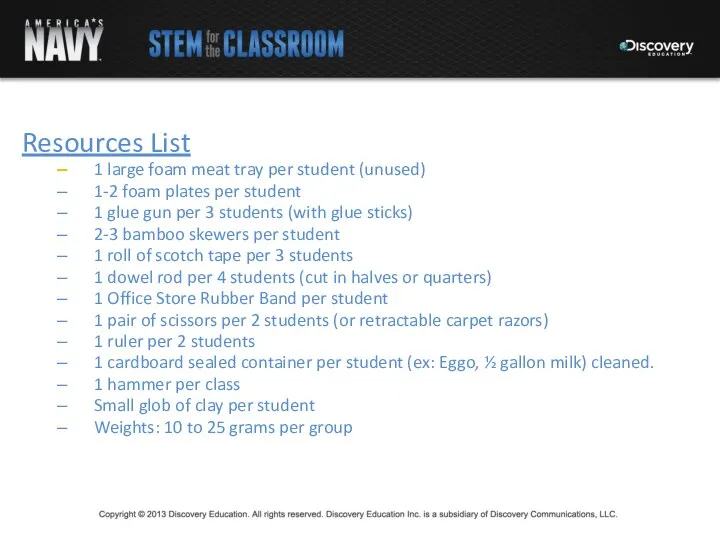
- 24. Resources List 1 large foam meat tray per student (unused) 1-2 foam plates per student 1
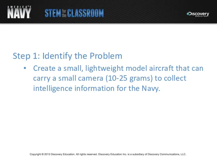
- 26. Step 1: Identify the Problem Create a small, lightweight model aircraft that can carry a small
- 27. Step 2: Identify Criteria and Constraints Fly at least 100 feet horizontally Maintain flight for at
- 29. Скачать презентацию
Designing a Navy Jet Fighter
Designing a Navy Jet Fighter
Lesson Objectives
Understand the Engineering Design Process
Comprehend the basic principles of flight
Apply
Lesson Objectives
Understand the Engineering Design Process
Comprehend the basic principles of flight
Apply
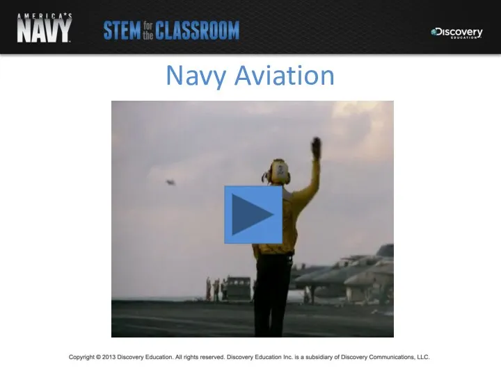
Navy Aviation
Navy Aviation
Lesson Goal
Apply the principles of flight and the engineering design process
Lesson Goal
Apply the principles of flight and the engineering design process
Lesson Organization
Part 1: Understanding and applying the basic principles of flight
Part
Lesson Organization
Part 1: Understanding and applying the basic principles of flight
Part
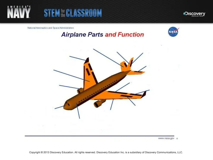
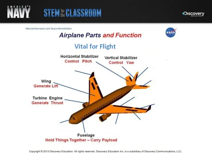
Vital for Flight
Vital for Flight
Part 1: The Principles of Flight
Forces acting on an aircraft in
Part 1: The Principles of Flight
Forces acting on an aircraft in
Flight is achieved by shifting the balance between the opposing forces
Flight is achieved by shifting the balance between the opposing forces
Thrust is produced in one of two ways:
Transfer of momentum when
Thrust is produced in one of two ways:
Transfer of momentum when
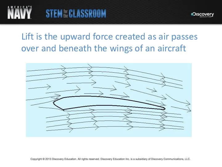
Lift is the upward force created as air passes over and
Lift is the upward force created as air passes over and
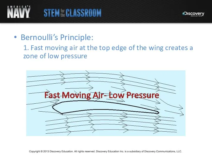
Bernoulli’s Principle:
1. Fast moving air at the top edge of the
Bernoulli’s Principle:
1. Fast moving air at the top edge of the
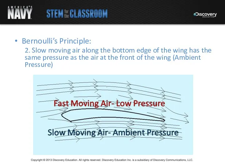
Bernoulli’s Principle:
2. Slow moving air along the bottom edge of the
Bernoulli’s Principle:
2. Slow moving air along the bottom edge of the
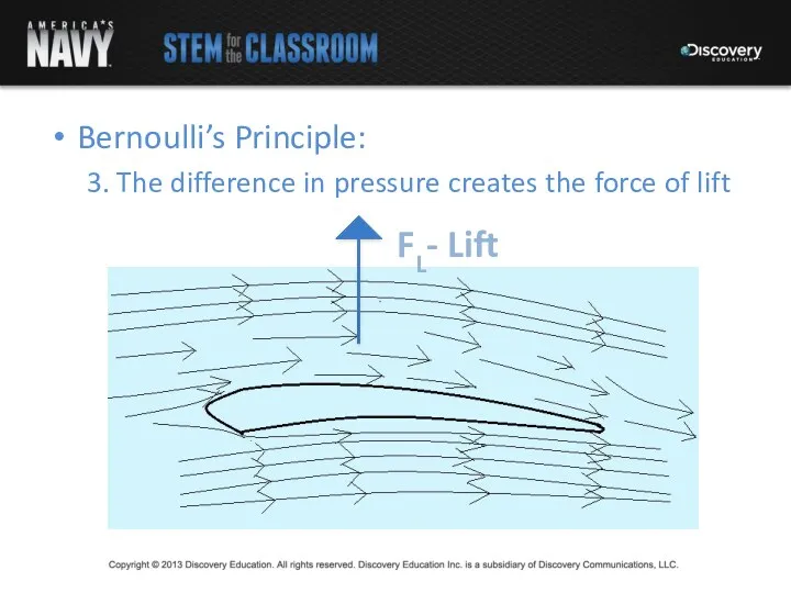
Bernoulli’s Principle:
3. The difference in pressure creates the force of lift
Bernoulli’s Principle:
3. The difference in pressure creates the force of lift
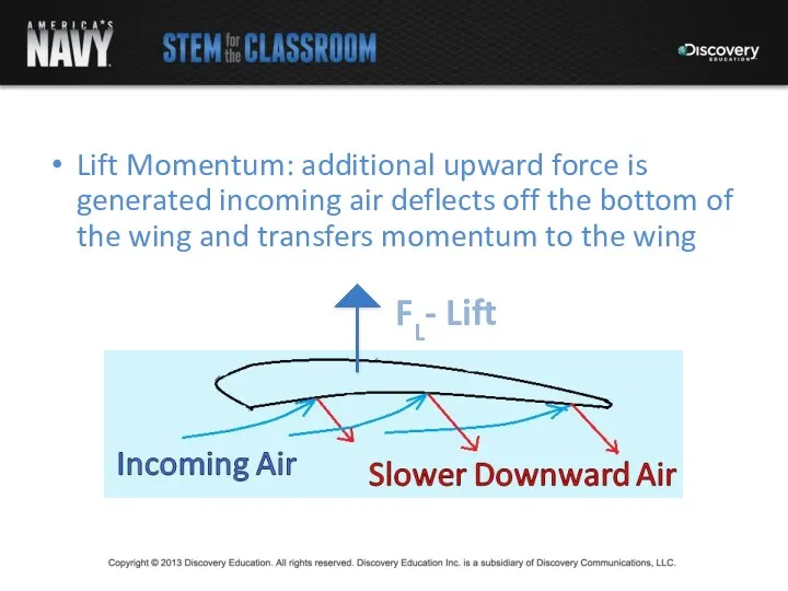
Lift Momentum: additional upward force is generated incoming air deflects off
Lift Momentum: additional upward force is generated incoming air deflects off
Lift Formula
FL- Force of lift
r - Density of air
v - Velocity
Lift Formula
FL- Force of lift
r - Density of air
v - Velocity
Lift Formula
Scenario 1:
The total wing area on an F/A-18A is 409
Lift Formula
Scenario 1:
The total wing area on an F/A-18A is 409
Lift Formula
Scenario 2:
Suppose the F/A-18C is flying at gross weight 51890
Lift Formula
Scenario 2:
Suppose the F/A-18C is flying at gross weight 51890
Resources
http://www.av8n.com/how/htm/4forces.html
http://www.aerotraining.com/reference/AC%2061-23C_Chapter_1_Canada.pdf
http://www.grc.nasa.gov/WWW/k-12/BGA/Sheri/the_lift_equation_act.htm
http://www.fighter-planes.com/info/f18.ht
http://www.grc.nasa.gov/WWW/K-12/airplane/foil2.html
Resources
http://www.av8n.com/how/htm/4forces.html
http://www.aerotraining.com/reference/AC%2061-23C_Chapter_1_Canada.pdf
http://www.grc.nasa.gov/WWW/k-12/BGA/Sheri/the_lift_equation_act.htm
http://www.fighter-planes.com/info/f18.ht
http://www.grc.nasa.gov/WWW/K-12/airplane/foil2.html
Part 2: Designing a Prototype
You are an engineer tasked with building
Part 2: Designing a Prototype
You are an engineer tasked with building
Resources List
1 large foam meat tray per student (unused)
1-2 foam
Resources List
1 large foam meat tray per student (unused)
1-2 foam
Step 1: Identify the Problem
Create a small, lightweight model aircraft that
Step 1: Identify the Problem
Create a small, lightweight model aircraft that
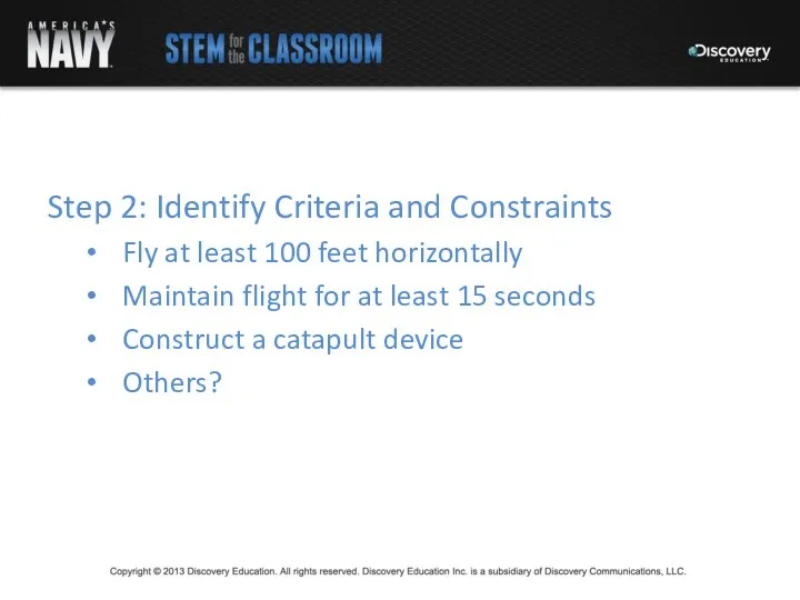
Step 2: Identify Criteria and Constraints
Fly at least 100 feet horizontally
Maintain
Step 2: Identify Criteria and Constraints
Fly at least 100 feet horizontally
Maintain
 Физика в белом халате
 Дослідження впливу сумішей адсорбційних і пасивуючих інгібіторів на електрохімічну поведінку сталі у водно-сольових розчинах
 Колесные пары электровозов ВЛ80, ВЛ85, 2ЭС5К
 Электрическое поле заряженных проводников. Энергия электростатического поля
 Устойчивость пластин
 Термометры и их виды
 Превращение одного вида энергии в другой
 сценарий линейки на день космонавтики
 Восстановление деталей синтетическими материалами
 Molecular-kinetic theory of ideal gases
 Тепловые двигатели и охрана окружающей среды
 Уравнение состояния идеального газа. Газовые законы
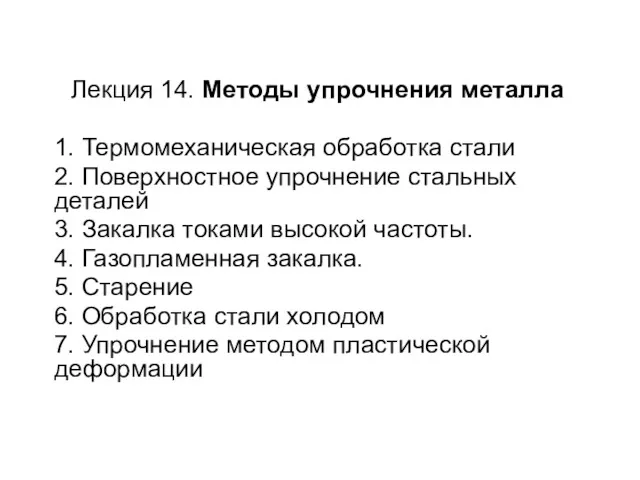 Методы упрочнения металла
 Неподвижные элементы и неисправности газораспределительных механизмов
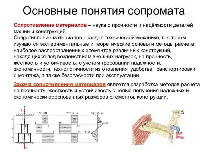 Основные понятия сопромата. Лекция 1
 Викторина для 11 класса
 Радиоволны
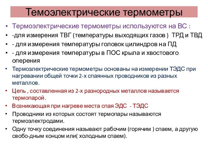 Термоэлектрические термометры
 Магнитное поле Земли
 История изобретения турбин
 Сила трения
 Ионизация газа
 Жылуалмасу аппараттарын есептеу
 Сопротивление материалов. Растяжение, сжатие, кручение
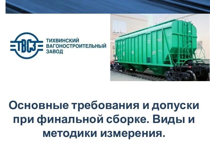 Основные требования и допуски при финальной сборке. Виды и методики измерения
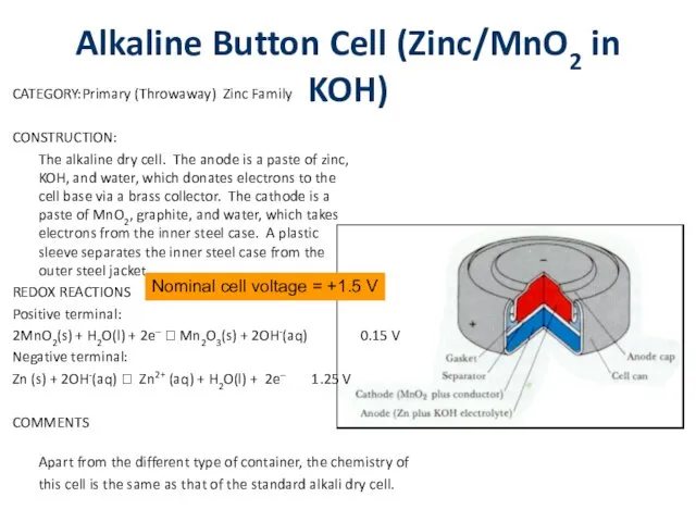 Alkaline Button Cell (Zinc/MnO2 in KOH)
 Газораспределительный механизм двигателя
 Физика и Автомобиль