- Crystal Defects and Noncrystalline Structure–Imperfection

Содержание
- 2. In our pervious Lecture when discussing Crystals we ASSUMED PERFECT ORDER In real materials we find:
- 3. Forming a liquid solution of water and alcohol. Mixing occurs on the molecular scale. We can
- 4. • Vacancies: -vacant atomic sites in a structure. • Self-Interstitials: -"extra" atoms positioned between atomic sites.
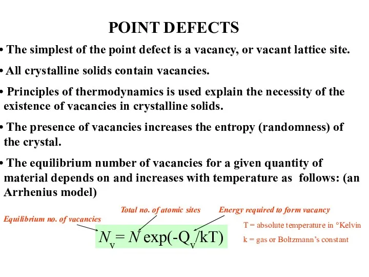
- 5. POINT DEFECTS The simplest of the point defect is a vacancy, or vacant lattice site. All
- 6. Two outcomes if impurity (B) added to host (A): • Solid solution of B in A
- 7. Solid solution of nickel in copper shown along a (100) plane. This is a substitutional solid
- 8. Imperfections in Solids Conditions for substitutional solid solution (S.S.) Hume – Rothery rules 1. Δr (atomic
- 9. Imperfections in Solids Application of Hume–Rothery rules – Solid Solutions 1. Would you predict more Al
- 10. Imperfections in Solids Specification of composition weight percent m1 = mass of component 1 nm1 =
- 11. Wt. % and At. % -- An example
- 12. Converting Between: (Wt% and At%) Converts from wt% to At% (Ai is atomic weight) Converts from
- 13. Interstitial solid solution applies to carbon in α-iron. The carbon atom is small enough to fit
- 14. Random, substitution solid solution can occur in Ionic Crystalline materials as well. Here of NiO in
- 15. A substitution solid solution of Al2O3 in MgO is not as simple as the case of
- 16. Iron oxide, Fe1−xO with x ≈ 0.05, is an example of a nonstoichiometric compound. Similar to
- 17. • Frenkel Defect --a cation is out of place. • Shottky Defect --a paired set of
- 18. And: • slip between crystal planes result when dislocations move, • this motion produces permanent (plastic)
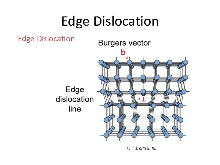
- 19. Linear Defects (Dislocations) Are one-dimensional defects around which atoms are misaligned Edge dislocation: extra half-plane of
- 20. Edge Dislocation Fig. 4.3, Callister 7e. Edge Dislocation
- 21. Definition of the Burgers vector, b, relative to an edge dislocation. (a) In the perfect crystal,
- 22. Screw dislocation. The spiral stacking of crystal planes leads to the Burgers vector being parallel to
- 23. Mixed dislocation. This dislocation has both edge and screw character with a single Burgers vector consistent
- 24. Burgers vector for the aluminum oxide structure. The large repeat distance in this relatively complex structure
- 25. Imperfections in Solids Dislocations are visible in (T) electron micrographs Adapted from Fig. 4.6, Callister 7e.
- 26. Dislocations & Crystal Structures • Structure: close-packed planes & directions are preferred. view onto two close-packed
- 27. One case is a twin boundary (plane) Essentially a reflection of atom positions across the twinning
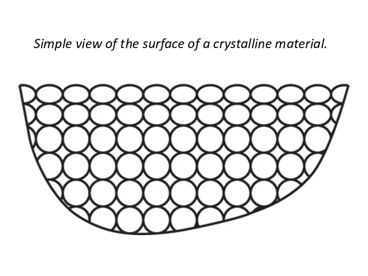
- 28. Simple view of the surface of a crystalline material.
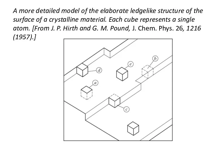
- 29. A more detailed model of the elaborate ledgelike structure of the surface of a crystalline material.
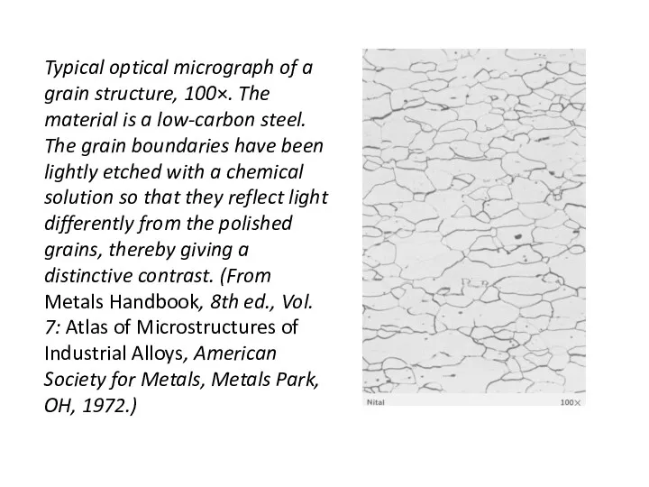
- 30. Typical optical micrograph of a grain structure, 100×. The material is a low-carbon steel. The grain
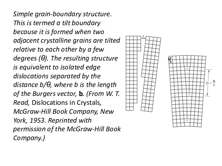
- 31. Simple grain-boundary structure. This is termed a tilt boundary because it is formed when two adjacent
- 32. The ledge Growth leads to structures with Grain Boundries The shape and average size or diameter
- 33. Specimen for the calculation of the grain-size number, G is defined at a magnification of 100×.
- 34. • Useful up to ~2000X magnification (?). • Polishing removes surface features (e.g., scratches) • Etching
- 35. Since Grain boundaries... • are planer imperfections, • are more susceptible to etching, • may be
- 36. ASTM (American Society for testing and Materials) VISUAL CHARTS (@100x) each with a number Quick and
- 37. Determining Grain Size, using a micrograph taken at 300x We count 14 grains in a 1
- 38. For this same material, how many Grains would I expect /in2 at 100x? At 50x?
- 39. At 100x
- 40. Two-dimensional schematics give a comparison of (a) a crystalline oxide and (b) a non-crystalline oxide. The
- 41. Bernal model of an amorphous metal structure. The irregular stacking of atoms is represented as a
- 42. A chemical impurity such as Na+ is a glass modifier, breaking up the random network and
- 43. Schematic illustration of medium-range ordering in a CaO–SiO2 glass. Edge-sharing CaO6 octahedra have been identified by
- 45. Скачать презентацию
In our pervious Lecture when discussing Crystals we
ASSUMED PERFECT ORDER
In
In our pervious Lecture when discussing Crystals we
ASSUMED PERFECT ORDER
In
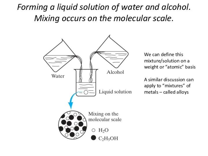
Forming a liquid solution of water and alcohol. Mixing occurs on
Forming a liquid solution of water and alcohol. Mixing occurs on
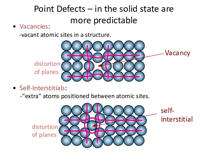
• Vacancies:
-vacant atomic sites in a structure.
• Self-Interstitials:
-"extra" atoms positioned between
• Vacancies:
-vacant atomic sites in a structure.
• Self-Interstitials:
-"extra" atoms positioned between
POINT DEFECTS
The simplest of the point defect is a vacancy,
POINT DEFECTS
The simplest of the point defect is a vacancy,

Two outcomes if impurity (B) added to host (A):
• Solid solution
Two outcomes if impurity (B) added to host (A):
• Solid solution

Solid solution of nickel in copper shown along a (100) plane.
Solid solution of nickel in copper shown along a (100) plane.
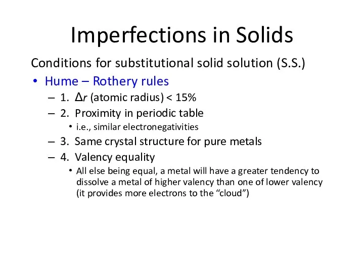
Imperfections in Solids
Conditions for substitutional solid solution (S.S.)
Hume – Rothery rules
1.
Imperfections in Solids
Conditions for substitutional solid solution (S.S.)
Hume – Rothery rules
1.
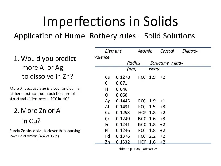
Imperfections in Solids
Application of Hume–Rothery rules – Solid Solutions
1. Would you
Imperfections in Solids
Application of Hume–Rothery rules – Solid Solutions
1. Would you
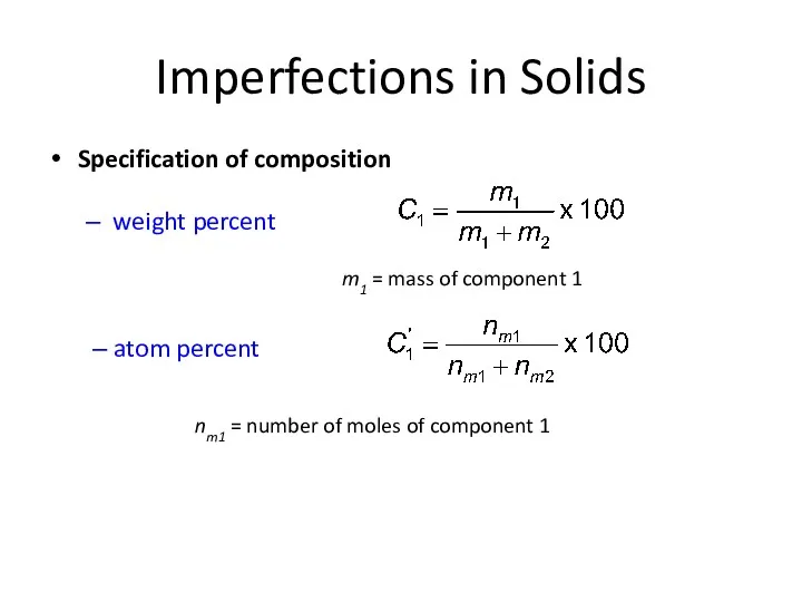
Imperfections in Solids
Specification of composition
weight percent
m1 = mass of component 1
nm1
Imperfections in Solids
Specification of composition
weight percent
m1 = mass of component 1
nm1

Wt. % and At. % -- An example
Wt. % and At. % -- An example

Converting Between: (Wt% and At%)
Converts from wt% to At% (Ai is
Converting Between: (Wt% and At%)
Converts from wt% to At% (Ai is
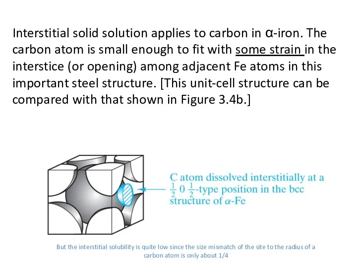
Interstitial solid solution applies to carbon in α-iron. The carbon atom
Interstitial solid solution applies to carbon in α-iron. The carbon atom
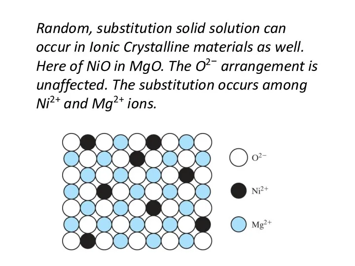
Random, substitution solid solution can occur in Ionic Crystalline materials as
Random, substitution solid solution can occur in Ionic Crystalline materials as

A substitution solid solution of Al2O3 in MgO is not as
A substitution solid solution of Al2O3 in MgO is not as
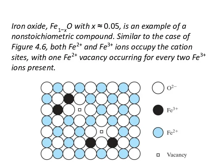
Iron oxide, Fe1−xO with x ≈ 0.05, is an example of
Iron oxide, Fe1−xO with x ≈ 0.05, is an example of

• Frenkel Defect
--a cation is out of place.
• Shottky Defect
• Frenkel Defect
--a cation is out of place.
• Shottky Defect
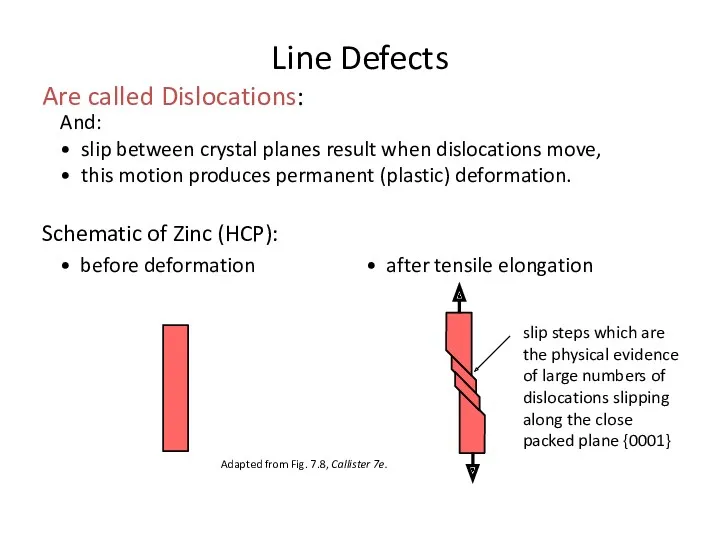
And:
• slip between crystal planes result when dislocations move,
• this motion
And:
• slip between crystal planes result when dislocations move,
• this motion
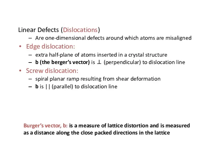
Linear Defects (Dislocations)
Are one-dimensional defects around which atoms are misaligned
Edge dislocation:
extra
Linear Defects (Dislocations)
Are one-dimensional defects around which atoms are misaligned
Edge dislocation:
extra
Edge Dislocation
Fig. 4.3, Callister 7e.
Edge Dislocation
Edge Dislocation
Fig. 4.3, Callister 7e.
Edge Dislocation
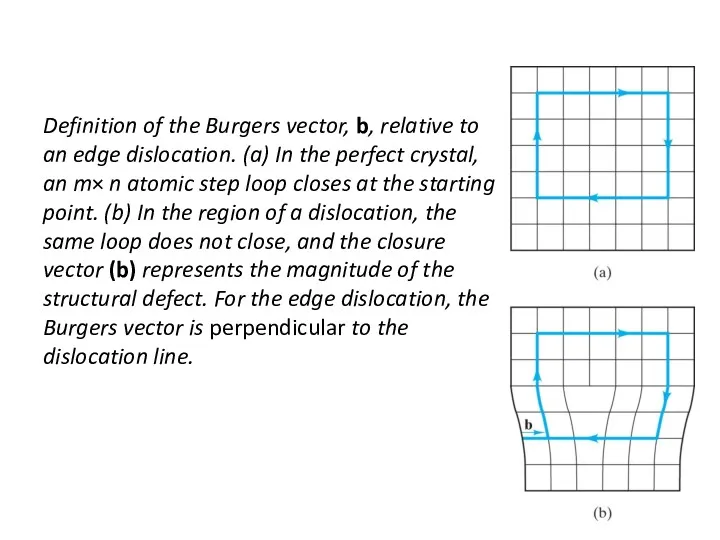
Definition of the Burgers vector, b, relative to an edge dislocation.
Definition of the Burgers vector, b, relative to an edge dislocation.
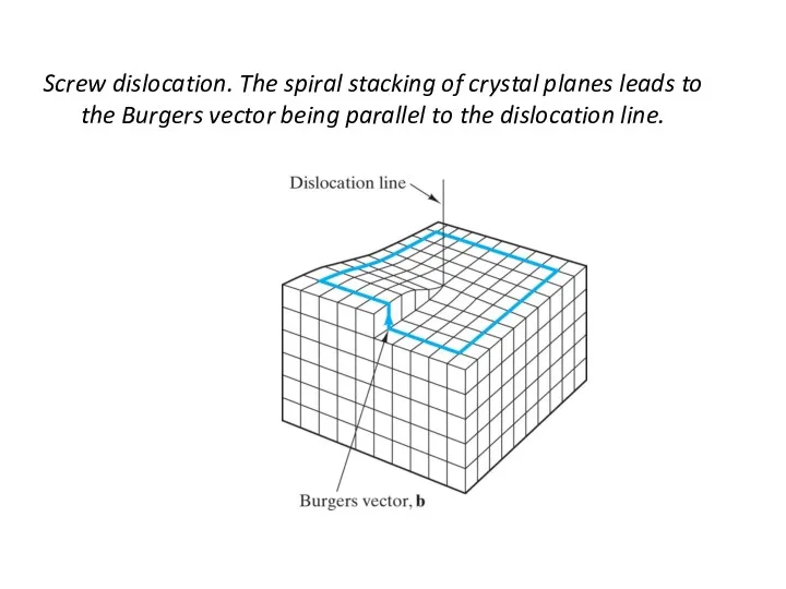
Screw dislocation. The spiral stacking of crystal planes leads to the
Screw dislocation. The spiral stacking of crystal planes leads to the
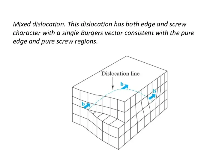
Mixed dislocation. This dislocation has both edge and screw character with
Mixed dislocation. This dislocation has both edge and screw character with
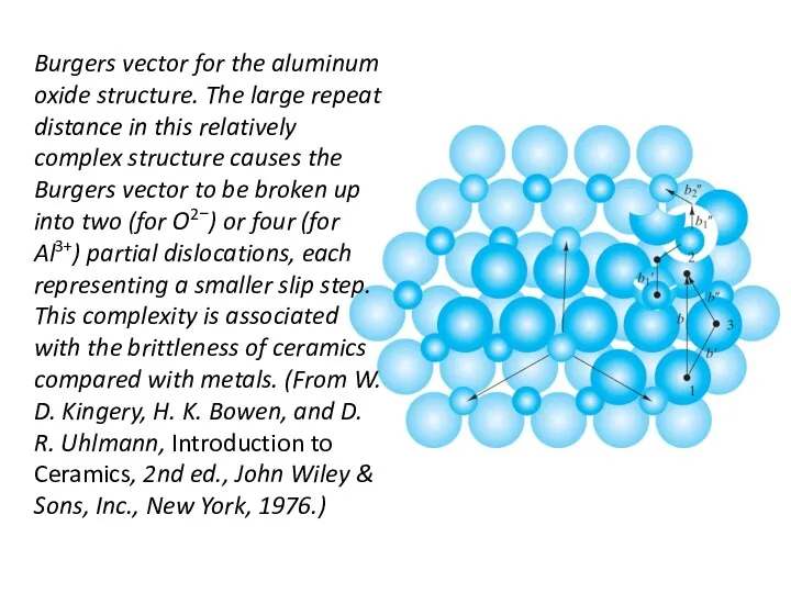
Burgers vector for the aluminum oxide structure. The large repeat distance
Burgers vector for the aluminum oxide structure. The large repeat distance
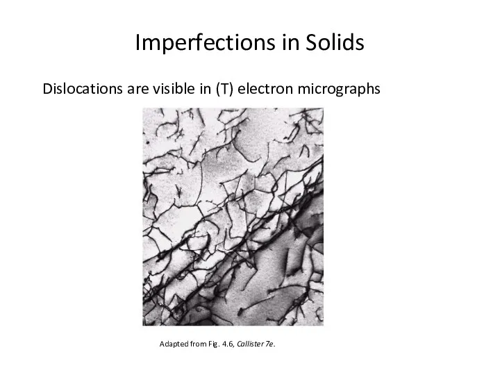
Imperfections in Solids
Dislocations are visible in (T) electron micrographs
Adapted from Fig.
Imperfections in Solids
Dislocations are visible in (T) electron micrographs
Adapted from Fig.
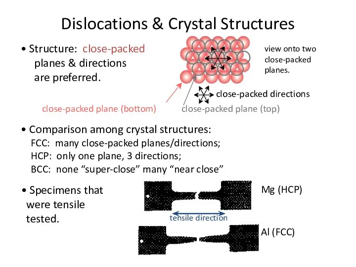
Dislocations & Crystal Structures
• Structure: close-packed
planes & directions
are preferred.
view
Dislocations & Crystal Structures
• Structure: close-packed
planes & directions
are preferred.
view
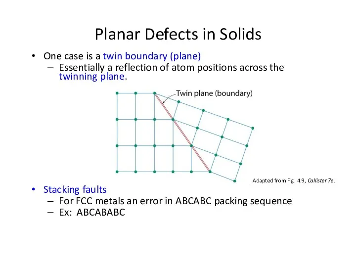
One case is a twin boundary (plane)
Essentially a reflection of
One case is a twin boundary (plane)
Essentially a reflection of
Simple view of the surface of a crystalline material.
Simple view of the surface of a crystalline material.
A more detailed model of the elaborate ledgelike structure of the
A more detailed model of the elaborate ledgelike structure of the
Typical optical micrograph of a grain structure, 100×. The material is
Typical optical micrograph of a grain structure, 100×. The material is
Simple grain-boundary structure. This is termed a tilt boundary because it
Simple grain-boundary structure. This is termed a tilt boundary because it
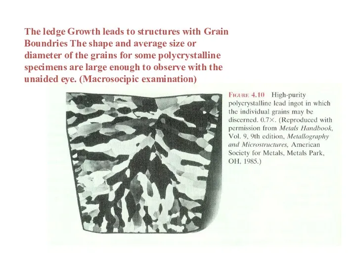
The ledge Growth leads to structures with Grain Boundries The shape
The ledge Growth leads to structures with Grain Boundries The shape
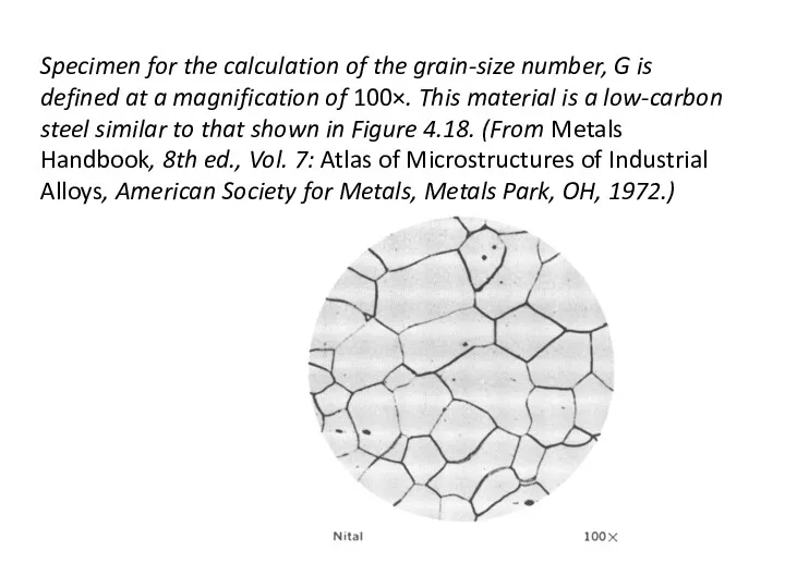
Specimen for the calculation of the grain-size number, G is defined
Specimen for the calculation of the grain-size number, G is defined
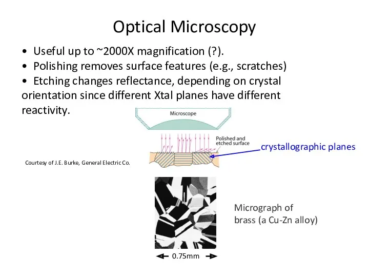
• Useful up to ~2000X magnification (?).
• Polishing removes surface features
• Useful up to ~2000X magnification (?).
• Polishing removes surface features
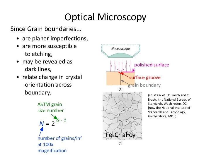
Since Grain boundaries...
• are planer imperfections,
• are more susceptible
to etching,
•
Since Grain boundaries...
• are planer imperfections,
• are more susceptible
to etching,
•
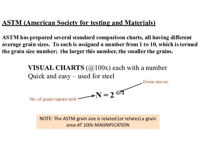
ASTM (American Society for testing and Materials)
VISUAL CHARTS (@100x) each with
ASTM (American Society for testing and Materials)
VISUAL CHARTS (@100x) each with
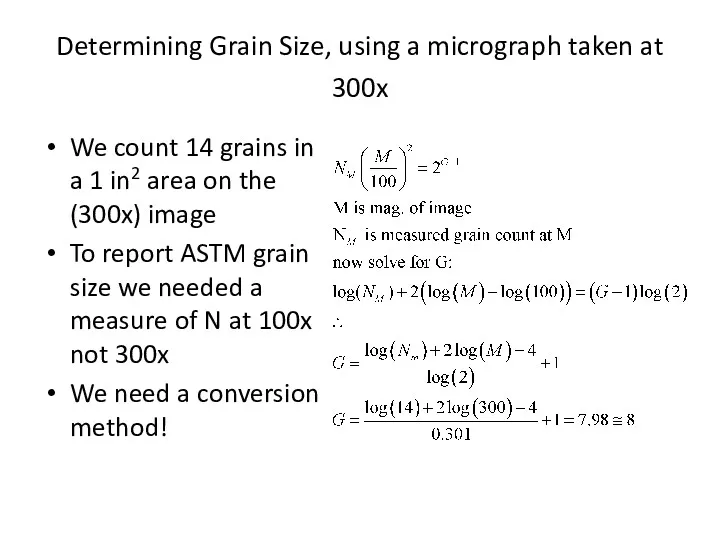
Determining Grain Size, using a micrograph taken at 300x
We count
Determining Grain Size, using a micrograph taken at 300x
We count

For this same material, how many Grains would I expect /in2
For this same material, how many Grains would I expect /in2

At 100x
At 100x
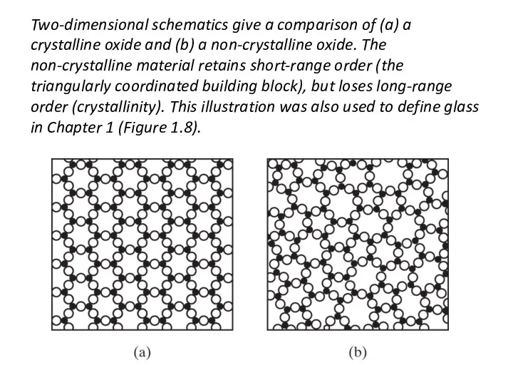
Two-dimensional schematics give a comparison of (a) a crystalline oxide and
Two-dimensional schematics give a comparison of (a) a crystalline oxide and
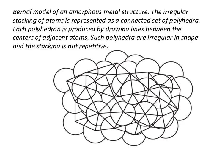
Bernal model of an amorphous metal structure. The irregular stacking of
Bernal model of an amorphous metal structure. The irregular stacking of
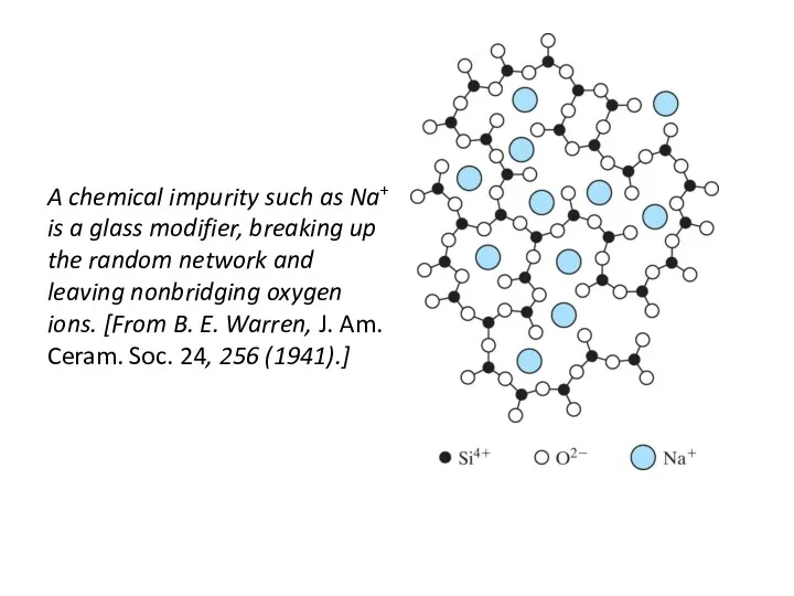
A chemical impurity such as Na+ is a glass modifier, breaking
A chemical impurity such as Na+ is a glass modifier, breaking
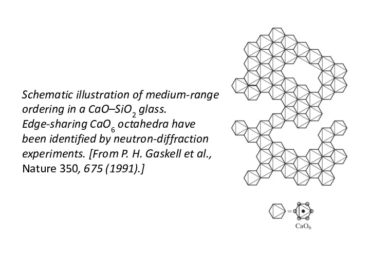
Schematic illustration of medium-range ordering in a CaO–SiO2 glass. Edge-sharing CaO6
Schematic illustration of medium-range ordering in a CaO–SiO2 glass. Edge-sharing CaO6
 Основные понятия органической химии
 Закон Авогадро. Молярный объем газов
 Нанотехнологии в школьном образовании. Семинар учителей химии
 Геохимические барьеры
 Высокомолекулярные соединения. Общий курс
 Фунгициды. Достоинства и недостати
 Кристаллические решетки. (8 класс)
 Стереоселективные синтезы
 Оптические свойства и методы исследования дисперсных систем. Лекция 16
 Электрондардың атомдарда орналасуы
 Химия вокруг нас
 Выделение ферментных препаратов методами осаждения и высаливания
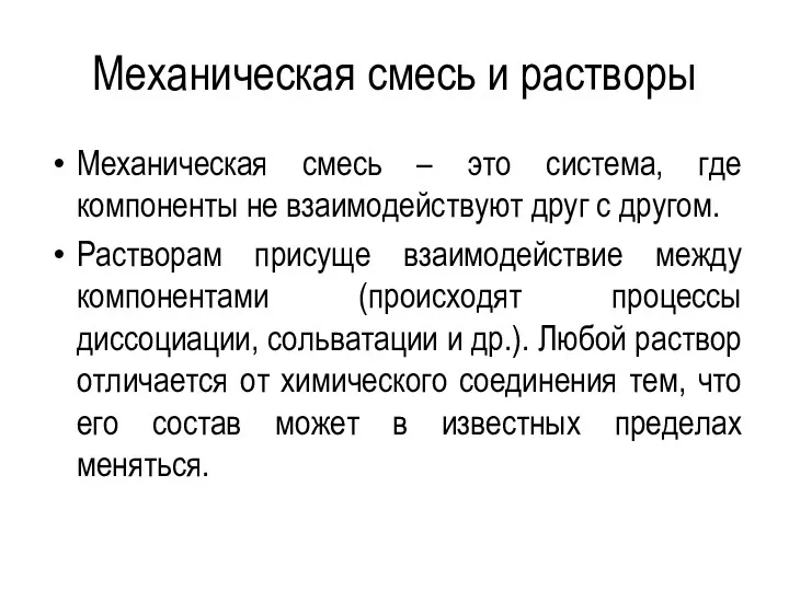 Механическая смесь и растворы
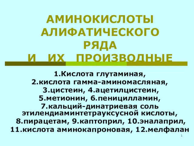 Аминокислоты алифатического ряда и их производные
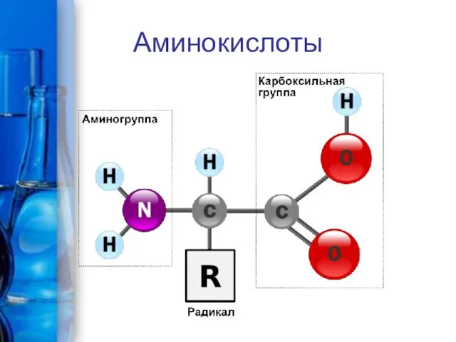 Аминокислоты и белки
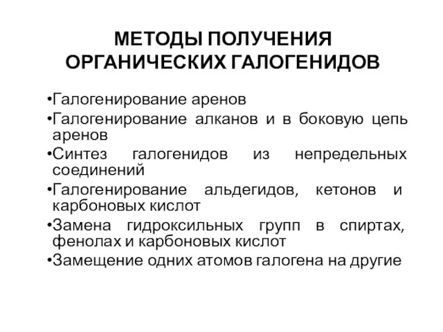 Методы получения органических галогенидов
 Поверхностные явления
 Фармацевтическая химия натрия гидрокарбоната
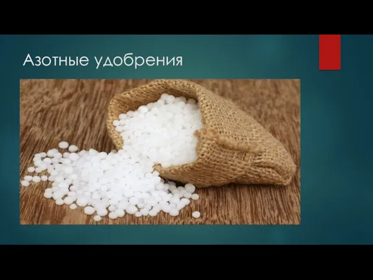 Азотные удобрения
 Номенклатура углеводородов: алканов алкенов алкинов. Создание учебного пособия
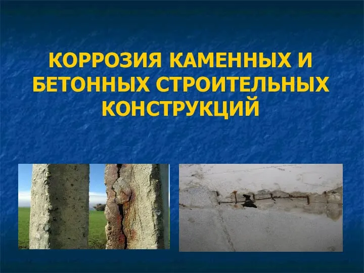 Коррозия каменных и бетонных строительных конструкций
 Химическая связь. Взаимное влияние атомов в молекуле. Классификация реакций и реагентов. Структура и функции биолекул
 Общие правила техники безопасности при работе в кабинете химии. Урок №2. Практическая работа №1
 Побочная подгруппа VIII группы периодической системы
 Химическая связь и ее типы. (11 класс)
 Особенности сжигания жидкого топлива и топливосжигающие устройства
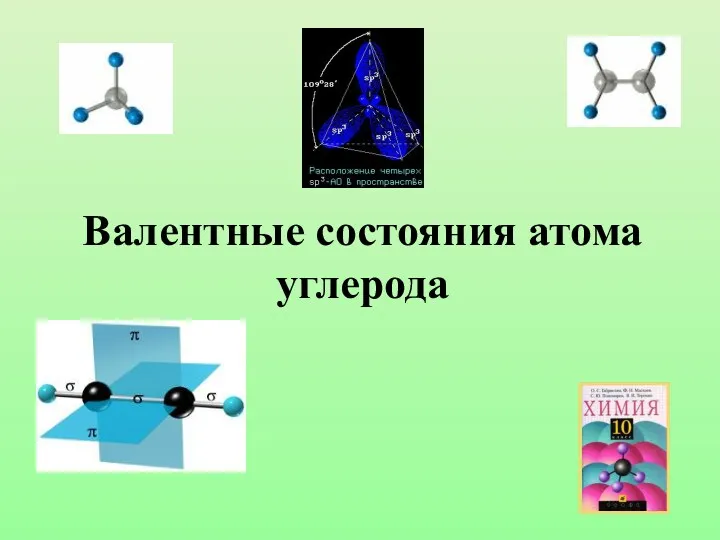 Валентные состояния атома углерода
 Химическая промышленность России