- Rigsite for LWD. (Lesson 11)

Содержание
- 2. Depth Measurement All LWD data depend on accurate depth measurements. Accurate depth monitoring is vital to
- 3. Depth Measurement Process Computer Depth sensors data are processed and added to the T/D dataset
- 4. Types of Failure or Error Mechanical failure Software failure Human Error Three possible ways to introduce
- 5. Accurate Depth Monitoring Vigilance catches depth errors at each connection Vigilance catches on/off bottom errors before
- 6. Time/Depth Datasets Entries in the time/depth dataset are tagged with a T/D activity and on/off bottom
- 7. Time/Depth Dataset
- 8. Activating the Depth Monitor If the icon is grayed out, the computer is not configured to
- 9. Depth Monitor
- 10. Depth Configuration
- 11. Changing T/D Activity
- 12. Changing T/D Activity
- 13. Logging Out of the Hole Set a new T/D activity in the depth monitor Used until
- 14. Surface Sensors Accurate calibration and reliable operation of surface sensors are critical to the LWD job.
- 15. Depth Calibration Enter the factors for installed sensors in this dialog box
- 16. Depth Calibration
- 17. Drawworks Calibration
- 18. Drawworks Calibration
- 19. Pipe Tally Sheet Copy the pipe joint lengths from the driller's pipe tally to the LWD
- 20. Using the Pipe Tally Sheet
- 21. Depth Control Review Importance of depth monitoring T/D dataset Depth monitor Depth configuration Depth calibration Pipe
- 22. Sources of Depth Errors Incorrect entry in tally sheet Driller used pipe out of order Not
- 23. Incorrect Entry in Tally Sheet First, check for errors in the tally sheet Possible sources of
- 24. Driller Used Pipe Out of Order The depth differences will even out after two or three
- 25. Pipe Used Out of Order Depth drilled = 95.71 ft Tally length stand 1 = 97.05
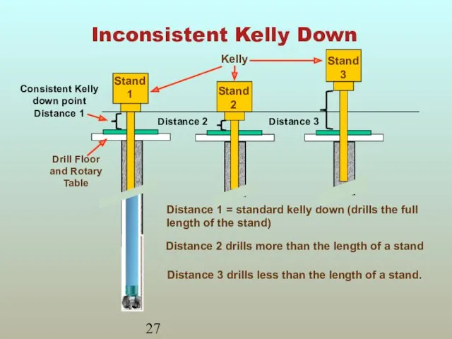
- 26. Inconsistent Kelly Down Drilled depth does not equal the length of the stand IDMS depth does
- 27. Inconsistent Kelly Down
- 28. Depth Calibration Error Same error showing up on each stand is a calibration error A small
- 29. Calibration Error Measurement Error - 0.58 ft Depth Error = - 0.58 ft Measurement Error -
- 30. On Bottom Early Spike in the ROP at beginning of a stand Positive hole depth error
- 31. On Bottom Early 6.11 ft hole depth error
- 32. On Bottom Late Caused by Less compression on pipe (less WOB) Error in sensor reading (slipping)
- 33. On Bottom Late
- 34. Crown Wheel Slipping Most likely to slip during fast movement of the drillstring Hot weather can
- 35. Crown Wheel Slipping Measurement Error - 0.58 ft Hole Depth Error = - 0.58 ft Measurement
- 36. Time/Depth Editor Functions Find Expand and compress Shift Insert and append Delete Edit single records Functions
- 37. Editing the Time/Depth Dataset Always back up the Time/Depth dataset before editing. After editing do a
- 38. T/D Editor
- 39. T/D Editor Graphic View
- 40. T/D Editor Graphic Functions
- 41. Time/Depth Review Sources of depth error Time/Depth editor layout Editing functions and when to use them
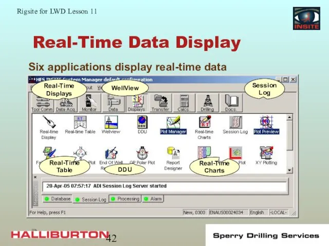
- 42. Real-Time Data Display Six applications display real-time data Real-Time Displays WellView Session Log Real-Time Table DDU
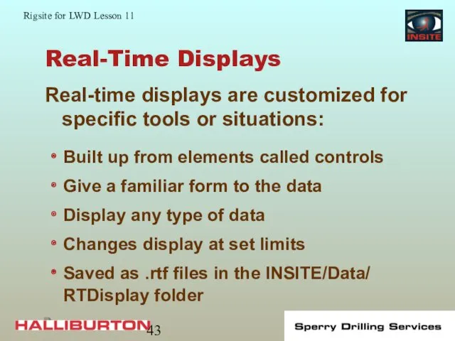
- 43. Real-Time Displays Real-time displays are customized for specific tools or situations: Built up from elements called
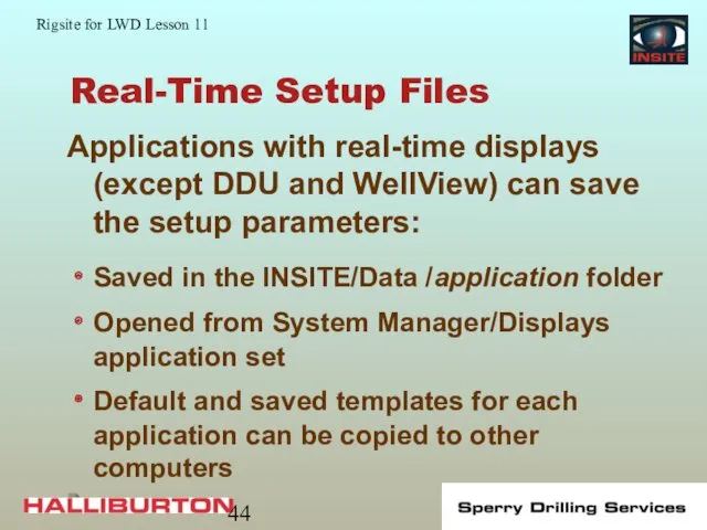
- 44. Real-Time Setup Files Applications with real-time displays (except DDU and WellView) can save the setup parameters:
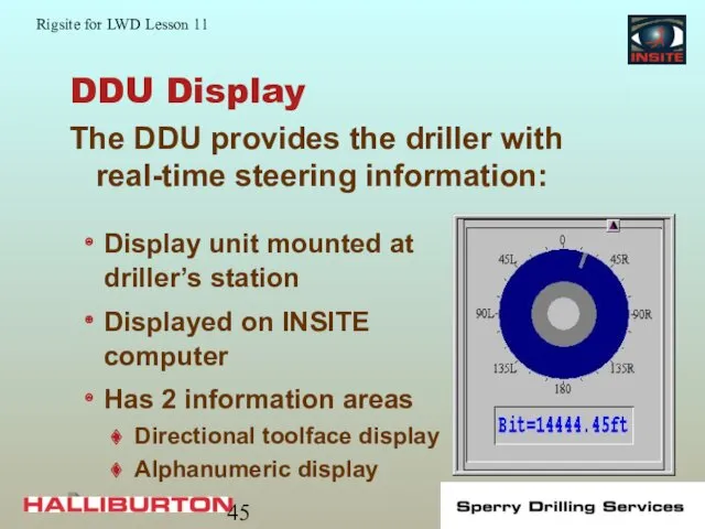
- 45. DDU Display The DDU provides the driller with real-time steering information: Display unit mounted at driller’s
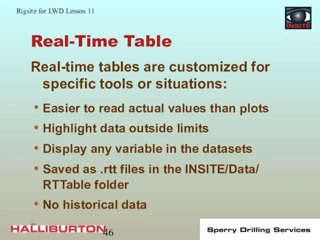
- 46. Real-Time Table Real-time tables are customized for specific tools or situations: Easier to read actual values
- 47. Real-Time Table Display
- 48. Real-Time Charts Real-time Charts: X,Y plot or bar chart of selected data Used to monitor critical
- 49. Real-Time Chart Example
- 50. Session Log Record of all information received and operations performed by INSITE: Scrolling sequential record of
- 51. Session Log continued Realtime or historical mode Can view previous Session Logs Previous Session Log files
- 52. Session Log Sequential Activity in INSITE
- 53. WellView WellView is a graphic presentation of the drilling track: Provides a visual display of well
- 54. WellView Example
- 55. Layout Layout provides a set up of real-time displays: Contains templates for different job situations Templates
- 56. Layout
- 57. Layout
- 58. Real-time Display Review DDU Tables Plots Session log Layout
- 60. Скачать презентацию
Depth Measurement
All LWD data depend on accurate depth measurements.
Accurate depth
Depth Measurement
All LWD data depend on accurate depth measurements.
Accurate depth
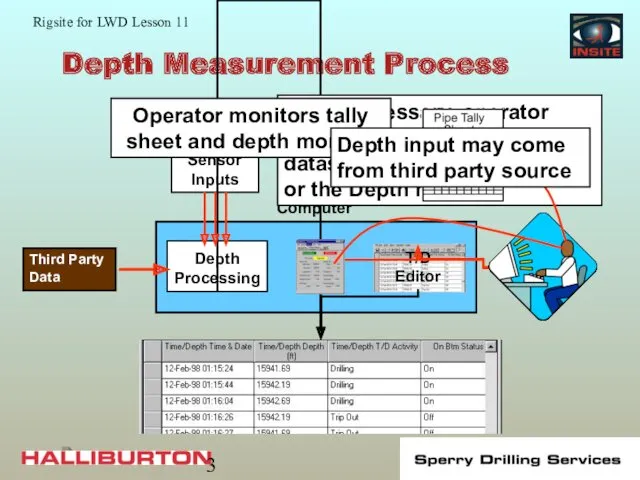
Depth Measurement Process
Computer
Depth sensors data are processed and added to the
Depth Measurement Process
Computer
Depth sensors data are processed and added to the
Types of Failure or Error
Mechanical failure
Software failure
Human Error
Three possible ways to
Types of Failure or Error
Mechanical failure
Software failure
Human Error
Three possible ways to
Accurate Depth Monitoring
Vigilance catches depth errors at each connection
Vigilance catches on/off
Accurate Depth Monitoring
Vigilance catches depth errors at each connection
Vigilance catches on/off
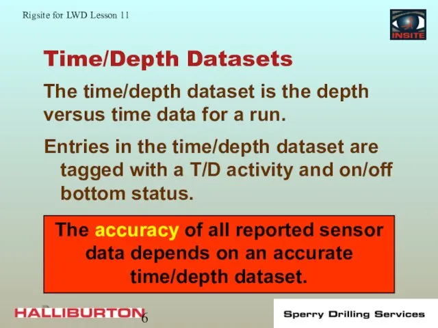
Time/Depth Datasets
Entries in the time/depth dataset are tagged with a T/D
Time/Depth Datasets
Entries in the time/depth dataset are tagged with a T/D
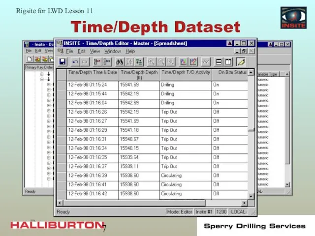
Time/Depth Dataset
Time/Depth Dataset
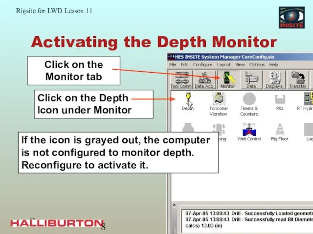
Activating the Depth Monitor
If the icon is grayed out, the computer
Activating the Depth Monitor
If the icon is grayed out, the computer
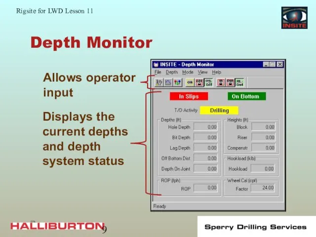
Depth Monitor
Depth Monitor
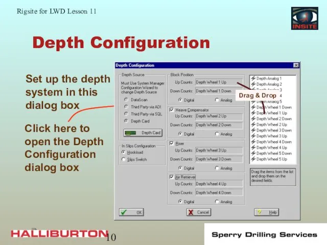
Depth Configuration
Depth Configuration
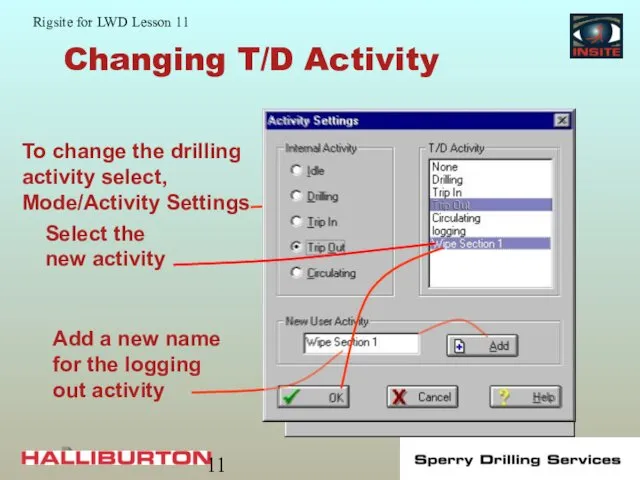
Changing T/D Activity
Changing T/D Activity
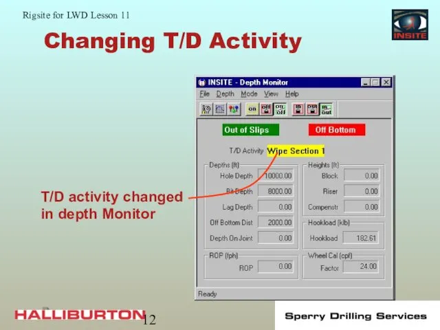
Changing T/D Activity
Changing T/D Activity
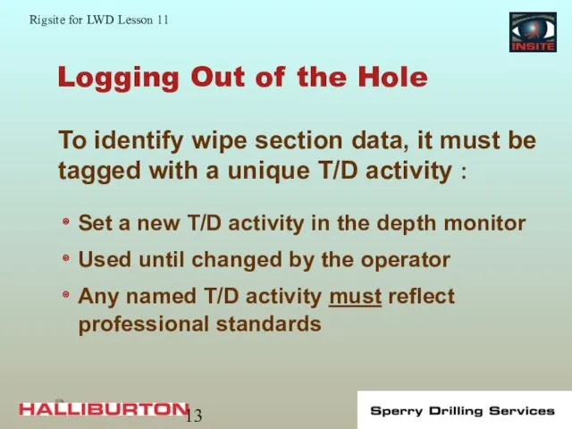
Logging Out of the Hole
Set a new T/D activity in the
Logging Out of the Hole
Set a new T/D activity in the
Surface Sensors
Accurate calibration and reliable operation of surface sensors are critical
Surface Sensors
Accurate calibration and reliable operation of surface sensors are critical
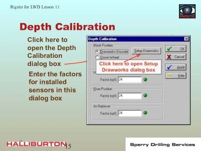
Depth Calibration
Enter the factors for installed sensors in this dialog box
Depth Calibration
Enter the factors for installed sensors in this dialog box
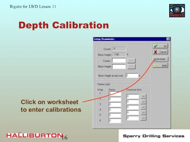
Depth Calibration
Depth Calibration
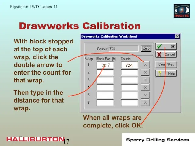
Drawworks Calibration
Drawworks Calibration

Drawworks Calibration
Drawworks Calibration
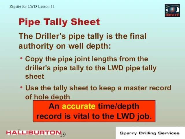
Pipe Tally Sheet
Copy the pipe joint lengths from the driller's pipe
Pipe Tally Sheet
Copy the pipe joint lengths from the driller's pipe
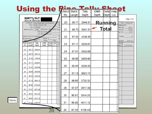
Using the Pipe Tally Sheet
Using the Pipe Tally Sheet
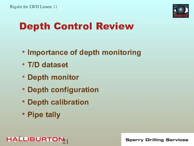
Depth Control Review
Importance of depth monitoring
T/D dataset
Depth monitor
Depth configuration
Depth calibration
Pipe tally
Depth Control Review
Importance of depth monitoring
T/D dataset
Depth monitor
Depth configuration
Depth calibration
Pipe tally
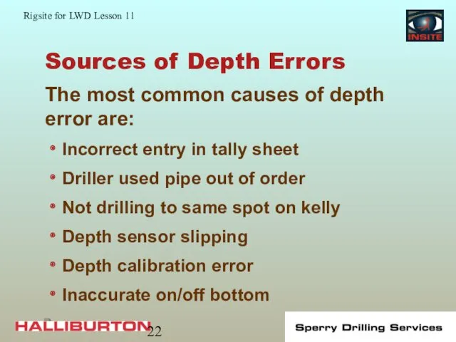
Sources of Depth Errors
Incorrect entry in tally sheet
Driller used pipe out
Sources of Depth Errors
Incorrect entry in tally sheet
Driller used pipe out
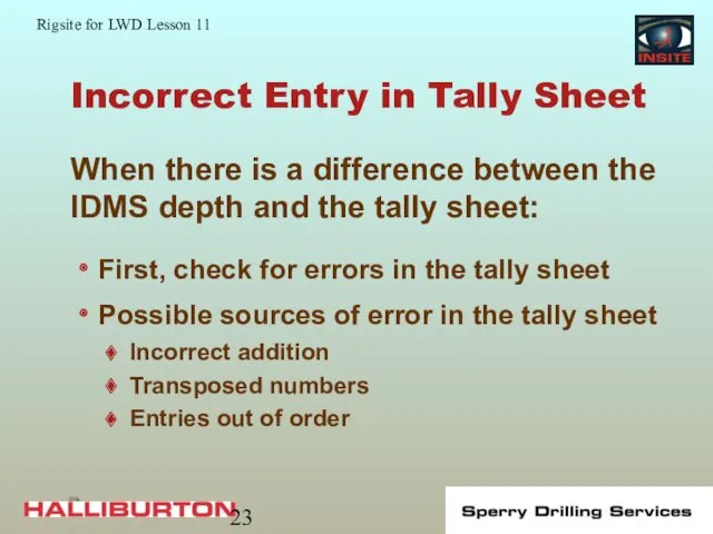
Incorrect Entry in Tally Sheet
First, check for errors in the tally
Incorrect Entry in Tally Sheet
First, check for errors in the tally
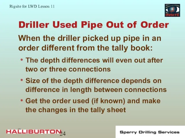
Driller Used Pipe Out of Order
The depth differences will even out
Driller Used Pipe Out of Order
The depth differences will even out
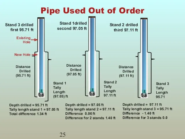
Pipe Used Out of Order
Depth drilled = 95.71 ft
Tally length stand
Pipe Used Out of Order
Depth drilled = 95.71 ft
Tally length stand
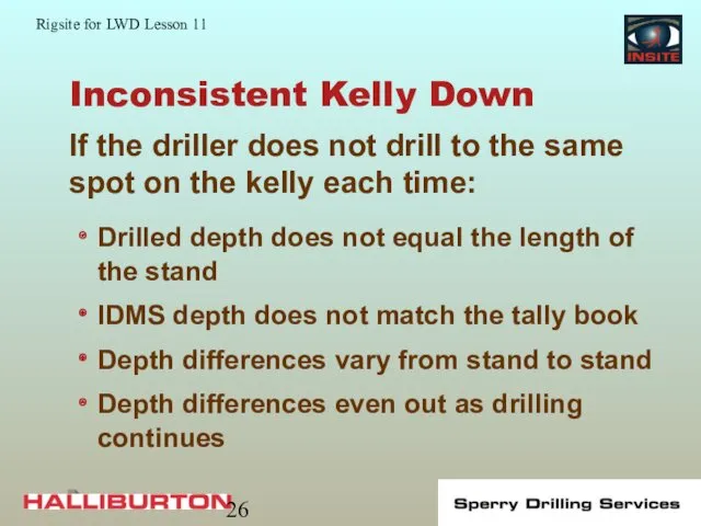
Inconsistent Kelly Down
Drilled depth does not equal the length of the
Inconsistent Kelly Down
Drilled depth does not equal the length of the
Inconsistent Kelly Down
Inconsistent Kelly Down
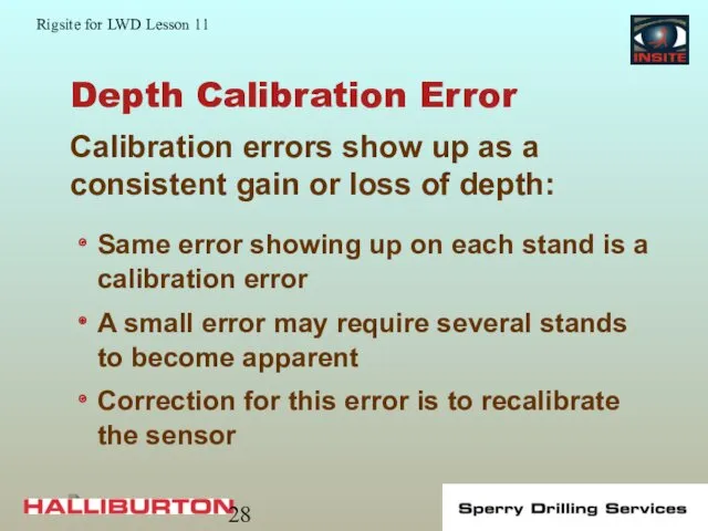
Depth Calibration Error
Same error showing up on each stand is a
Depth Calibration Error
Same error showing up on each stand is a
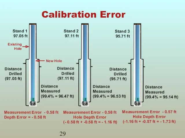
Calibration Error
Measurement Error - 0.58 ft
Depth Error = - 0.58 ft
Measurement
Calibration Error
Measurement Error - 0.58 ft
Depth Error = - 0.58 ft
Measurement
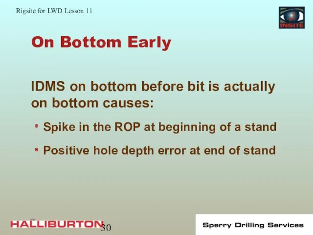
On Bottom Early
Spike in the ROP at beginning of a stand
Positive
On Bottom Early
Spike in the ROP at beginning of a stand
Positive
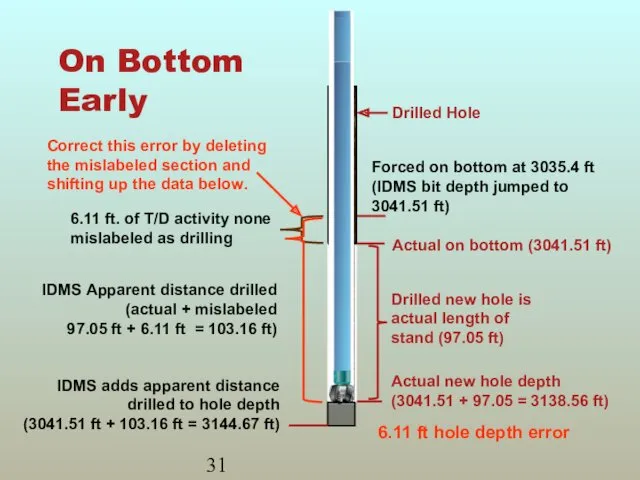
On Bottom Early
6.11 ft hole depth error
On Bottom Early
6.11 ft hole depth error
On Bottom Late
Caused by
Less compression on pipe (less WOB)
Error in
On Bottom Late
Caused by
Less compression on pipe (less WOB)
Error in
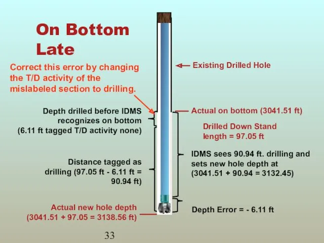
On Bottom Late
On Bottom Late
Crown Wheel Slipping
Most likely to slip during fast movement of the
Crown Wheel Slipping
Most likely to slip during fast movement of the
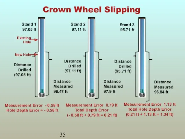
Crown Wheel Slipping
Measurement Error - 0.58 ft
Hole Depth Error = -
Crown Wheel Slipping
Measurement Error - 0.58 ft
Hole Depth Error = -
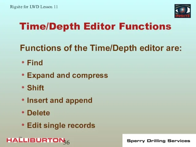
Time/Depth Editor Functions
Find
Expand and compress
Shift
Insert and append
Delete
Edit single records
Functions of the
Time/Depth Editor Functions
Find
Expand and compress
Shift
Insert and append
Delete
Edit single records
Functions of the
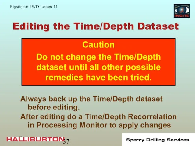
Editing the Time/Depth Dataset
Always back up the Time/Depth dataset before editing.
After
Editing the Time/Depth Dataset
Always back up the Time/Depth dataset before editing.
After
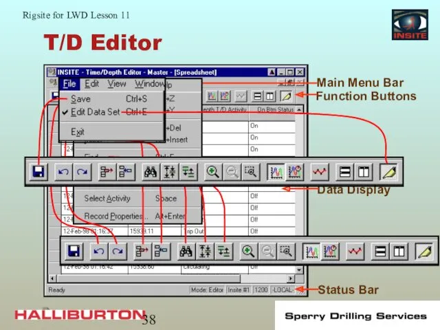
T/D Editor
T/D Editor
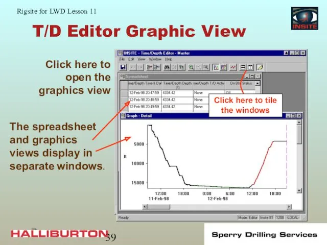
T/D Editor Graphic View
T/D Editor Graphic View
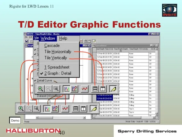
T/D Editor Graphic Functions
T/D Editor Graphic Functions
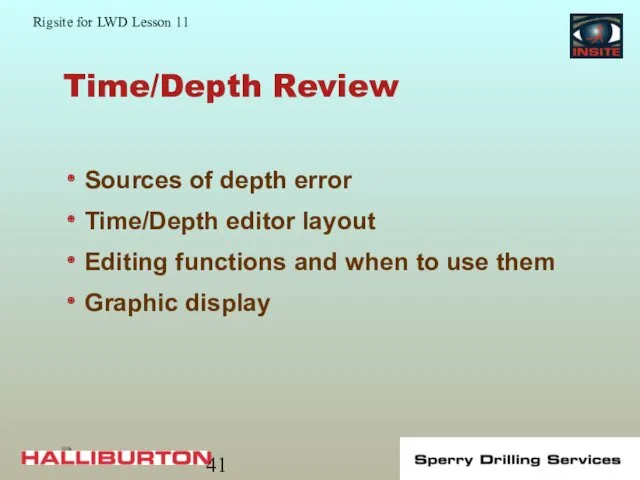
Time/Depth Review
Sources of depth error
Time/Depth editor layout
Editing functions and when to
Time/Depth Review
Sources of depth error
Time/Depth editor layout
Editing functions and when to
Real-Time Data Display
Six applications display real-time data
Real-Time Displays
WellView
Session Log
Real-Time Table
DDU
Real-Time Charts
Real-Time Data Display
Six applications display real-time data
Real-Time Displays
WellView
Session Log
Real-Time Table
DDU
Real-Time Charts
Real-Time Displays
Real-time displays are customized for specific tools or situations:
Built up
Real-Time Displays
Real-time displays are customized for specific tools or situations:
Built up
Real-Time Setup Files
Applications with real-time displays (except DDU and WellView) can
Real-Time Setup Files
Applications with real-time displays (except DDU and WellView) can
DDU Display
The DDU provides the driller with real-time steering information:
Display
DDU Display
The DDU provides the driller with real-time steering information:
Display
Real-Time Table
Real-time tables are customized for specific tools or situations:
Easier to
Real-Time Table
Real-time tables are customized for specific tools or situations:
Easier to
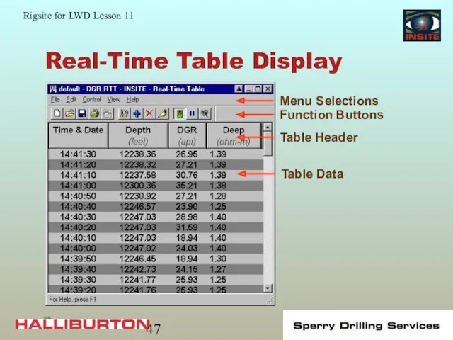
Real-Time Table Display
Real-Time Table Display
Real-Time Charts
Real-time Charts:
X,Y plot or bar chart of selected data
Used
Real-Time Charts
Real-time Charts:
X,Y plot or bar chart of selected data
Used
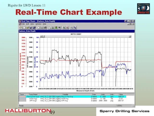
Real-Time Chart Example
Real-Time Chart Example
Session Log
Record of all information received and operations performed by INSITE:
Scrolling
Session Log
Record of all information received and operations performed by INSITE:
Scrolling
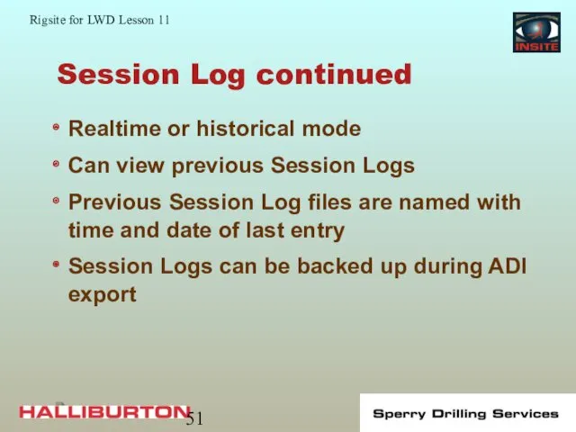
Session Log continued
Realtime or historical mode
Can view previous Session Logs
Previous Session
Session Log continued
Realtime or historical mode
Can view previous Session Logs
Previous Session
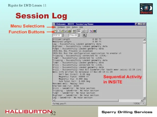
Session Log
Sequential Activity in INSITE
Session Log
Sequential Activity in INSITE
WellView
WellView is a graphic presentation of the drilling track:
Provides a visual
WellView
WellView is a graphic presentation of the drilling track:
Provides a visual
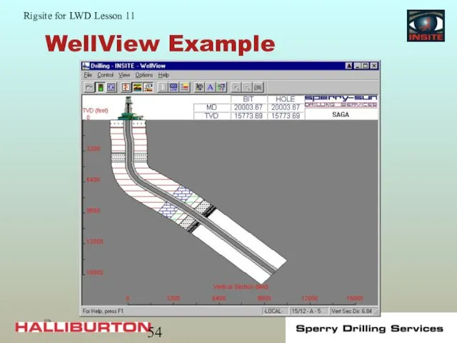
WellView Example
WellView Example
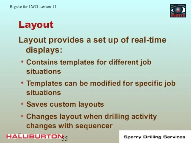
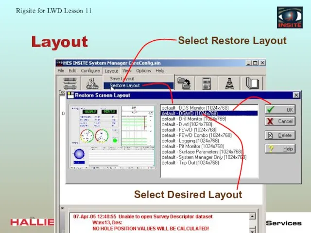
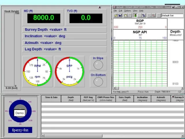
Layout
Layout provides a set up of real-time displays:
Contains templates for different
Layout
Layout provides a set up of real-time displays:
Contains templates for different
Layout
Layout
Layout
Layout
Real-time Display Review
DDU
Tables
Plots
Session log
Layout
Real-time Display Review
DDU
Tables
Plots
Session log
Layout
 Язык HTML
 WSDL - Web Services Description Language
 Канальный уровень функциональной архитектуры телекоммуникационных сетей
 Точні та наближені алгоритми мінімізації числа виконавців при заданих директивних термінах
 Абсолютная и относительная адресация ячеек MS Excel
 Теория и практика информационно-аналитической работы. Семинар
 История создания UNIX-систем. (Занятия 3 и 4)
 Программа Microsoft Excel. Электронные таблицы
 Создание игр в Scratch - 24 - Trex (часть 2)
 Журналистика деген не?
 Типология информационных ресурсов Интернет
 Создателям презентаций. Советы по составлению
 Интерактивная презентация Кроссворд Компьютерные устройства
 Web-страницы. Язык HTML и др
 Мультимедиа технологии
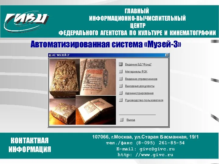 Автоматизированная система Музей-3
 Количество информации
 Розробка Web-сайту кафедри біомедичної інженерії
 Безопасность данных и информационная защита
 Компьютерные вирусы и антивирусные программы
 Знакомство с алгоритмическим языком стрелок
 Основы кибербезопасности. Лекция 4.1. Понятие об источниках и каналах утечки информации; основы технической защиты информации
 Файл. Файловая система
 Основы программирования станков с ЧПУ и программоносители
 Управление в автоматизированном производстве (01)
 Знакомство с библиотекой
 Простейшие программы
 Оперативно-информационный комплекс СК-2007 для диспетчерского управления электроэнергетическими системами. Монитор Электрик