- The Verilog Language

Содержание
- 2. The Verilog Language Originally a modeling language for a very efficient event-driven digital logic simulator Later
- 3. Structural Modeling When Verilog was first developed (1984) most logic simulators operated on netlists Netlist: list
- 4. Behavioral Modeling A much easier way to write testbenches Also good for more abstract models of
- 5. How Verilog Is Used Virtually every ASIC is designed using either Verilog or VHDL (a similar
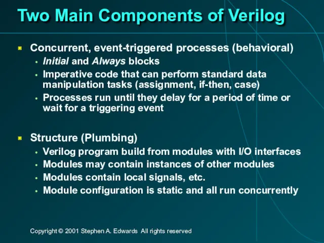
- 6. Two Main Components of Verilog Concurrent, event-triggered processes (behavioral) Initial and Always blocks Imperative code that
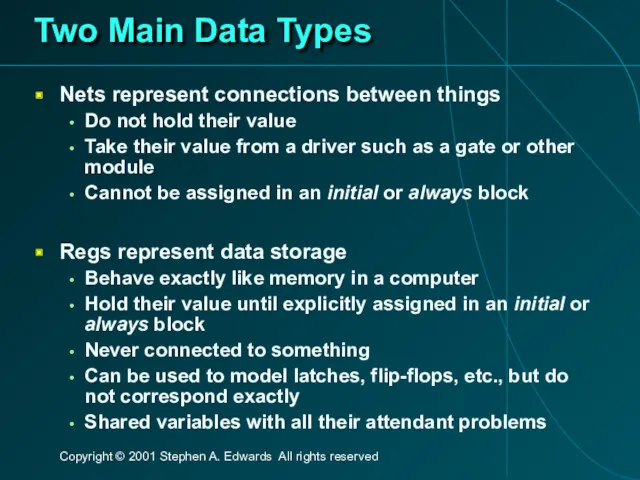
- 7. Two Main Data Types Nets represent connections between things Do not hold their value Take their
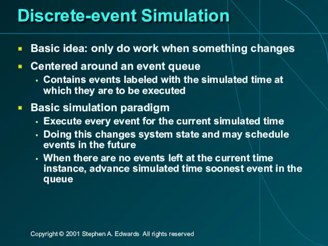
- 8. Discrete-event Simulation Basic idea: only do work when something changes Centered around an event queue Contains
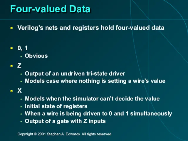
- 9. Four-valued Data Verilog’s nets and registers hold four-valued data 0, 1 Obvious Z Output of an
- 10. Four-valued Logic Logical operators work on three-valued logic 0 1 X Z 0 0 0 0
- 11. Structural Modeling
- 12. Nets and Registers Wires and registers can be bits, vectors, and arrays wire a; // Simple
- 13. Modules and Instances Basic structure of a Verilog module: module mymod(output1, output2, … input1, input2); output
- 14. Instantiating a Module Instances of module mymod(y, a, b); look like mymod mm1(y1, a1, b1); //
- 15. Gate-level Primitives Verilog provides the following: and nand logical AND/NAND or nor logical OR/NOR xor xnor
- 16. Delays on Primitive Instances Instances of primitives may include delays buf b1(a, b); // Zero delay
- 17. User-Defined Primitives Way to define gates and sequential elements using a truth table Often simulate faster
- 18. A Carry Primitive primitive carry(out, a, b, c); output out; input a, b, c; table 00?
- 19. A Sequential Primitive Primitive dff( q, clk, data); output q; reg q; input clk, data; table
- 20. Continuous Assignment Another way to describe combinational function Convenient for logical or datapath specifications wire [8:0]
- 21. Behavioral Modeling
- 22. Initial and Always Blocks Basic components for behavioral modeling initial begin … imperative statements … end
- 23. Initial and Always Run until they encounter a delay initial begin #10 a = 1; b
- 24. Procedural Assignment Inside an initial or always block: sum = a + b + cin; Just
- 25. Imperative Statements if (select == 1) y = a; else y = b; case (op) 2’b00:
- 26. For Loops A increasing sequence of values on an output reg [3:0] i, output; for (
- 27. While Loops A increasing sequence of values on an output reg [3:0] i, output; i =
- 28. Modeling A Flip-Flop With Always Very basic: an edge-sensitive flip-flop reg q; always @(posedge clk) q
- 29. Blocking vs. Nonblocking Verilog has two types of procedural assignment Fundamental problem: In a synchronous system,
- 30. A Flawed Shift Register This doesn’t work as you’d expect: reg d1, d2, d3, d4; always
- 31. Non-blocking Assignments This version does work: reg d1, d2, d3, d4; always @(posedge clk) d2 always
- 32. Nonblocking Can Behave Oddly A sequence of nonblocking assignments don’t communicate a = 1; b =
- 33. Nonblocking Looks Like Latches RHS of nonblocking taken from latches RHS of blocking taken from wires
- 34. Building Behavioral Models
- 35. Modeling FSMs Behaviorally There are many ways to do it: Define the next-state logic combinationally and
- 36. FSM with Combinational Logic module FSM(o, a, b, reset); output o; reg o; input a, b,
- 37. FSM with Combinational Logic module FSM(o, a, b, reset); … always @(posedge clk or reset) if
- 38. FSM from Combinational Logic always @(a or b or state) case (state) 2’b00: begin nextState =
- 39. FSM from a Single Always Block module FSM(o, a, b); output o; reg o; input a,
- 40. Simulating Verilog
- 41. How Are Simulators Used? Testbench generates stimulus and checks response Coupled to model of the system
- 42. Writing Testbenches module test; reg a, b, sel; mux m(y, a, b, sel); initial begin $monitor($time,,
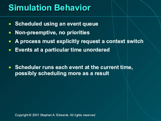
- 43. Simulation Behavior Scheduled using an event queue Non-preemptive, no priorities A process must explicitly request a
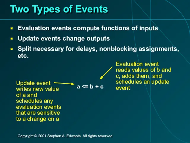
- 44. Two Types of Events Evaluation events compute functions of inputs Update events change outputs Split necessary
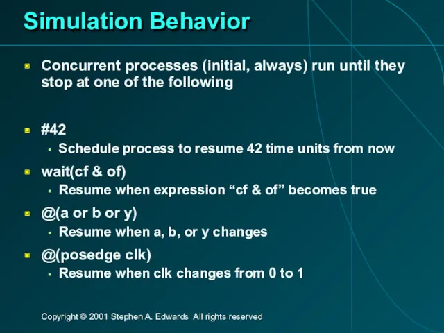
- 45. Simulation Behavior Concurrent processes (initial, always) run until they stop at one of the following #42
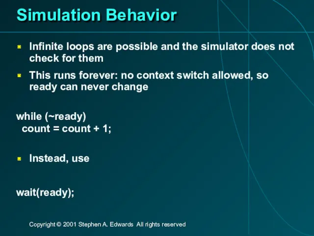
- 46. Simulation Behavior Infinite loops are possible and the simulator does not check for them This runs
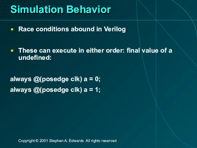
- 47. Simulation Behavior Race conditions abound in Verilog These can execute in either order: final value of
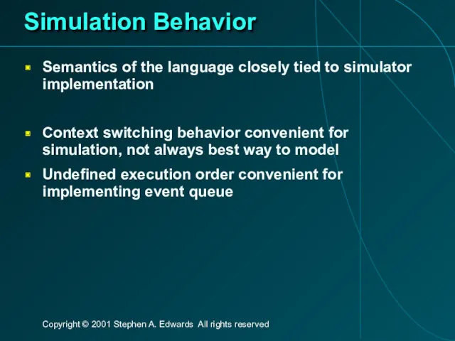
- 48. Simulation Behavior Semantics of the language closely tied to simulator implementation Context switching behavior convenient for
- 49. Verilog and Logic Synthesis
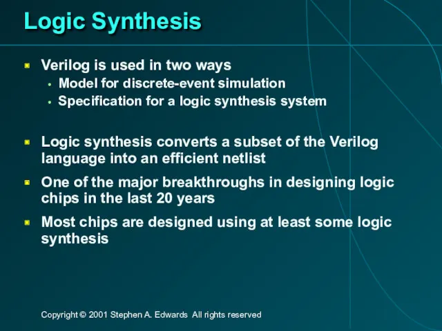
- 50. Logic Synthesis Verilog is used in two ways Model for discrete-event simulation Specification for a logic
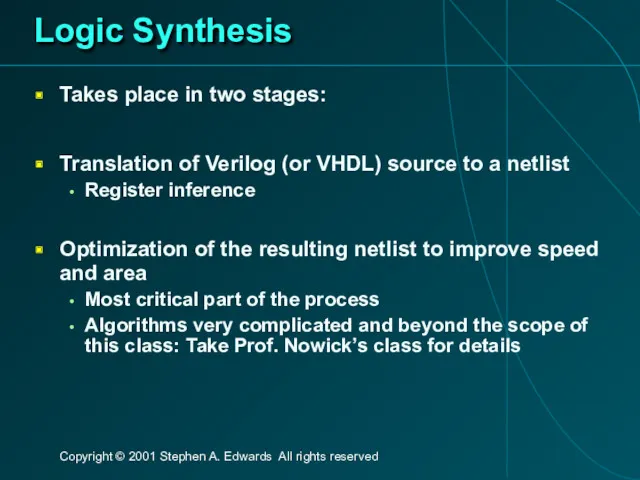
- 51. Logic Synthesis Takes place in two stages: Translation of Verilog (or VHDL) source to a netlist
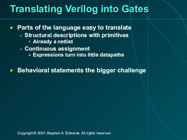
- 52. Translating Verilog into Gates Parts of the language easy to translate Structural descriptions with primitives Already
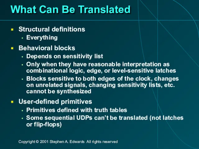
- 53. What Can Be Translated Structural definitions Everything Behavioral blocks Depends on sensitivity list Only when they
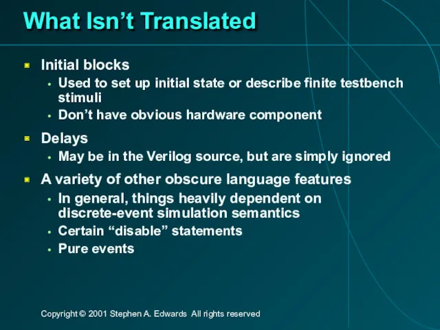
- 54. What Isn’t Translated Initial blocks Used to set up initial state or describe finite testbench stimuli
- 55. Register Inference The main trick reg does not always equal latch Rule: Combinational if outputs always
- 56. Register Inference Combinational: reg y; always @(a or b or sel) if (sel) y = a;
- 57. Register Inference A common mistake is not completely specifying a case statement This implies a latch:
- 58. Register Inference The solution is to always have a default case always @(a or b) case
- 59. Inferring Latches with Reset Latches and Flip-flops often have reset inputs Can be synchronous or asynchronous
- 60. Simulation-synthesis Mismatches Many possible sources of conflict Synthesis ignores delays (e.g., #10), but simulation behavior can
- 62. Скачать презентацию
The Verilog Language
Originally a modeling language for a very efficient event-driven
The Verilog Language
Originally a modeling language for a very efficient event-driven
Structural Modeling
When Verilog was first developed (1984) most logic simulators operated
Structural Modeling
When Verilog was first developed (1984) most logic simulators operated
Behavioral Modeling
A much easier way to write testbenches
Also good for more
Behavioral Modeling
A much easier way to write testbenches
Also good for more
How Verilog Is Used
Virtually every ASIC is designed using either Verilog
How Verilog Is Used
Virtually every ASIC is designed using either Verilog
Two Main Components of Verilog
Concurrent, event-triggered processes (behavioral)
Initial and Always blocks
Imperative
Two Main Components of Verilog
Concurrent, event-triggered processes (behavioral)
Initial and Always blocks
Imperative
Two Main Data Types
Nets represent connections between things
Do not hold their
Two Main Data Types
Nets represent connections between things
Do not hold their
Discrete-event Simulation
Basic idea: only do work when something changes
Centered around an
Discrete-event Simulation
Basic idea: only do work when something changes
Centered around an
Four-valued Data
Verilog’s nets and registers hold four-valued data
0, 1
Obvious
Z
Output of an
Four-valued Data
Verilog’s nets and registers hold four-valued data
0, 1
Obvious
Z
Output of an
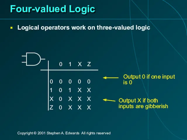
Four-valued Logic
Logical operators work on three-valued logic
0 1 X Z
0 0 0 0 0
1 0 1 X X
X 0 X X X
Z 0 X X X
Output 0 if one input
Four-valued Logic
Logical operators work on three-valued logic
0 1 X Z
0 0 0 0 0
1 0 1 X X
X 0 X X X
Z 0 X X X
Output 0 if one input
Structural Modeling
Structural Modeling
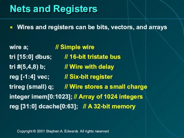
Nets and Registers
Wires and registers can be bits, vectors, and arrays
wire
Nets and Registers
Wires and registers can be bits, vectors, and arrays
wire
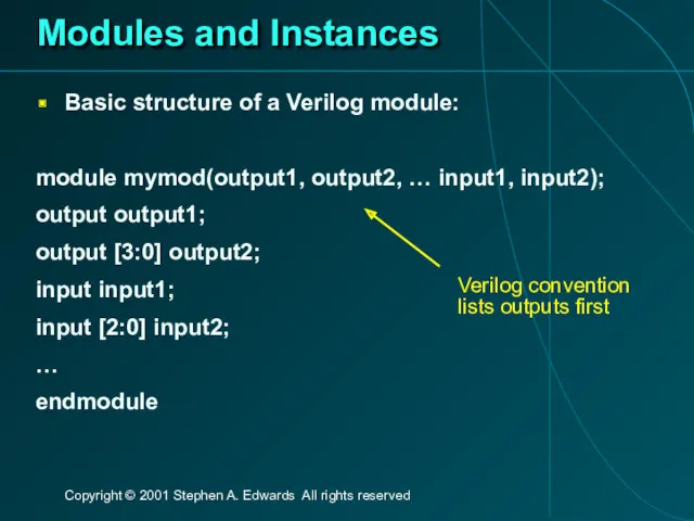
Modules and Instances
Basic structure of a Verilog module:
module mymod(output1, output2, …
Modules and Instances
Basic structure of a Verilog module:
module mymod(output1, output2, …
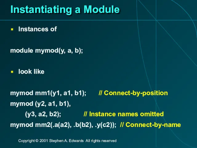
Instantiating a Module
Instances of
module mymod(y, a, b);
look like
mymod mm1(y1, a1, b1); //
Instantiating a Module
Instances of
module mymod(y, a, b);
look like
mymod mm1(y1, a1, b1); //
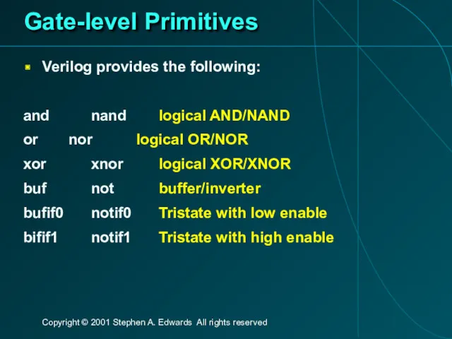
Gate-level Primitives
Verilog provides the following:
and nand logical AND/NAND
or nor logical OR/NOR
xor xnor logical XOR/XNOR
buf not buffer/inverter
bufif0 notif0 Tristate with low enable
bifif1 notif1 Tristate
Gate-level Primitives
Verilog provides the following:
and nand logical AND/NAND
or nor logical OR/NOR
xor xnor logical XOR/XNOR
buf not buffer/inverter
bufif0 notif0 Tristate with low enable
bifif1 notif1 Tristate
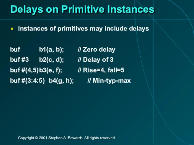
Delays on Primitive Instances
Instances of primitives may include delays
buf b1(a, b); // Zero
Delays on Primitive Instances
Instances of primitives may include delays
buf b1(a, b); // Zero
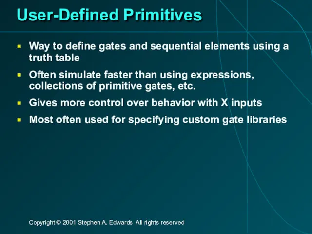
User-Defined Primitives
Way to define gates and sequential elements using a truth
User-Defined Primitives
Way to define gates and sequential elements using a truth
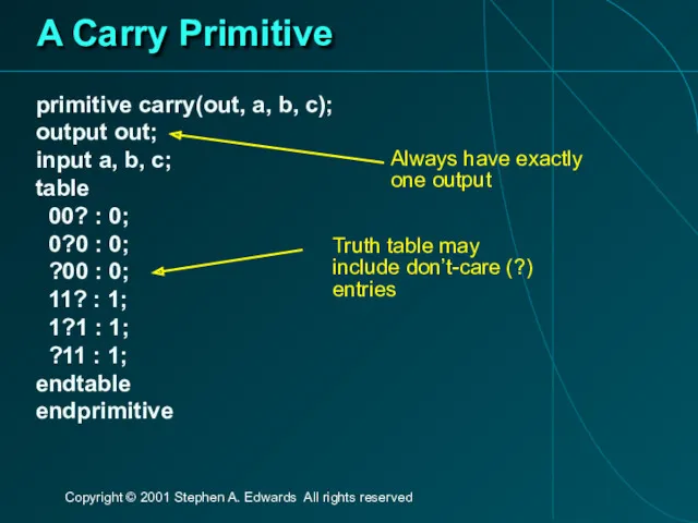
A Carry Primitive
primitive carry(out, a, b, c);
output out;
input a, b, c;
table
A Carry Primitive
primitive carry(out, a, b, c);
output out;
input a, b, c;
table
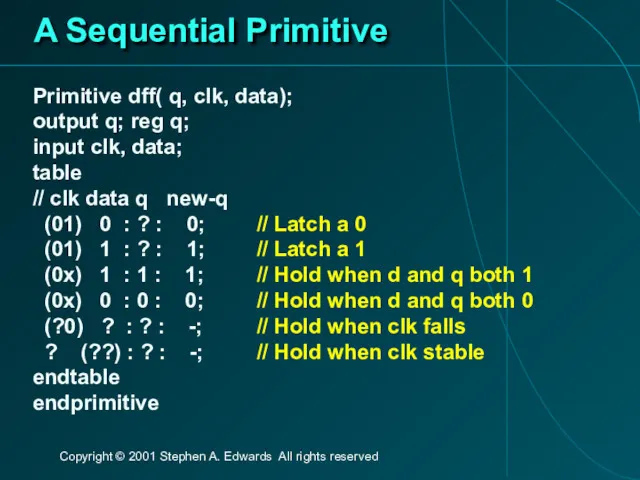
A Sequential Primitive
Primitive dff( q, clk, data);
output q; reg q;
input clk,
A Sequential Primitive
Primitive dff( q, clk, data);
output q; reg q;
input clk,
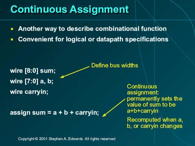
Continuous Assignment
Another way to describe combinational function
Convenient for logical or datapath
Continuous Assignment
Another way to describe combinational function
Convenient for logical or datapath
Behavioral Modeling
Behavioral Modeling
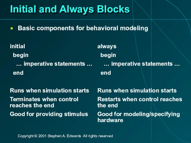
Initial and Always Blocks
Basic components for behavioral modeling
initial
begin
… imperative
Initial and Always Blocks
Basic components for behavioral modeling
initial
begin
… imperative
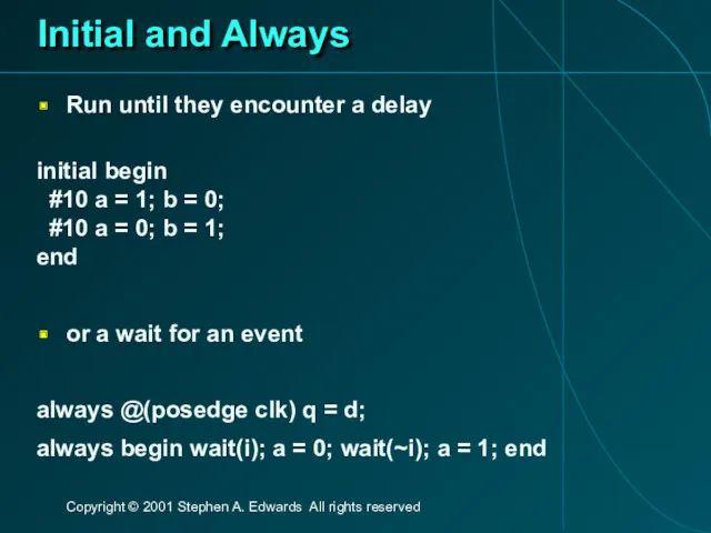
Initial and Always
Run until they encounter a delay
initial begin
#10 a
Initial and Always
Run until they encounter a delay
initial begin
#10 a
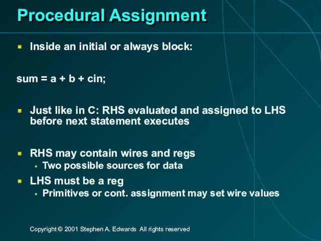
Procedural Assignment
Inside an initial or always block:
sum = a + b
Procedural Assignment
Inside an initial or always block:
sum = a + b
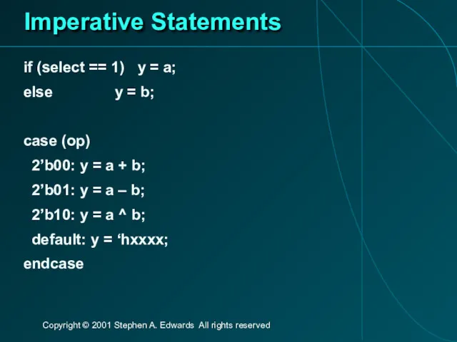
Imperative Statements
if (select == 1) y = a;
else y = b;
case (op)
2’b00:
Imperative Statements
if (select == 1) y = a;
else y = b;
case (op)
2’b00:
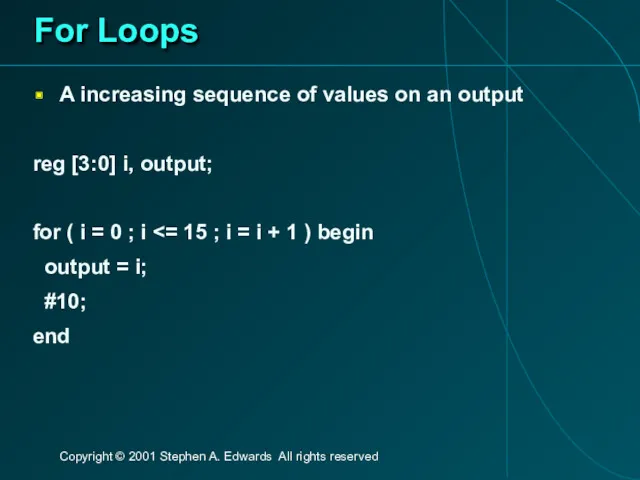
For Loops
A increasing sequence of values on an output
reg [3:0] i,
For Loops
A increasing sequence of values on an output
reg [3:0] i,
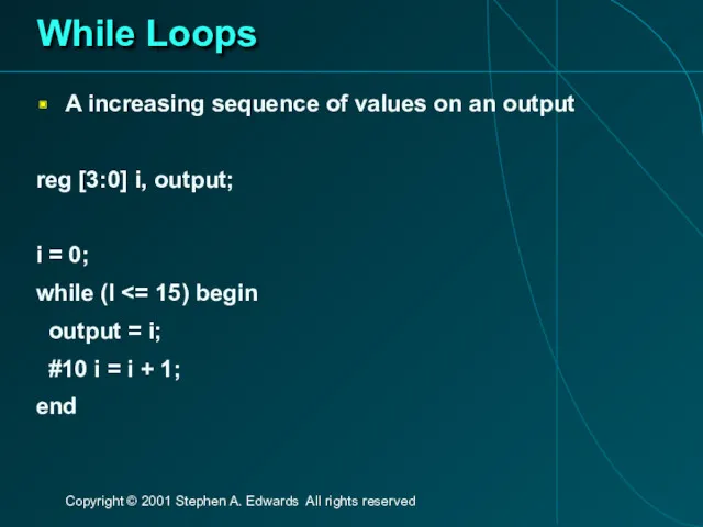
While Loops
A increasing sequence of values on an output
reg [3:0] i,
While Loops
A increasing sequence of values on an output
reg [3:0] i,
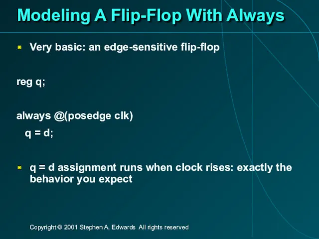
Modeling A Flip-Flop With Always
Very basic: an edge-sensitive flip-flop
reg q;
always @(posedge
Modeling A Flip-Flop With Always
Very basic: an edge-sensitive flip-flop
reg q;
always @(posedge
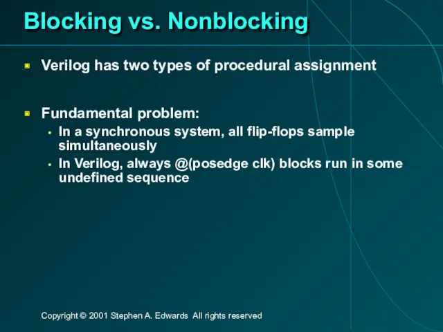
Blocking vs. Nonblocking
Verilog has two types of procedural assignment
Fundamental problem:
In a
Blocking vs. Nonblocking
Verilog has two types of procedural assignment
Fundamental problem:
In a
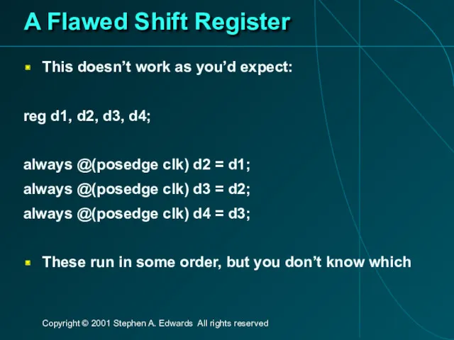
A Flawed Shift Register
This doesn’t work as you’d expect:
reg d1, d2,
A Flawed Shift Register
This doesn’t work as you’d expect:
reg d1, d2,
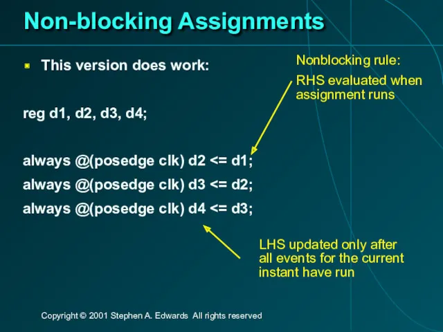
Non-blocking Assignments
This version does work:
reg d1, d2, d3, d4;
always @(posedge clk)
Non-blocking Assignments
This version does work:
reg d1, d2, d3, d4;
always @(posedge clk)
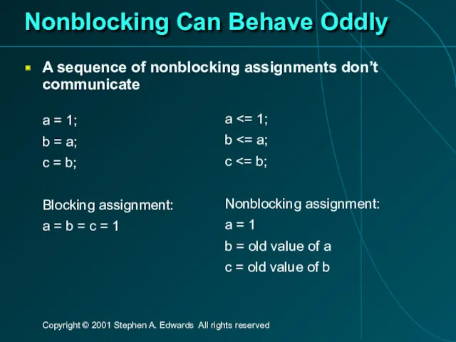
Nonblocking Can Behave Oddly
A sequence of nonblocking assignments don’t communicate
a =
Nonblocking Can Behave Oddly
A sequence of nonblocking assignments don’t communicate
a =
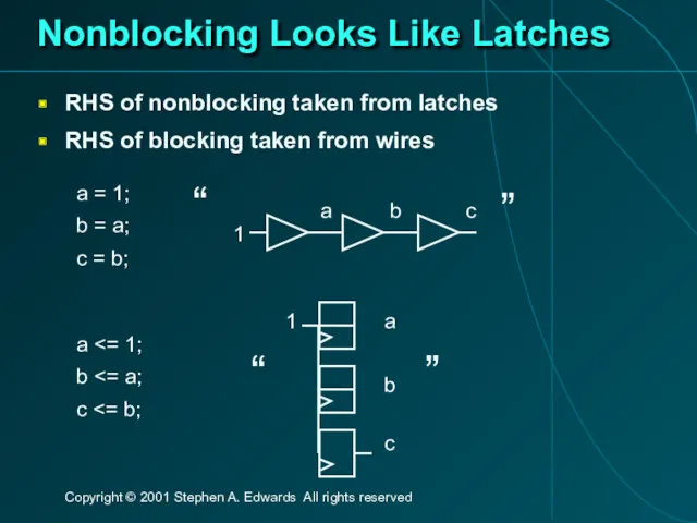
Nonblocking Looks Like Latches
RHS of nonblocking taken from latches
RHS of blocking
Nonblocking Looks Like Latches
RHS of nonblocking taken from latches
RHS of blocking

Building Behavioral Models
Building Behavioral Models
Modeling FSMs Behaviorally
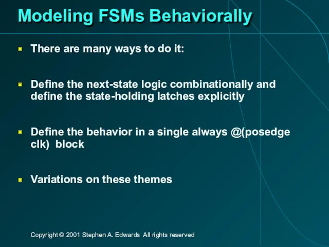
There are many ways to do it:
Define the next-state
Modeling FSMs Behaviorally
There are many ways to do it:
Define the next-state
FSM with Combinational Logic
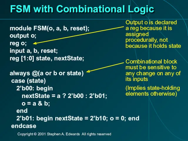
module FSM(o, a, b, reset);
output o;
reg o;
input a,
FSM with Combinational Logic
module FSM(o, a, b, reset);
output o;
reg o;
input a,
FSM with Combinational Logic
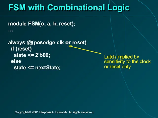
module FSM(o, a, b, reset);
…
always @(posedge clk or
FSM with Combinational Logic
module FSM(o, a, b, reset);
…
always @(posedge clk or
FSM from Combinational Logic
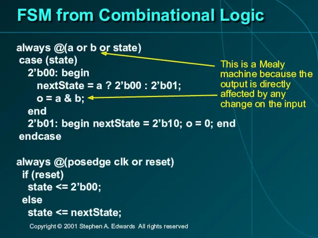
always @(a or b or state)
case (state)
FSM from Combinational Logic
always @(a or b or state)
case (state)
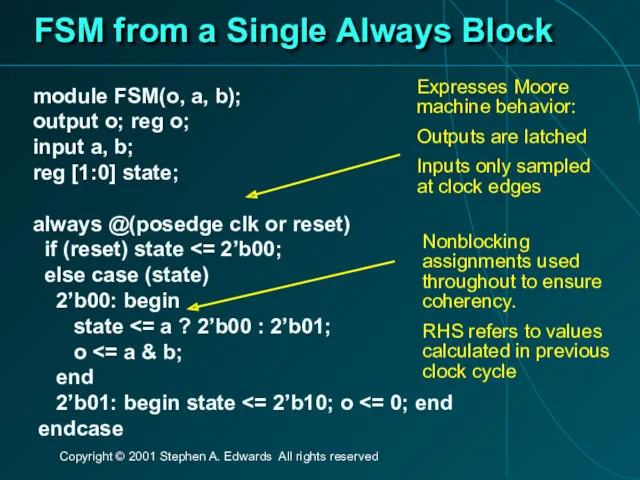
FSM from a Single Always Block
module FSM(o, a, b);
output o; reg
FSM from a Single Always Block
module FSM(o, a, b);
output o; reg
Simulating Verilog
Simulating Verilog
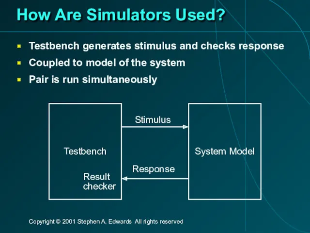
How Are Simulators Used?
Testbench generates stimulus and checks response
Coupled to model
How Are Simulators Used?
Testbench generates stimulus and checks response
Coupled to model
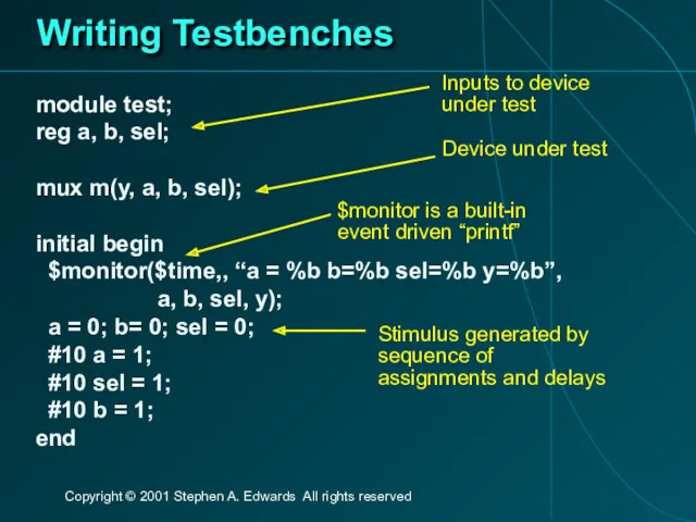
Writing Testbenches
module test;
reg a, b, sel;
mux m(y, a, b, sel);
initial begin
Writing Testbenches
module test;
reg a, b, sel;
mux m(y, a, b, sel);
initial begin
Simulation Behavior
Scheduled using an event queue
Non-preemptive, no priorities
A process must explicitly
Simulation Behavior
Scheduled using an event queue
Non-preemptive, no priorities
A process must explicitly
Two Types of Events
Evaluation events compute functions of inputs
Update events change
Two Types of Events
Evaluation events compute functions of inputs
Update events change
Simulation Behavior
Concurrent processes (initial, always) run until they stop at one
Simulation Behavior
Concurrent processes (initial, always) run until they stop at one
Simulation Behavior
Infinite loops are possible and the simulator does not check
Simulation Behavior
Infinite loops are possible and the simulator does not check
Simulation Behavior
Race conditions abound in Verilog
These can execute in either order:
Simulation Behavior
Race conditions abound in Verilog
These can execute in either order:
Simulation Behavior
Semantics of the language closely tied to simulator implementation
Context switching
Simulation Behavior
Semantics of the language closely tied to simulator implementation
Context switching
Verilog and Logic Synthesis
Verilog and Logic Synthesis
Logic Synthesis
Verilog is used in two ways
Model for discrete-event simulation
Specification for
Logic Synthesis
Verilog is used in two ways
Model for discrete-event simulation
Specification for
Logic Synthesis
Takes place in two stages:
Translation of Verilog (or VHDL) source
Logic Synthesis
Takes place in two stages:
Translation of Verilog (or VHDL) source
Translating Verilog into Gates
Parts of the language easy to translate
Structural descriptions
Translating Verilog into Gates
Parts of the language easy to translate
Structural descriptions
What Can Be Translated
Structural definitions
Everything
Behavioral blocks
Depends on sensitivity list
Only when they
What Can Be Translated
Structural definitions
Everything
Behavioral blocks
Depends on sensitivity list
Only when they
What Isn’t Translated
Initial blocks
Used to set up initial state or describe
What Isn’t Translated
Initial blocks
Used to set up initial state or describe
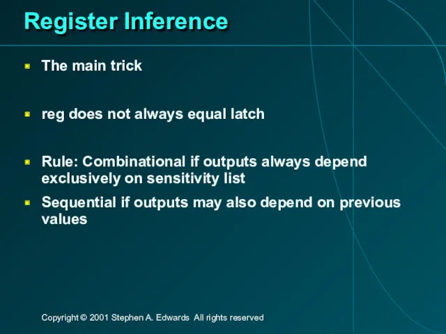
Register Inference
The main trick
reg does not always equal latch
Rule: Combinational if
Register Inference
The main trick
reg does not always equal latch
Rule: Combinational if
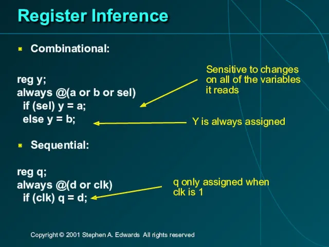
Register Inference
Combinational:
reg y;
always @(a or b or sel)
if (sel) y
Register Inference
Combinational:
reg y;
always @(a or b or sel)
if (sel) y
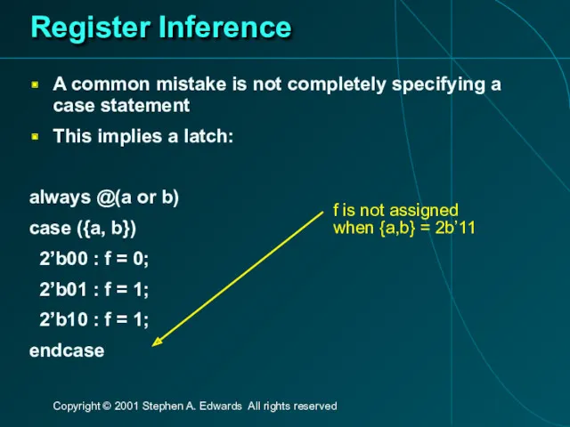
Register Inference
A common mistake is not completely specifying a case statement
This
Register Inference
A common mistake is not completely specifying a case statement
This
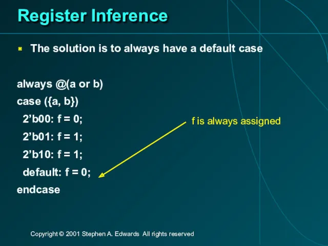
Register Inference
The solution is to always have a default case
always @(a
Register Inference
The solution is to always have a default case
always @(a
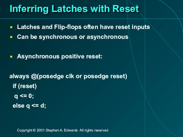
Inferring Latches with Reset
Latches and Flip-flops often have reset inputs
Can be
Inferring Latches with Reset
Latches and Flip-flops often have reset inputs
Can be
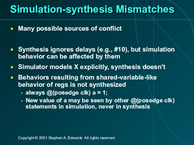
Simulation-synthesis Mismatches
Many possible sources of conflict
Synthesis ignores delays (e.g., #10), but
Simulation-synthesis Mismatches
Many possible sources of conflict
Synthesis ignores delays (e.g., #10), but
 История ЭВМ
 Урок в 5 классе Метод координат
 Коммутация каналов, коммутация пакетов. Постоянная и динамическая коммутация сети
 Разработка методики тестирования crm-систем для компании-разработчика программного обеспечения
 Глобальная сеть Интернет
 Компьютерная графика (Autodesk 3ds max). Создание и работа с примитивами. Управление объектами. (Лекция 2.1)
 PostgreSQL. День 4
 Об’єкти, функції і події в JavaScript. (Лекція 7)
 Анализ типов заголовков и интервью в современных СМИ
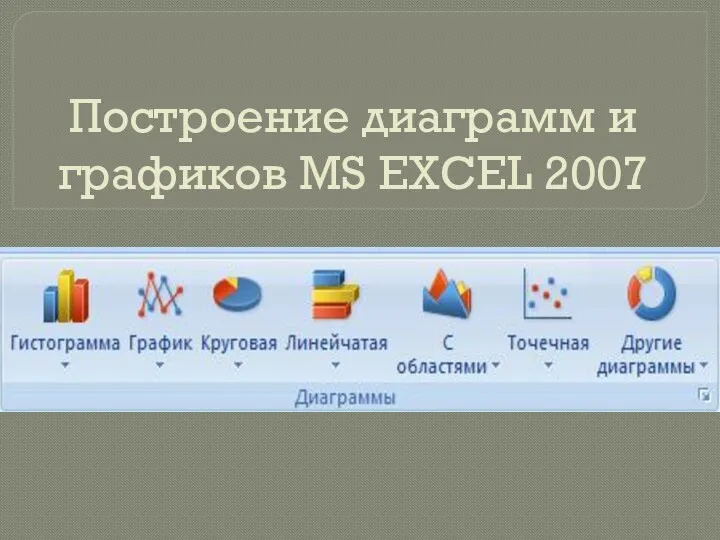 Презентаци. Построение диаграмм в MS Excel 2007
 Файловая система. Функции API для работы с файлами. Занятие 04, 05
 Сеть Ethernet. Построение коммутируемой сети
 Интернет вещей. Технология IOT
 Методологии разработки ПО
 Информационный комитет Студенческого совета СПбГУ
 Виртуальная реальность
 Итоговый проект по информатике Операционная система. Принципы и задачи
 Криптографические методы защиты информации
 Сбор и подготовка данных
 Требования к структуре и формату презентации инженерного кейса. Международный инженерный чемпионат CASE-IN (ЛС)
 Introduction to Google Maps
 Виды вторичного текста. Компрессия
 Нейронная сеть — математическая модель
 Программирование разветвляющихся алгоритмов. Начала программирования
 Данная и новая информация текста
 Итоговая работа по модулю 4: Интернет-магазин
 Основы языка HTML
 Розподілені системи обробки інформації