- Index of Refraction

Содержание
- 2. In uniform isotropic linear media, the wave equation is: They are satisfied by plane wave ψ=A
- 3. We can define the index of refraction as Most media are nonmagnetic and have a magnetic
- 4. Let the electric field of optical wave in an atom be E=E0e-iωt the electron obeys the
- 5. The solution is The induced dipole moment is α is atomic polarizability The dielectric constant of
- 6. If the second term is small enough then The dielectric constant of the medium is given
- 7. The complex refractive index is Normalized plot of n-1 and k versus ω−ω0 at ω ~ω0
- 8. For more than one resonance frequencies for each atom, Classical Electron Model ( Drude model) If
- 9. By definition, We can easily get: Relation Between Dielectric Constant and Refractive Index
- 10. Real and imaginary part of the index of refraction of GaN vs. energy; An Example to
- 11. The real part and imaginary part of the complex dielectric function ε (ω) are not independent.
- 12. Typical experimental setup ( 1) halogen lamp; (2) mono-chromator; (3) chopper; (4) filter; (5) polarizer (get
- 13. Snell Law become: Reflection of p-polarized light Reflection coefficient: In this case, n1=1, and n2=nr+i n
- 14. Results Based on Reflection Measurement FIG. 2. Measured refractive indices at 300 K vs. photon energy
- 15. Use AFM to Determine the Refractive Index Profiles of Optical Fibers Fiber samples were Cleaved and
- 16. The optical lever operates by reflecting a laser beam off the cantilever. Angular deflection of the
- 17. Result
- 18. For θ=0, input wave function a e iφ , tm=aTT’R’2m-1 e i(φ-(2m-1)δ ) (m=1,2…) δ=2πdn/λ The
- 19. Result Based on Transmission Measurement
- 20. Application In our lab., we have a simple system to measure the thickness of epitaxial GaN
- 21. n(λm)=m λm/2d Thickness Measurement Steps to calculate thickness Get peak position λm d=(λm λm-1)/2/[λm-1 n(λm) −
- 23. Скачать презентацию
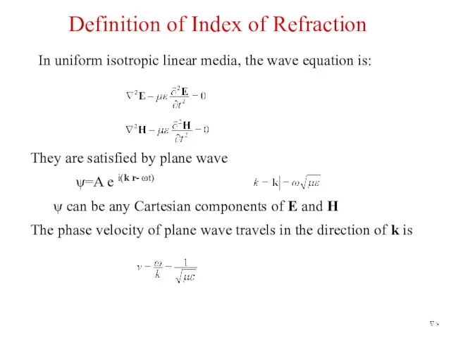
In uniform isotropic linear media, the wave equation is:
They are satisfied
In uniform isotropic linear media, the wave equation is:
They are satisfied
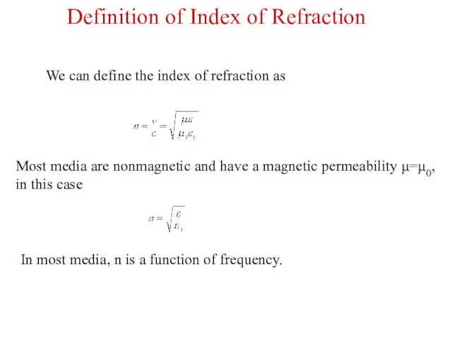
We can define the index of refraction as
Most media are nonmagnetic
We can define the index of refraction as
Most media are nonmagnetic
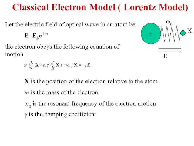
Let the electric field of optical wave in an atom be
E=E0e-iωt
the
Let the electric field of optical wave in an atom be
E=E0e-iωt
the
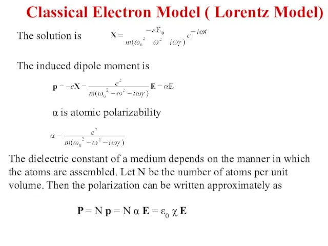
The solution is
The induced dipole moment is
α is atomic polarizability
The dielectric
The solution is
The induced dipole moment is
α is atomic polarizability
The dielectric
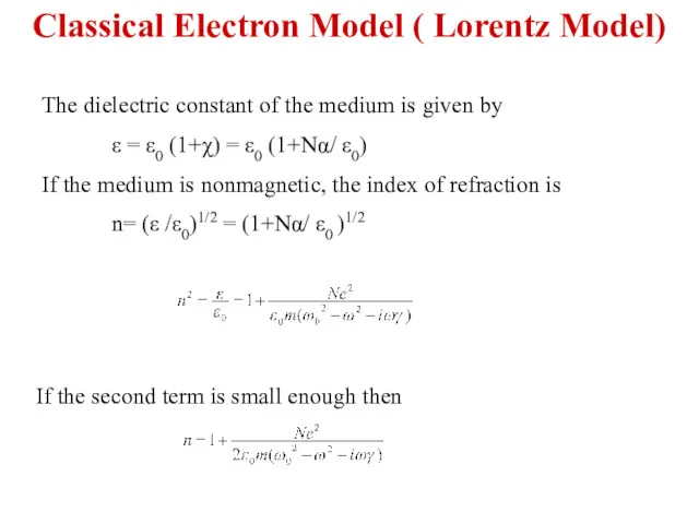
If the second term is small enough then
The dielectric constant of
If the second term is small enough then
The dielectric constant of
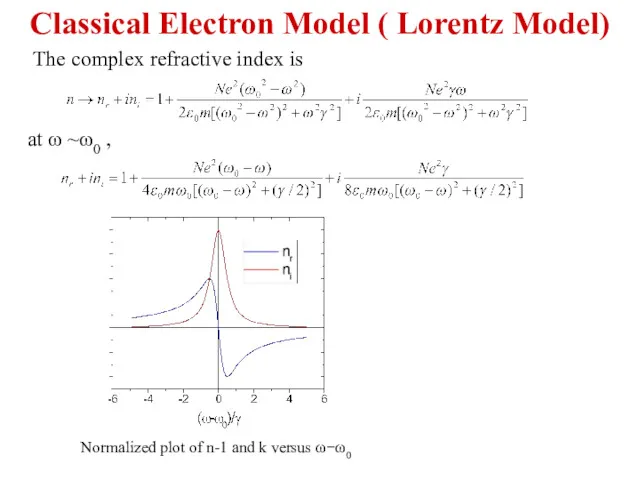
The complex refractive index is
Normalized plot of n-1 and k versus
The complex refractive index is
Normalized plot of n-1 and k versus
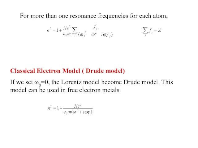
For more than one resonance frequencies for each atom,
Classical Electron Model
For more than one resonance frequencies for each atom,
Classical Electron Model
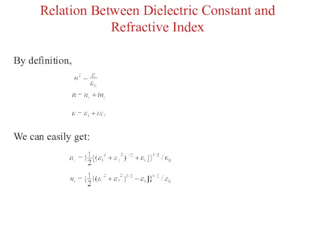
By definition,
We can easily get:
Relation Between Dielectric Constant and Refractive Index
By definition,
We can easily get:
Relation Between Dielectric Constant and Refractive Index
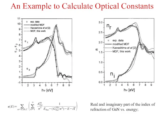
Real and imaginary part of the index of refraction of GaN
Real and imaginary part of the index of refraction of GaN
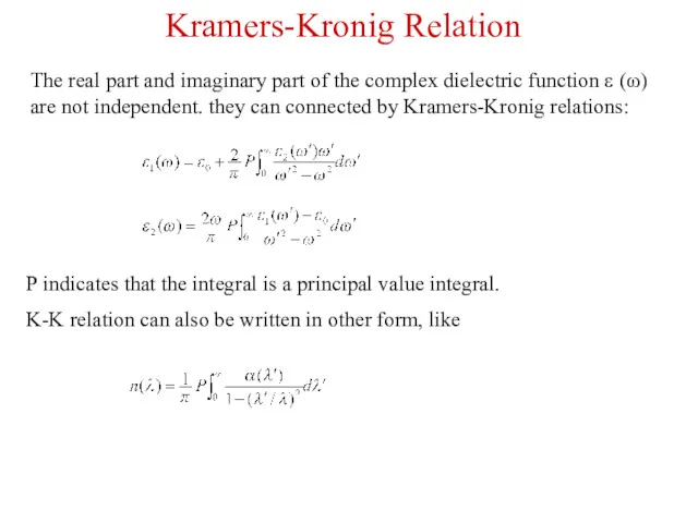
The real part and imaginary part of the complex dielectric function
The real part and imaginary part of the complex dielectric function
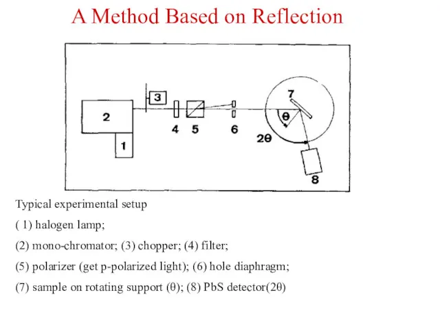
Typical experimental setup
( 1) halogen lamp;
(2) mono-chromator; (3) chopper; (4)
Typical experimental setup
( 1) halogen lamp;
(2) mono-chromator; (3) chopper; (4)
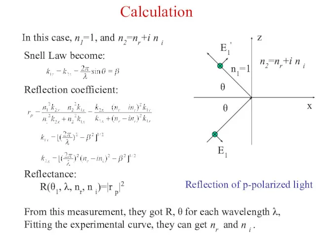
Snell Law become:
Reflection of p-polarized light
Reflection coefficient:
In this case, n1=1, and
Snell Law become:
Reflection of p-polarized light
Reflection coefficient:
In this case, n1=1, and
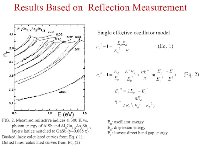
Results Based on Reflection Measurement
FIG. 2. Measured refractive indices at 300
Results Based on Reflection Measurement
FIG. 2. Measured refractive indices at 300
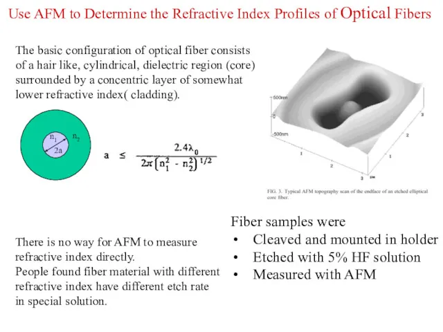
Use AFM to Determine the Refractive Index Profiles of Optical Fibers
Fiber
Use AFM to Determine the Refractive Index Profiles of Optical Fibers
Fiber
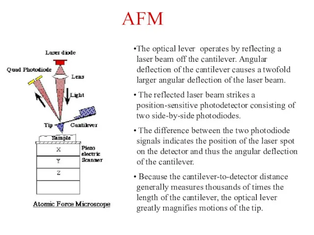
The optical lever operates by reflecting a laser beam off the
The optical lever operates by reflecting a laser beam off the
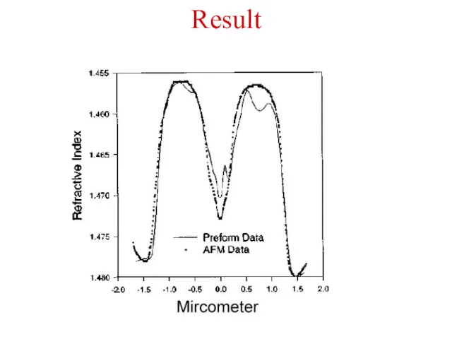
Result
Result
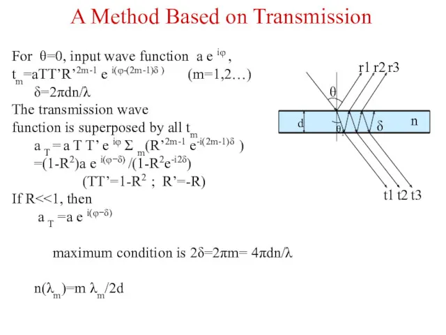
For θ=0, input wave function a e iφ ,
tm=aTT’R’2m-1 e
For θ=0, input wave function a e iφ ,
tm=aTT’R’2m-1 e
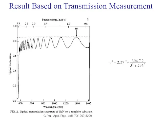
Result Based on Transmission Measurement
Result Based on Transmission Measurement
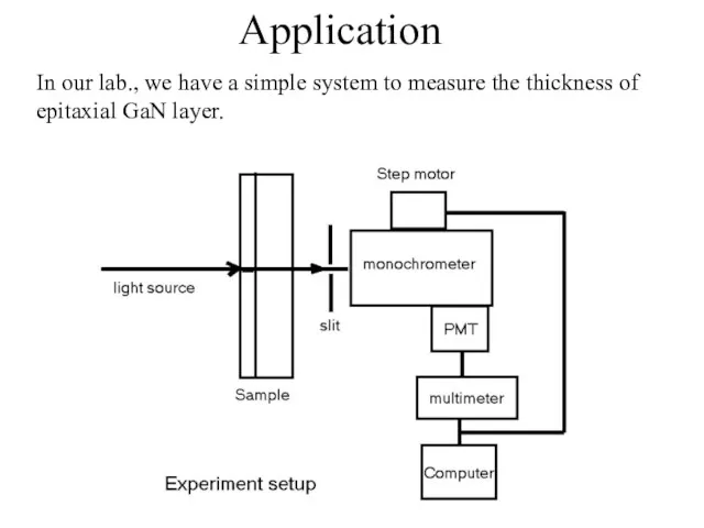
Application
In our lab., we have a simple system to measure the
Application
In our lab., we have a simple system to measure the
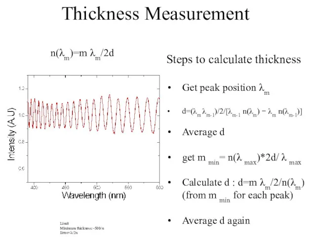
n(λm)=m λm/2d
Thickness Measurement
Steps to calculate thickness
Get peak position λm
d=(λm λm-1)/2/[λm-1 n(λm)
n(λm)=m λm/2d
Thickness Measurement
Steps to calculate thickness
Get peak position λm
d=(λm λm-1)/2/[λm-1 n(λm)
 Алгебра и геометрия. Основные понятия
 Объём цилиндра в заданиях ЕГЭ
 Десятичные дроби произвольного знака
 Урок по математике Деление круглых чисел 3 класс ОС Школа 2000...
 Функции y = tgx и y = ctgx, их свойства и графики
 Безопасность в лесу
 Тождественные преобразования логарифмических выражений
 Экологическая викторина. Жизнь в стиле ЭКО
 Арксинус, арккосинус, арктангенс и арккотангенс. Алгебра и начало анализа 10 класс
 Обобщающий урок по теме параллелограмм 8 класс
 Учимся считать и решать задачи.
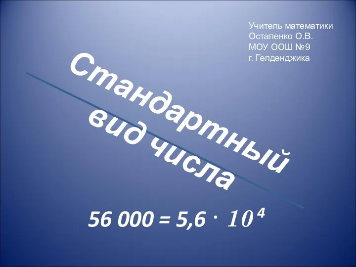 Стандартный вид числа
 Размерности. Подобие. Моделирование
 Развитие математической грамотности у школьников
 Урок по теме Число и цифра ноль.
 Векторы в пространстве. Сложение и вычитание векторов
 Приближенные значения чисел. Округление чисел
 Второй и третий признаки подобия треугольников
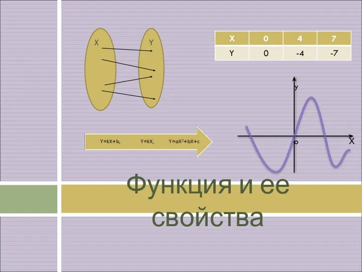 Функция и ее свойства
 Единицы измерения площади и объема
 Арифметическая и геометрическая прогрессии
 Многогранники
 Линейная алгебра и аналитическая геометрия. Дифференциальное исчисление
 Совершенствование навыка решения текстовых задач.
 Золотое сечение
 Властивості коренів. Розв′язування задач
 Приемы быстрого счета
 Соотношение между сторонами и углами прямоугольного треугольника