- Introduction of the ILS/VOR/DME

Содержание
- 2. Main ideas What is navigation? What is navigation used for? ILS ; VOR/DME
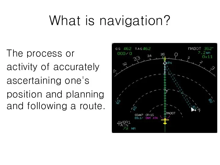
- 3. What is navigation? The process or activity of accurately ascertaining one's position and planning and following
- 4. What is navigation used for? Navigation is the art and science of determining the position of
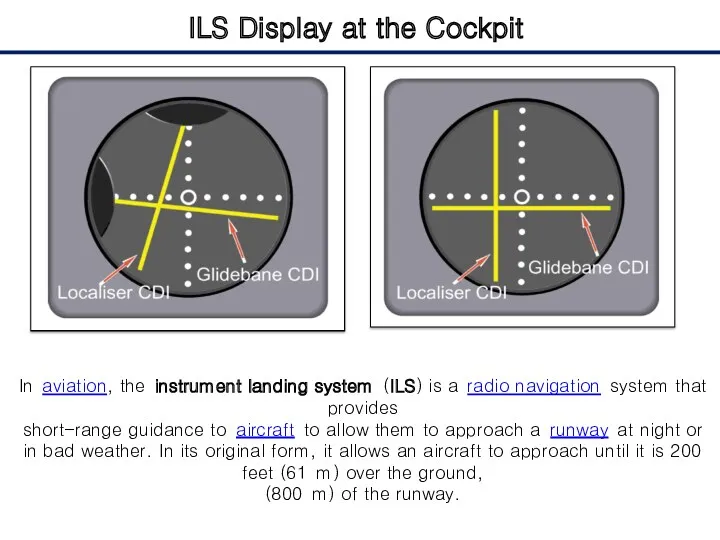
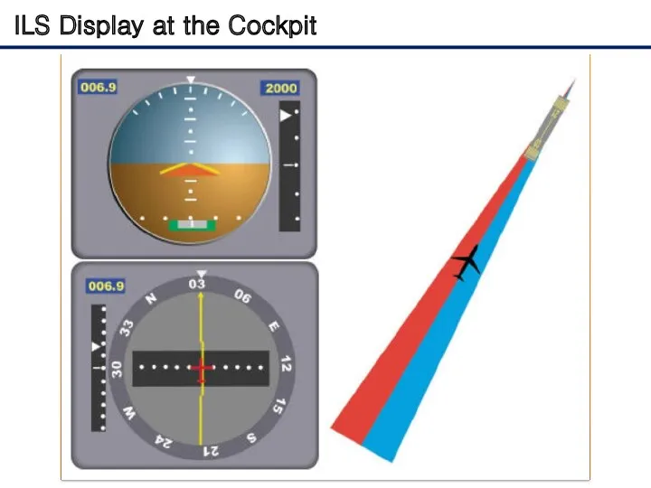
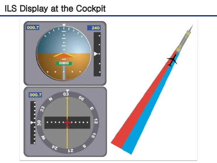
- 5. ILS Display at the Cockpit In aviation, the instrument landing system (ILS) is a radio navigation
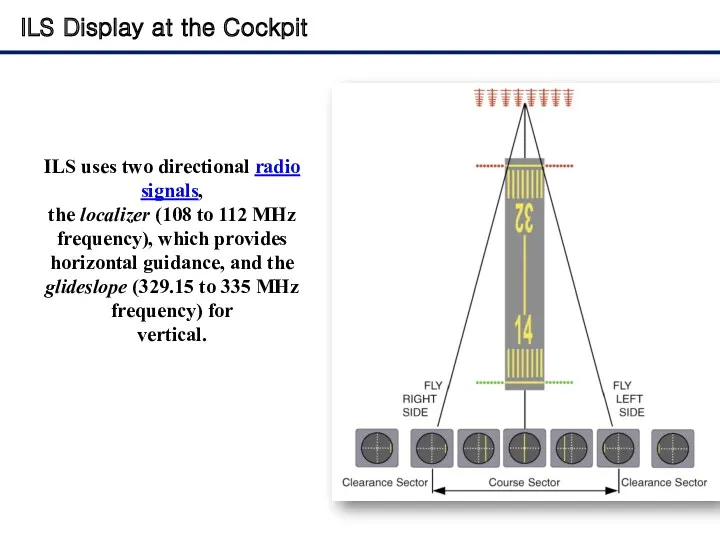
- 6. ILS Display at the Cockpit ILS uses two directional radio signals, the localizer (108 to 112
- 7. ILS Display at the Cockpit
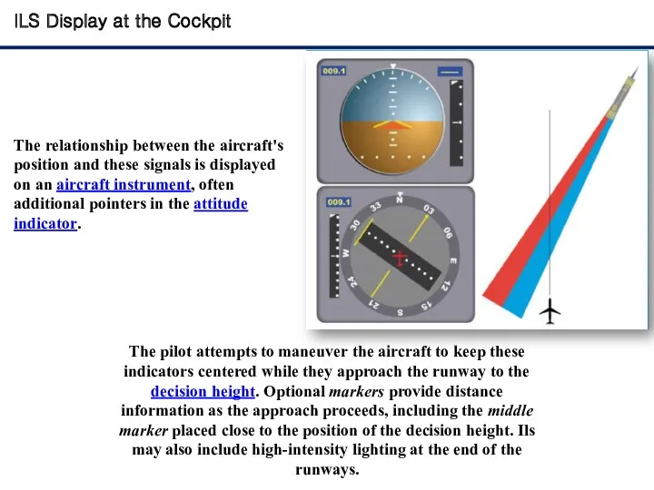
- 8. ILS Display at the Cockpit The relationship between the aircraft's position and these signals is displayed
- 9. ILS Display at the Cockpit
- 10. ILS Display at the Cockpit
- 11. ILS Display at the Cockpit
- 12. ILS Display at the Cockpit
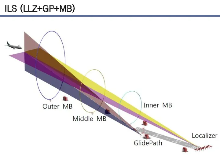
- 13. ILS (LLZ+GP+MB)
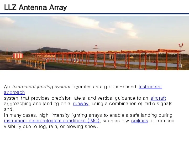
- 14. LLZ Antenna Array An instrument landing system operates as a ground-based instrument approach system that provides
- 15. GP Antenna Array
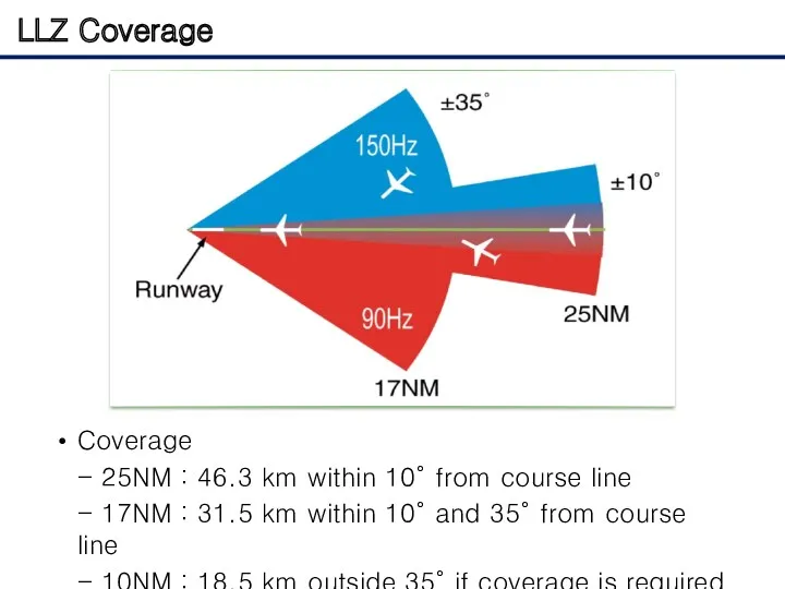
- 16. LLZ Coverage Coverage - 25NM : 46.3 km within 10° from course line - 17NM :
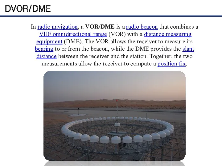
- 17. DVOR/DME In radio navigation, a VOR/DME is a radio beacon that combines a VHF omnidirectional range
- 18. VOR Display at the Cockpit
- 19. DVOR/DME The VOR system was first introduced in the 1930s, but didn't enter significant commercial use
- 20. DVOR Antenna Array
- 21. Phase Difference of each position
- 22. DME Antenna
- 24. Скачать презентацию
Main ideas
What is navigation?
What is navigation used for?
ILS ; VOR/DME
Main ideas
What is navigation?
What is navigation used for?
ILS ; VOR/DME
What is navigation?
The process or
activity of accurately
ascertaining one's
position
What is navigation?
The process or
activity of accurately
ascertaining one's
position
What is navigation used for?
Navigation is the art and science of
determining
What is navigation used for?
Navigation is the art and science of
determining
ILS Display at the Cockpit
In aviation, the instrument landing system (ILS) is a radio navigation system
ILS Display at the Cockpit
In aviation, the instrument landing system (ILS) is a radio navigation system
ILS Display at the Cockpit
ILS uses two directional radio
signals,
the localizer (108 to
ILS Display at the Cockpit
ILS uses two directional radio
signals,
the localizer (108 to
ILS Display at the Cockpit
ILS Display at the Cockpit
ILS Display at the Cockpit
The relationship between the aircraft's position and
ILS Display at the Cockpit
The relationship between the aircraft's position and
ILS Display at the Cockpit
ILS Display at the Cockpit

ILS Display at the Cockpit
ILS Display at the Cockpit
ILS Display at the Cockpit
ILS Display at the Cockpit
ILS Display at the Cockpit
ILS Display at the Cockpit
ILS (LLZ+GP+MB)
ILS (LLZ+GP+MB)
LLZ Antenna Array
An instrument landing system operates as a ground-based instrument approach
system that provides
LLZ Antenna Array
An instrument landing system operates as a ground-based instrument approach
system that provides
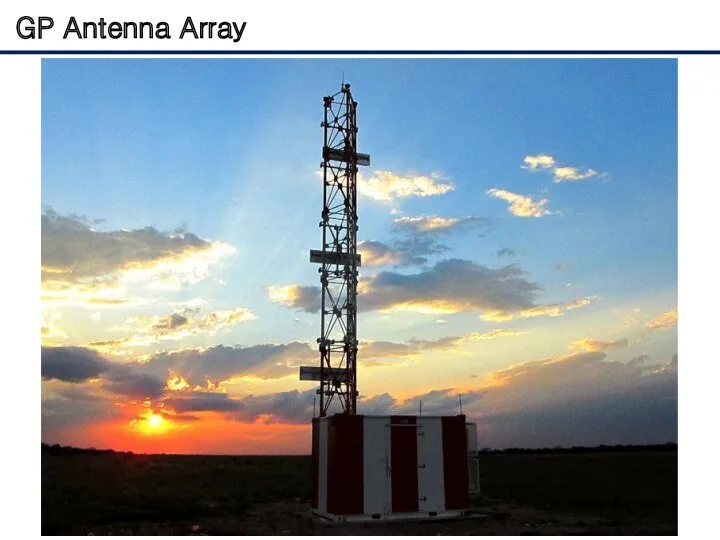
GP Antenna Array
GP Antenna Array
LLZ Coverage
Coverage
- 25NM : 46.3 km within 10° from course line
-
LLZ Coverage
Coverage
- 25NM : 46.3 km within 10° from course line
-
DVOR/DME
In radio navigation, a VOR/DME is a radio beacon that combines a
VHF omnidirectional range (VOR) with a distance
DVOR/DME
In radio navigation, a VOR/DME is a radio beacon that combines a
VHF omnidirectional range (VOR) with a distance
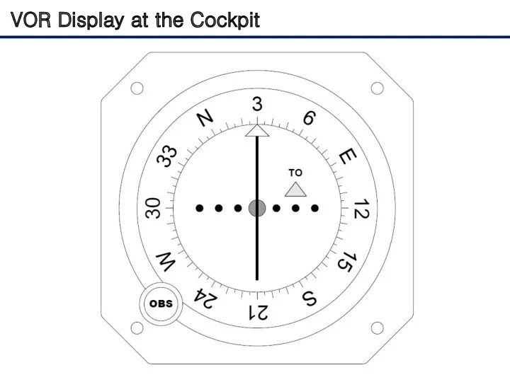
VOR Display at the Cockpit
VOR Display at the Cockpit
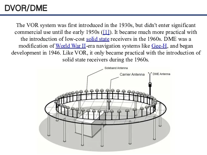
DVOR/DME
The VOR system was first introduced in the 1930s, but didn't
DVOR/DME
The VOR system was first introduced in the 1930s, but didn't
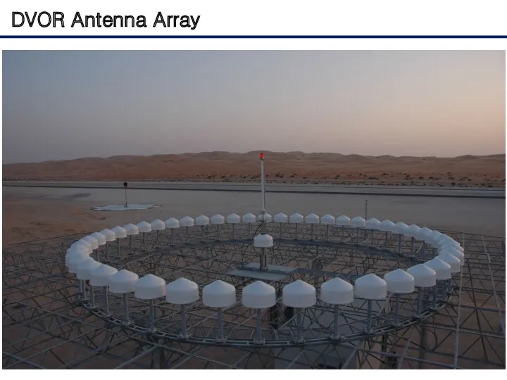
DVOR Antenna Array
DVOR Antenna Array
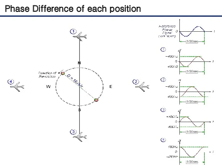
Phase Difference of each position
Phase Difference of each position
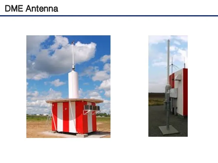
DME Antenna
DME Antenna
 Технология объектно-ориентированного проектирования ИС (разработки программного обеспечения) – Rational Unified Process (RUP)
 Объектно-ориентированное программирование. Практические работы Pascal ABC
 Программа Figma
 Руководство пользователя для онлайн-курса ГПА
 Интерактивная презентация для цикла уроков в 10 классе Создание Веб-сайта. Язык HTML. ;2.
 Экскурсия по виртуальному музею Компьютерной графики (Office 2007)
 Линии связи
 Компьютерные технологии интеллектуальной поддержки управленческих решений
 Управление ремонтами и обслуживанием оборудования. Решение на основе 1С:Предприятие 8
 Functions are objects. Main concepts behind Python functions
 Training Manual
 Стиснення та архівування даних
 Розробка клієнтського програмного забезпечення для корпоративних додатків на платформі Java
 Welcome. Anti-virus
 Системы счисления. Позиционные и непозиционные системы
 Стандартизация программного обеспечения
 Решения для электронного правительства и электронизация государственных услуг — БАРС Груп
 Моделирование и формализация
 Управление в логистических информационных системах (Информационные системы планирования и управления ресурсами предприятия)
 Работа с VirtualBox, установка рабочих станций и подготовка для включения в одноранговую сеть
 Lazarus. Порядок создания приложения
 Школьная газета АстраWork
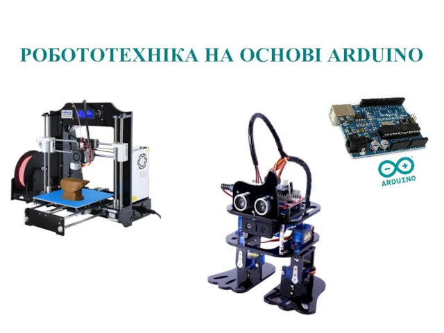 Робототехніка на основі Arduino
 Programming logic and design seventh edition. Chapter 5. Looping
 Инструкция по заполнению регистрационной формы конференции
 Метод PERT и управление проектами
 Модели данных
 Технічні і програмні засоби КС реального часу. (Тема 10)